Transcription
IEEE JOURNAL ON SELECTED AREAS IN COMMUNICATIONS, VOL. 35, NO. 11, NOVEMBER 20172479Distributed Service Function ChainingMilad Ghaznavi, Nashid Shahriar, Shahin Kamali, Reaz Ahmed, and Raouf Boutaba, Fellow, IEEEAbstract— A service-function chain, or simply a chain, is anordered sequence of service functions, e.g., firewalls and loadbalancers, composing a service. A chain deployment involvesselecting and instantiating a number of virtual network functions (VNFs), i.e., softwarized service functions, placing VNFinstances, and routing traffic through them. In the currentoptimization-models of a chain deployment, the instances ofthe same function are assumed to be identical, while typicalservice providers offer VNFs with heterogeneous throughput andresource configurations. The VNF instances of the same functionare installed in a single physical machine, which limits a chainto the throughput of a few instances that can be installed inone physical machine. Furthermore, the selection, placement, androuting problems are solved in isolation. We present distributedservice function chaining that coordinates these operations, placesVNF-instances of the same function distributedly, and selectsappropriate instances from typical VNF offerings. Such a deployment uses network resources more efficiently and decouples achain’s throughput from that of physical machines. We formulatethis deployment as a mixed integer programming (MIP) model,prove its NP-Hardness, and develop a local search heuristic calledKariz. Extensive experiments demonstrate that Kariz achieves acompetitive acceptance-ratio of 76%–100% with an extra cost ofless than 24% compared with the MIP model.Index Terms— Service function chaining, network functionvirtualization, virtual network function, placement, routing.I. I NTRODUCTIONSERVICE-FUNCTION chain, or simply a chain, is anordered sequence of service-functions composing a service [37]. For example in a typical data-center network, trafficfrom a server passes through an IDS, a firewall, and a NATbefore reaching to the Internet [5]. Until recently, functionshave been vertically integrated in dedicated hardware middleboxes, i.e., a chain of pricey middleboxes are provisionedto provide throughput for peak-load, and traffic must berouted through fixed locations in which these middleboxes areplaced [36].Network function virtualization decouples network functions from underlying hardware and implements them as software appliances on virtualized commodity hardware. Theseappliances are called Virtual Network Functions (VNFs).In this way, a chain of inexpensive VNFs provide same packetprocessing functions at a desired throughput, and we can routeAManuscript received April 1, 2017; revised September 12, 2017; acceptedSeptember 25, 2017. Date of publication October 5, 2017; date of currentversion December 1, 2017. (Corresponding author: Raouf Boutaba.)M. Ghaznavi, N. Shahriar, R. Ahmed, and R. Boutaba are withthe University of Waterloo, Waterloo, ON N2L 3G1, Canada (e-mail:eghaznav@uwaterloo.ca; nshahria@uwaterloo.ca; r5ahmed@uwaterloo.ca;rboutaba@uwaterloo.ca).S. Kamali is with the University of Manitoba, Winnipeg, MB R3T 2N2,Canada (e-mail: shahin.kamali@umanitoba.ca).Color versions of one or more of the figures in this paper are availableonline at http://ieeexplore.ieee.org.Digital Object Identifier 10.1109/JSAC.2017.2760178traffic through appropriate locations in which VNF-instancesare dynamically placed. Such a deployment reduces capitaland operational costs and optimizes network operations.A chain deployment involves selecting and instantiating anumber of VNFs, placing these VNF-instances, and routingtraffic through them. An optimal chain deployment coordinatesthe selection, placement, and routing to minimize resourcesallocated while satisfies the resource capacity and location constraints. Existing VNF chaining models have severallimitations as follows.A. Gaps in SelectionMost of the optimization models [8], [10], [45] do notconsider the typical VNF offerings and assume that VNFs ofa same function are identical in their resource consumptionand throughput. Service providers offer VNFs with different configurations to provide predictable quality of service.For example, HP offers virtual IPSec [3] that providesthroughputs of 268, 580, and 926 Mbps assuming respectively 1, 4, and 8 CPU cores. Similarly, Riverbed offersWAN-optimizers [6] with throughputs of 10 and 50 Mbpsgiven respectively 2 and 4 CPU cores. Note that the correlationbetween the throughput and resource consumption is notnecessarily linear. In practice, predicting the performance ofservice-functions is not trivial [9], [13], [25].B. Gaps in Placement and RoutingTo process a traffic flow, some models use a single physicalmachine to place VNFs of a same function [8], [10], [27],[29], [32] or even all VNFs of a chain [39]. However, doingso severely limits throughput of the function and chain toa few VNFs that can be instantiated in a physical-machine.The throughput of these instances might not be sufficient toprocess the total traffic routed through them, and this problemis exacerbated by the fact that traffic volume through functionshas an increasing trend [23], [47].C. Gaps in CoordinationA VNF cannot be selected if there is not sufficient resourcesto place its instances. Further, it is impractical to placean instance in a given location when adequate bandwidthis not available to route traffic from/to the location. Toachieve an optimal deployment of service chains, selection,placement, and routing must be performed in a coordinatedmanner; otherwise, the deployment results in sub-optimalutilization of network resources and quality of service. Mostof existing solutions solve the placement and routing in isolation [15], [17], [36], [46]. There are few solutions [10], [32]0733-8716 2017 IEEE. Personal use is permitted, but republication/redistribution requires IEEE permission.See http://www.ieee.org/publications standards/publications/rights/index.html for more information.
2480IEEE JOURNAL ON SELECTED AREAS IN COMMUNICATIONS, VOL. 35, NO. 11, NOVEMBER 2017that coordinate the placement and routing; however, they treatthe selection of VNFs separately.To fill the above gaps, we present distributed servicefunction chaining (DSFC). For each function of a chain,DSFC selects from provided VNF offerings and determinesthe appropriate number of VNF-instances to be placed. DSFCplaces these instances in a way that VNFs of a same functioncan be installed distributedly in multiple machines. Sucha placement decouples a chain’s throughput from physicalmachines. Further, DSFC, utilizing the global knowledge ofthe network, routes traffic and distributes the load among theVNF-instances. DSFC coordinates selection, placement, androuting operations in such a way that network resources areutilized more efficiently.Specifically, our contributions in this paper are: i) we modeland solve DSFC using mixed integer programming (MIP), andprove its NP-Hardness. ii) for larger networks, we proposeKariz, a local search heuristic that employs a tuning parameter to balance the speed-accuracy trade-off; iii) we performextensive simulations to evaluate Kariz against the MIP implementation for various chain-lengths and throughput-demands.The results demonstrate that Kariz achieves the competitiveacceptance ratio of 76-100% at an extra cost of less than 24%,in comparison to the MIP implementation.The rest of the paper is organized as follows. In § II,we study related works. § III discusses the system implementation and deployment challenges. We present our problemformulation in § IV. Our solution is proposed and evaluatedin § V and § VI, respectively. Lastly, § VII concludes thispaper.II. R ELATED W ORKA. SelectionVNF-P [32] studies a hybrid deployment scenario usinghardware-middleboxes and VNFs to provide a requested service. VNF-OP [10], [22], JoraNFV [44], and [29] model batchdeployments of multiple chains. Reference [34] is a schedulingframework for deploying VNFs. These papers assume thatVNFs of the same function are identical. Slick [8] is aframework that allows users to write fine-grained elements toperform custom packet-processing. Predicting the performanceof such arbitrary packet-processing element is not trivial.In contrast to these studies, we select appropriate VNFs fromdifferent typical offerings providing predictable performance.B. PlacementSplit/Merge [38] and OpenNF [18] redistribute packetprocessing across a collection of VNF-instances. In contrast toDSFC, they do not focus on placement optimization models.Stratos [17] orchestrates VNF-instances on a remote cloud.It uses a rather simple technique that places VNFs of a chainas closely as possible to each other. JVP [27] considers therelation of bandwidth usage and host resource usage in thedeployment of chains. However, JVP instantiates a singleVM for each VNF. VNF-OP [10] and VNF-P [32] place allVNF-instances of a function on a single machine. In contrastto these works, we place multiple VNF-instances of eachfunction distributedly. CoMb [39] is an architecture designedto consolidate the chain deployment. In contrast to DSFC,CoMb places all VNFs of a chain that deal with the samesession at a fixed location. [30] only optimize the placementof VNFs and does not consider the routing.C. RoutingUnlike our work, [15], [36], [46] optimize only bandwidth usage. In processing a network flow, Slick [8] usesa single instance for each function. On the contrary, DSFCroutes traffic among multiple VNF-instances for each function.Stratos [17] solves the routing separately after placing VNFinstances. LightChain [22] optimizes the number of switchesbetween ingress and egress points of chains. The authorsof [19] solve the joint placement and routing problem using adynamic programming algorithm. E2 [34] instantiates VNFsin certain servers to optimize the inter-server communication.Although [10], [19], [32], [34] coordinate the placement androuting, they still treat the selection separately. We jointlyoptimize routing, placement, and selection that was not thefocus of these studies.III. C HALLENGESA chain specifies that the traffic originating from a source,is processed by an ordered sequence of functions, and finallyis delivered to a target. To deploy a chain distributedly, severalsystem and optimization challenges have to be addressed.A. System Implementation ChallengesService-functions often operate on data-packets at a flowgranularity and maintain state information on the flows andsessions they process [41], [43]. State information consistsof configuration and statistical data, and differs from onefunction to another. If a function is replaced with multipleVNF-instances, the functionality should not change, and theseinstances must act in concert. Further, the traffic processedby a single function, should now be processed by multipleVNF-instances. Thus, consistent state distribution and consistent traffic distribution among the VNF-instances are essential.1) Consistent State Distribution: Deployment of multipleVNF-instances to provide a function requires distribution ofthe state information. Hence, we need to model the state information and distribute it among the VNF-instances consistently.The state information can be classified as internal or external. The internal state is stored and used only by a singleinstance, while the external state is distributed and sharedacross multiple instances. Since the state information is storedin a key-value store [24], [41], data structures like distributed hash-tables and technologies like remote direct memoryaccess (RDMA) can fulfill this challenge efficiently. Moreover,it might be required to modify the functions to cope with thedefined model. There are abstraction models and system implementations that address this challenge. Rajagopalan et al. [38]introduce a system-level abstraction called Split/Merge thatstores the internal state exclusively inside each VNF-instance,while the external state is distributed and accessible by otherinstances. As a proof of concept, they implemented FreeFlow
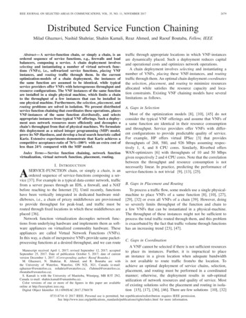
GHAZNAVI et al.: DISTRIBUTED SERVICE FUNCTION CHAININGFig. 1.2481Distributed deployment of a chain.as a Split/Merge system, and ported Bro IDS [35] inside it.Further, they analyzed and confirmed the compatability of twoother functions, i.e. application delivery controller and statefulNAT64. In addition, Joseph and Stoica [24] provide a modelto describe different functions. As concrete examples, firewall,NAT and layer4 and layer 7 load-balancer are describedusing the proposed model. Further, Gember et al. [16] andOpenNF [18] introduce a unified framework to manage stateinformation.2) Consistent Traffic Distribution: Replacing a single function with multiple VNF-instances requires splitting and distributing the traffic load among these instances. Per-flow trafficsplitting distributes the traffic in the granularity of flows, andpackets of a flow have to be routed along the same path.Split/Merge [38] utilizes a similar approach. However, thisapproach does not support accurate load-distribution and isnot always applicable. For instance, if the load of a flow ishigher than the throughput of an assigned VNF-instance, thatinstance cannot handle the load and we have to split the trafficinto a smaller granularity. Flowlet switching [7], [40] can beleveraged to split the traffic into a finer granularity. A flowletis a “burst of packets from the same flow followed by an idleinterval” [40]. If the interval between two flowlets is greaterthan the maximum delay difference between parallel paths,the second flowlet—and consequently following flowlets—can be sent through different paths. Thus, a single flowcan be split into multiple paths without packet-reordering.Furthermore, accurate load balancing is achieved using shortflowlet intervals ([50, 100]ms) [40]. Specifically, flowlets areabundant in data-center networks since the latency is very lowand the traffic is intensively bursty [26]. In addition to thesedistributed methods, the central schemes leveraging SDN andOpenFlow capabilities [28] can also be used. For instance,group tables [4] can be used to split and balance the traffic.We have shown the feasibility of distributed deployment ofVNF-instances to provide a function and distributing trafficamong these instances. Next, we state the assumptions thatground our optimization model: The state information of a function can be consistentlydistributed among multiple VNF-instances. This assumption holds for the state information of a single flow. The traffic can be consistently distributed into multiplepaths among multiple VNF-instances. This assumptionholds for a single flow.B. Optimization ChallengesThe optimization challenge is in computing an optimalallocation of host and bandwidth resources to a chain.TABLE IVNF SEach function in a chain is replaced with a number ofVNF-instances providing the requested throughput. Theseinstances are placed in a set of chosen hosts. In addition,the traffic is split and routed among the instances. Thus, certaindecisions have to be made optimally: number of VNF-instances(selection), placement of these instances, and routing thetraffic through the placed instances. These decisions are interdependent and must be made in a coordinated manner.Fig. 1 shows a chain deployment. The network of Fig. 1aincludes 6 hosts, each with an 8-core CPU and 64 GBresidual memory. For simplicity, switches are not shown, andthe presented paths are disjoint in this example. All pathshave 130 Mbps available bandwidth. The chain of Fig. 1bincludes 2 functions with 210 Mbps throughput: an IDS anda firewall (FW). The flow comes from the host A, the source,is processed by IDS and FW, and then sent to host F,the target. As listed in Table I, there are 4 VNF types for IDSand FW. Fig. 1c depicts the chain deployed in the network, andFig. 1d shows the logical representation of this deployment:with 3 instances for IDS (1 IDS1 2 IDS2 ) and 2 instancesfor FW (1 FW1 1 FW2 ). The IDS instances are installedin hosts B and D. The flow splits, and 80 Mbps and 130 Mbpsare routed from the source to hosts B and D, respectively. FWinstances are installed in hosts B and E. In host B, the flowafter being processed by IDS2 is sent to FW1 . IDS1 and IDS2forward the flow to host C in which instance FW2 is placed.Finally, the flow from the FW instances is sent to the target.Note that it is possible to place the VNF-instances in the sourceand target if sufficient host resources are available.IV. D ISTRIBUTED S ERVICE F UNCTION C HAININGWith the assumptions and challenges established, we nowintroduce the formal definitions and the mathematical model.Table II lists important notations used in this paper.A. Definitions1) Physical Resources: R {CPU, memory, storage, }represents a set of available physical resources.2) Network: Graph G (N, E) is the substrate network, where N and E are substrate nodes and links, respectively. cmr R is the residual capacity of node m for
2482IEEE JOURNAL ON SELECTED AREAS IN COMMUNICATIONS, VOL. 35, NO. 11, NOVEMBER 2017TABLE IIN OTATION bandwidth of links to traffic type u, and X u N /{t } X u .If Yu {ymu : m N, u Vu } identifies the VNFinstantiated for function u, let Y u N Yu . Finally, Z u {z mu : m N} denotes the allocated throughput of type u inevery node, and Z u N Z u .1) Node Capacity Constraint: Eq. 1 ensures that instancesare placed with respect to the substrate nodes capacities. ymu dur cmr(1) m N : r R :u V2) Location Constraint: Equalities in Eq. 2 ensure that aninstance of u s and an instance of u t are placed only in s Nand t N, respectively. ymu s 0ysu s 1,m N/{s} yt u t 1,ymu t 0(2)m N/{t }3) Substrate Link Capacity Constraint: Eq. 3 makes surethat the capacities of substrate links are not violated. uu mn E, m n :(x mn x nm) cmn(3)resource r R. Set E m denotes incident links on node m.Moreover, mn E is the link between node m N and noden N and has a residual bandwidth capacity of cmn R .3) Chain: Symbols with over-line are for chain definitions.Forwarding graph G (N , A) denotes a chain. N includesfunctions V N , and two endpoints s and t. Traffic flowcoming from s N is processed by functions in the chain,and is forwarded to t N . Respectively, s and t are thesource and target of the traffic. The corresponding substratenodes for source and target are respectively s N and t N.Function v f (u) follows function u. We define ring uv Aas 2 consecutive functions u and v, where v f (u).We assume that u generates traffic type u and v consumesthis traffic type. Each ring uv has the throughput demand bdenoting integer traffic volume flow generated or consumedby the ring nodes.4) VNFs: Set V denotes VNFs. A VNF u V hasthroughput qu R showing the maximum traffic that ucan process. dur R is the demand of u for resource r .These demands include the overhead of accessing distributedstate information. For s and t, we assume that there are VNFsu s and u t , respectively. These VNFs have throughput b andno demand for any resource. Finally, VNFs of type u areidentified by Vu .B. Mathematical Modelu R is the traffic volume of type u N /{t} onVariable x mnsubstrate link mn. Target t is excluded since it only consumestraffic; thus, no traffic of this type exists in the network. Variable ymu Z is the number of instances of VNF u in substratenode m. VNF instances of Vu installed in node m providethroughput of type u. Variable z mu R denotes the allocatedthroughput of these VNF instances. A solution for the problemis shown by a tuple of allocation vectors (X, Y, Z ), definedu : mn E} be allocatedas follows. Let vector X u {x mnu N4) Throughput Constraint: Eq. 4 ensures that the aggregatethroughput capacity of instances of type u placed in substratenode m is more than allocated throughput z mu . ymu qu z
tively 1, 4, and 8 CPU cores. Similarly, Riverbed offers WAN-optimizers [6] with throughputs of 10 and 50 Mbps given respectively 2 and 4 CPU cores. Note that the correlation between the throughput and resource consumption is not necessarily linear. In practice, predicting the perform