Transcription
INSTRUCTION MANUALE L E C T R I CL E V E LC O N T R O L SLINC L471 L471SC LV471 L971SERIESRecognized as aworld-class leader inElectric & Pneumaticlevel control switches,flow indicators,chemical meteringpumps, andallied products.
INSTRUCTION MANUALO R D E R I N GI N F O R M A T I O NTo Order, Call 800.455.LINCOr FAX your order anytime to215.293.0498For the Nearest AuthorizedRepresentative:By Telephone: 800.455.LINC forthe US & Canada, 215.293.0465or 215.441.0800 for InternationalcustomersBy Fax: 215.293.0498E-mail:info@miltonroy.comTechnical SupportBy Telephone: 800.455.LINCBy e-mail:info@miltonroy.comPage 1L I N C M I LT O N R OY 2 0 1 I V Y L A N D R O A D I V Y L A N D PA , 1 8 9 7 4 U S A T E L . 2 1 5 . 2 9 3 . 0 4 6 5 FA X 2 1 5 . 2 9 3 . 0 4 9 8
INSTRUCTION MANUALTABLEOFCONTENTSContents –L471, 471SC, LV471, L971 Electric Level Controls . . . . . . . . . . . . . . . . . . . . . . . . . . PageL471 & L471SC Series Ordering Chart . . . . . . . . . . . . . . . . . . . . . . . . . . . . . . . . . . . . . . . . . . . . . . . 3-4Scope Of This Manual . . . . . . . . . . . . . . . . . . . . . . . . . . . . . . . . . . . . . . . . . . . . . . . . . . . . . . . . . . . . . 5Product Description . . . . . . . . . . . . . . . . . . . . . . . . . . . . . . . . . . . . . . . . . . . . . . . . . . . . . . . . . . . . . . . 5Operation . . . . . . . . . . . . . . . . . . . . . . . . . . . . . . . . . . . . . . . . . . . . . . . . . . . . . . . . . . . . . . . . . . . . . . . 5Features . . . . . . . . . . . . . . . . . . . . . . . . . . . . . . . . . . . . . . . . . . . . . . . . . . . . . . . . . . . . . . . . . . . . . . . . 5Installation . . . . . . . . . . . . . . . . . . . . . . . . . . . . . . . . . . . . . . . . . . . . . . . . . . . . . . . . . . . . . . . . . . . . . . 6Maintenance . . . . . . . . . . . . . . . . . . . . . . . . . . . . . . . . . . . . . . . . . . . . . . . . . . . . . . . . . . . . . . . . . . . . . 7Float and Arm. . . . . . . . . . . . . . . . . . . . . . . . . . . . . . . . . . . . . . . . . . . . . . . . . . . . . . . . . . . . . . . . . . . . 7Relay . . . . . . . . . . . . . . . . . . . . . . . . . . . . . . . . . . . . . . . . . . . . . . . . . . . . . . . . . . . . . . . . . . . . . . . . . . 7Switch . . . . . . . . . . . . . . . . . . . . . . . . . . . . . . . . . . . . . . . . . . . . . . . . . . . . . . . . . . . . . . . . . . . . . . . . . . 7Electric Relays: Installation and Maintenance . . . . . . . . . . . . . . . . . . . . . . . . . . . . . . . . . . . . . . . . . . 13Assembly Drawings & Parts ListsFigure 1, L471-01, 21 Level Switch . . . . . . . . . . . . . . . . . . . . . . . . . . . . . . . . . . . . . . . . . . . . . . . . . . . 8L471-01, 21 Level Switch Parts List. . . . . . . . . . . . . . . . . . . . . . . . . . . . . . . . . . . . . . . . . . . . . . . . . . . 8Figure 2, L471-02, 03 Level Switch . . . . . . . . . . . . . . . . . . . . . . . . . . . . . . . . . . . . . . . . . . . . . . . . . . . 9L471-02, 03 Level Switch Parts List. . . . . . . . . . . . . . . . . . . . . . . . . . . . . . . . . . . . . . . . . . . . . . . . . . . 9Figure 3, L471-01-04 Level Switch. . . . . . . . . . . . . . . . . . . . . . . . . . . . . . . . . . . . . . . . . . . . . . . . . . . 10L471-01-04 Level Switch Parts List . . . . . . . . . . . . . . . . . . . . . . . . . . . . . . . . . . . . . . . . . . . . . . . . . . 10Figure 4, L471-39, 79 Level Switch . . . . . . . . . . . . . . . . . . . . . . . . . . . . . . . . . . . . . . . . . . . . . . . . . . 11L471-39, 79 Level Switch Parts List. . . . . . . . . . . . . . . . . . . . . . . . . . . . . . . . . . . . . . . . . . . . . . . . . . 11Figure 5, L471-69, 89 Level Switch . . . . . . . . . . . . . . . . . . . . . . . . . . . . . . . . . . . . . . . . . . . . . . . . . . 12L471-69, 89 Level Switch Parts List. . . . . . . . . . . . . . . . . . . . . . . . . . . . . . . . . . . . . . . . . . . . . . . . . . 12Figure 6, Electric Relay 21593 . . . . . . . . . . . . . . . . . . . . . . . . . . . . . . . . . . . . . . . . . . . . . . . . . . . . . . 14Electric Relay 21593 Parts List . . . . . . . . . . . . . . . . . . . . . . . . . . . . . . . . . . . . . . . . . . . . . . . . . . . . . 14Figure 7, L471SC-01, 02 Level Switch. . . . . . . . . . . . . . . . . . . . . . . . . . . . . . . . . . . . . . . . . . . . . . . . 15L471SC-01, 02 Level Switch Parts List . . . . . . . . . . . . . . . . . . . . . . . . . . . . . . . . . . . . . . . . . . . . . . . 15Figure 8, L471SC-03, 04 Level Switch. . . . . . . . . . . . . . . . . . . . . . . . . . . . . . . . . . . . . . . . . . . . . . . . 16L471SC-03, 04 Level Switch Parts List . . . . . . . . . . . . . . . . . . . . . . . . . . . . . . . . . . . . . . . . . . . . . . . 16LV471 & L971 Series Ordering Chart . . . . . . . . . . . . . . . . . . . . . . . . . . . . . . . . . . . . . . . . . . . . . . . . 17Figure 9, LV471-04, LV471-04-04 Level Switch . . . . . . . . . . . . . . . . . . . . . . . . . . . . . . . . . . . . . . . . . 18LV471-04, LV471-04-04 Level Switch Parts List . . . . . . . . . . . . . . . . . . . . . . . . . . . . . . . . . . . . . . . . 19Figure 10, L971-01, L971-01-04 Level Switch . . . . . . . . . . . . . . . . . . . . . . . . . . . . . . . . . . . . . . . . . 20L971-01, L971-01-04 Level Switch Parts List . . . . . . . . . . . . . . . . . . . . . . . . . . . . . . . . . . . . . . . . . . 21L I N C M I LT O N R O Y 2 0 1 I V Y L A N D R O A D I V Y L A N D PA , 1 8 9 7 4 U S A T E L . 2 1 5 . 2 9 3 . 0 4 6 5 F A X 2 1 5 . 2 9 3 . 0 4 9 8Page 2
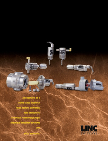
LEVELCONTROLSWITCHESL I N C - L 4 7 1 & L 4 7 1 S C S E R I E SThe LINC-L471 & L471SC Series:Electric Level Control SwitchesApplication:Used as a high & low level control,the L471 & L471SC can activatealarms, provide a switch input forcontrol systems, or perform a varietyof desired electrical switch operationsactuated by a liquid or liquid interface.Operation:As the float is moved by varying liquid height, a magnet is moved closerto or further away from a switch enclosure. As the magnet moves closer, areed switch in the enclosure closes.As the magnet moves further away, theswitch opens. The arm containing themagnet also acts as a counterweightfor the float.The float is small and will operate inliquids with a specific gravity as low as0.4. The interface type will operate witha specific gravity differential as low as0.1. This small float permits an economical installation in locations whereother controls would be cost prohibitive. Available with a relay mounted inan explosion-proof case allowing thecontrol of larger electrical loads. Themanual override option allows theoperator to manually move the floatarm to the test switch position.1Page 3Benefits:Features: Easy to Repair. Repairs on-site in 20 minutes with theQuick-Change switch cartridge Easy to Field Test. The Manual Override option enablesmechanical and electrical function testing while installed No Leaks. Environmentally-isolated design keepsoperational fluids away from electricalcircuitry Lower Operating Costs. Quick-Change, inexpensive replacement parts Lower Inventory. One L471 inverts for both High & Lowlevel applications Versatile. One L471 provides both normally open,and normally closed switching by simplyinverting the L471 Safe. Certified as explosion-proof 1 for Hazardous Locations: Class I, Div. 1, Groups A,B, C, D; Class II, Div. 1, Groups E, F, G;and Class III, Div.1, by CSA a Nationallyrecognized Testing Laboratory in the U.S.and Canada Corrosion Resistant. Standard 316 Stainless Steel wetted andhousing components for corrosionresistance Reliable. Sealed switch cartridge preventsdust, fluids, and corrosion frominterfering with electrical circuity High & Low PressureApplications. Available with Stainless Steel andPolypropylene displacer options forvarious process pressuresWhen a relay assembly is used, Class , Div. 1, is limited to Groups C and D.L I N C M I LT O N R OY 2 0 1 I V Y L A N D R O A D I V Y L A N D PA , 1 8 9 7 4 U S A T E L . 2 1 5 . 2 9 3 . 0 4 6 5 FA X 2 1 5 . 2 9 3 . 0 4 9 8
LEVELCONTROLSWITCHESL I N C - L 4 7 1 & L 4 7 1 S C S E R I E SSpecifications: L471 & L471SC Series Electric Level Control SwitchesPressure:1,500 psi standard, available to 5,000 psi, (1,500 psi maximum with the Manual Override option)Temperature:Specific Gravity:40 F to 400 F standard.0.4 minimum standard; interface 0.1 differential minimumMaterials:Switch Rating:316 stainless steel wetted parts are standard.SPST (SPDT optional) 100 V.A. AC, 100W DC, 3 amp inrush capability, maximum of 250 Volts, Hermetically sealedConnections:Electrical:112" conduit standard, with other sizes optionalProcess:CSA Certification:1 112" NPT standard, available in 2" NPT, 3" flanged or larger, and externally cagedListed as explosion proof for Class I, Div. 1, Groups A, B, C, D; Class II, Div. 1, Groups E, F, G; and Class III, Div. 1Ordering Chart:Series:L471L471SCBody Style:01243678Type:12Electric level controlExternally caged electric level control. Note:The body style is always "0" due to ring bolt.1,500 psi WP standard; 3,000 psi WP available 2Standard, 1 112" NPT (ring bolt on L471SC)Standard, 2" NPTStandard, 1 112" NPT, manual override 3Standard, 2" NPT, manual override 3Extd. body 4, 2" NPT, vertical displacerExtd. body 4, 2" NPT, vertical displacer, manualoverrideExtd. body 4, 2" NPT, horizontal displacerExtd. body 4, 2" NPT, horizontal displacer,manual overrideStandardHigh pressure, 5,000 psi polypropylenedisplacer, temp. 180 F max, spec. grav. 0.6 min.CSA rated to 1500 psi per single seal rating(consult factory for higher ratings)349Other 5:0203 -NInterface, 5,000 psi polypropylene displacer,temp. 180 F max, upper fluid less than: .870spec. grav; lower fluid more than: .970 spec. grav.Other gravities for interface, specify gravitiesof fluids (upper & lower)Displacer, 5,000 psi polypropylene displacer,temp. 180 F max, spec. grav. 0.5 min.Annulus plugRelay assembly 1, general purpose plugin, 24VDC DPDT 10 Amp04 -NRelay assembly 1, general purpose plugin, 120VAC DPDT 10 Amp08 -NRelay assembly 1, hermetically sealed plugin, 24VDC DPDT 10 Amp09 -NRelay assembly 1, hermetically sealed plugin, 120VAC DPDT 10 Amp05This number means special; specify yourrequirements. i.e. 3" flanged 150# RFOption Number:( )Factory will assign an option number based onspecified requirements.When a relay assembly is used, Class I, Div. 1, is limited to Groups C, and D.L471SC pressure limitation is 3,000 psi on cage.Not available on L471SC. 1500 psi maximum. Manual override.4Body style 3, 6, 7, 8 available only Type 9.5/f no further requirements are desired, omit "Other" option codes from the partnumber.123(LINCExamole: LINC-L471-21-05 electric level controlSpecify: 3" 150# RF, CS flange, 120 VAC relayL I N C M I LTLT O N R O Y 2 0 1 I V Y L A N D R O A D I V Y L A N D PA , 1 8 9 7 4 U S A T E L . 2 1 5 . 2 9 3 . 0 4 6 5 F A X 2 1 5 . 2 9 3 . 0 4 9 8Page 4
INSTRUCTION MANUALPRODUCTDESCRIPTIONScope Of This Manual:This manual describes and pro vides instructions and parts listsfor the LINC-L471, LINC L471SC, LINC-LV471 andLINC-L971 Series Electric LevelControls.Product Description:Used as a high & low levelcontrol, the L471 & L471SC canactivate alarms, provide a switchinput for control systems, or per form a variety of desired electri cal switch operations actuatedby a liquid or liquid interface.Operation:As the float is moved by vary ing liquid height, a magnet ismoved closer to or further awayfrom a switch enclosure. As themagnet moves closer, a reedswitch in the enclosure closes.As the magnet moves furtheraway, the switch opens. The armcontaining the magnet also actsas a counterweight for the float.The float is small and will oper ate in liquids with a specificgravity as low as 0.4. The inter face type float will operate witha specific gravity differential aslow as 0.1. The small float per mits an economical installationin locations where other controlswould be cost prohibitive. Withthe optional relay mounted in anexplosion-proof case, the controlof larger electrical loads can beobtained. The manual overrideoption allows the operator tomanually move the float arm tothe test switch position.The SC Series is designed toeliminate the threaded controlconnection in mounting with theuse of a bolted ring per API rec ommended practice FIND. Theexternal cage allows for installa tion of the control at any elevation.Page 5Features: All wetted parts isolated from the environment. These levelcontrols are safe even in the event of fire. *Certified as explosion proof for Hazardous Locations: Class I,Div. 1, Groups A, B, C, D; Class II, Div. 1, Groups E, F, G; & ClassIII, Div. 1. All 316 stainless steel wetted parts provide corrosion resistance. Our sealed switch assembly prevents dust, dirt, or moisture fromaffecting the level control's operation. Classified "Factory Sealed"by CSA/NRTL/C. Cartridge switch assembly provides easy field replacement andservicing. High or low alarm, normally open or normally closed operationsimply by inverting the level control.*When a relay assembly is used, Class I, Div. 1, is limited to groups C and D.L I N C M I LT O N R OY 2 0 1 I V Y L A N D R O A D I V Y L A N D PA , 1 8 9 7 4 U S A T E L . 2 1 5 . 2 9 3 . 0 4 6 5 FA X 2 1 5 . 2 9 3 . 0 4 9 8
INSTRUCTION MANUALINSTALLATIONInstallation:Before installing the level con trol, inspect the unit for anydamage. The float arm mustpivot freely. Thread the levelcontrol into the desired connec tion. See Drawing 3 forSuggested installations. Thefloat requires a minimum clear ance of 1 1/4" from the centerline of the unit for proper opera tion. For fail-safe operation as ahigh level alarm, the conduitconnection must be positionedto the highest possible location.For operation as a low levelalarm, the conduit connectionmust be positioned to the lowestpossible location. Wiring con nections may now be made. Donot allow the wiring connectionsto pull on the switch assembly.Caution: Do not exceed switchratings.LINC-L471, LINC-L471SC:SPST, 100 VA AC with 3 AMPinrush capability, maximum 250volts.Breakdown voltage is 300volts. Electrical ratings aregiven for resistive loads. Forinductive loads, de-rate theswitch rating by 50% and do notexceed the VA ratings on theinrush current. If the appliedload is inductive, such as a relayor coil, then a protective deviceshould be used to prevent"inductive kick," which may burnthe switch contacts. The protec tive device recommended isdependent on the voltage used.For DC operation, a diode simi lar to an IN34A should be wiredin parallel with the switch. SeePage 11 wiring schematic. ForAC operation, a Varistor shouldbe wired in parallel with theswitch.For SPST Switch CartridgeWiring:White - CommonBlack - Normally OpenFor SPDT Switch CartridgeWiring:White - CommonBlack - Normally ClosedRed - Normally OpenL I N C M I LT O N R O Y 2 0 1 I V Y L A N D R O A D I V Y L A N D PA , 1 8 9 7 4 U S A T E L . 2 1 5 . 2 9 3 . 0 4 6 5 F A X 2 1 5 . 2 9 3 . 0 4 9 8Page 6
INSTRUCTION MANUALMAINMaintenance:The LINC-L471 and LINC L471SC Series electric levelcontrols have been designed tobe as maintenance free as pos sible. However, the componentparts are subject to normal wearand must be inspected andreplaced as necessary.Inspection and maintenance fre quency depend upon the severi ty of service conditions.Instructions are provided in thissection for maintaining the con trols as units, i.e., float and floatarm, relay and switch cartridge.All the maintenance proceduresbelow assume that the controlhas been removed from service.The switch and relay can beserviced with the controlinstalled. The power must bedisconnected before removingthe relay enclosure cover oropening the conduit fitting.Float and ArmCheck the physical clearancefor float operation. The floatmust swing freely. Solvent clean ing of the float arm chambermay be required if used in vis cous or dirty liquids. If the floathas collapsed or is perforated,unscrew the float from the floatarm and replace with a newfloat. Use Loctite to secure thefloat to the float arm. To removethe float arm, drive out the pivotpin using a 1/8" punch. Wheninstalling the float arm, makecertain that the threaded offsetof the float arm is against thethick wall of the body.TENANCEconnected across the commonand normally closed contacts.Interrupt the coil power supplyseveral times while observingthe ohmmeter. No movementindicates a defective relay, coilor contacts. This procedureshould be repeated for each setof contacts in service.To remove a defective relay, simplypull the relay from the socket andreplace with a new relay.When ordering a replacementrelay, be certain to specify coilvoltage. After installing a newrelay, reconnect the switchleads.Switch:To test for switch malfunction,connect an ohmmeter acrossthe electrical leads and observethe meter as the float assemblyis mechanically operated. Nometer movement indicates aswitch failure.To replace a switch on theLINC-L471 or LINC-L471SCSeries, pull out the switch car tridge along with the grommetthrough the conduit adapter.Slide the new switch cartridgeinto the body. Route the switchwired through the grommet andseat the grommet in the conduitadapter.Relay:To test for proper relay function,disconnect the switch leads fromthe relay socket. Apply appro priate voltage to the coil termi nals and observe the relay con tact closure with an ohmmeterPage 7L I N C M I LT O N R OY 2 0 1 I V Y L A N D R O A D I V Y L A N D PA , 1 8 9 7 4 U S A T E L . 2 1 5 . 2 9 3 . 0 4 6 5 FA X 2 1 5 . 2 9 3 . 0 4 9 8
INSTRUCTION MANUALLINC-L471-01Figure 1, LINC L471-01 Level SwitchMANUAL OVERRIDE OPTION MUSTBE INSTALLED WITH CONDUITCONNECTION IN 12:00 O’CLOCK POSITION.The LINC 471-01 & 471-21 Series Parts List.ModelL471-01L471-21ItemPart #Part #1 . . . . . . . . . . 10245. . . . . . . . . 10245 . . . . . . .2 . . . . . . . . . . 20120. . . . . . . . . 20120 . . . . . . .3 . . . . . . . . . . 20121. . . . . . . . . 20121 . . . . . . .4 . . . . . . . . . . 20853. . . . . . . . . 24883 . . . . . . .5 . . . . . . . . . . 30313. . . . . . . . . 30715 . . . . . . .6* . . . . . . . . . 20495. . . . . . . . . 20495 . . . . . . .7 . . . . . . . . . . 10087. . . . . . . . . 10087 . . . . . . .8 . . . . . . . . . . 10012. . . . . . . . . 10012 . . . . . . .9 . . . . . . . . . . 10324. . . . . . . . . 10324 . . . . . . .10 . . . . . . . . . . . . . . . . . . . . . . . 24885 . . . . . . .11 . . . . . . . . . . . . . . . . . . . . . . . 10996 . . . . . . .12 . . . . . . . . . . . . . . . . . . . . . . . 22271 . . . . . . .13 . . . . . . . . . AIC3214SS . . . . . . . . . . . . . . . . .14 . . . . . . . . . . . . . . . . . . . . . . . 22577 . . . . . . .15 . . . . . . . . . . . . . . . . . . . . . . . 24875 . . . . . . .16 . . . . . . . . . . . . . . . . . . . . . . . 11192 . . . . . . .17 . . . . . . . . . . . . . . . . . . . . . . . 10108 . . . . . . .18 . . . . . . . . . 20119. . . . . . . . . 20119 . . . . . . .24836. . . . . . . . . 24836 . . . . . . .DescriptionMaterialFloat . . . . . . . . . . . . . . . . . . . . . . . . . . . . 316 ss . . . . .Pin. . . . . . . . . . . . . . . . . . . . . . . . . . . . . . 316 ss . . . . .Spacer . . . . . . . . . . . . . . . . . . . . . . . . . . 316 ss . . . . .Float Arm Assembly . . . . . . . . . . . . . . . . 316 ss . . . . .Body . . . . . . . . . . . . . . . . . . . . . . . . . . . . 316 ss . . . . .Switch Cartridge . . . . . . . . . . . . . . . . . . . 304 ss . . . . .Grommet. . . . . . . . . . . . . . . . . . . . . . . . . Nitrile . . . . . .Name Plate . . . . . . . . . . . . . . . . . . . . . . . 316 ss . . . . .Drive Screw (not shown). . . . . . . . . . . . . 18-8 ss . . . . .Ring Weldment . . . . . . . . . . . . . . . . . . . . 316 ss . . . . .O-Ring . . . . . . . . . . . . . . . . . . . . . . . . . . FluorocarbonPacking Gland. . . . . . . . . . . . . . . . . . . . . 316 ss . . . . .Set Screw . . . . . . . . . . . . . . . . . . . . . . . . 18-8 ss . . . . .Knob . . . . . . . . . . . . . . . . . . . . . . . . . . . . 303 ss . . . . .Stem . . . . . . . . . . . . . . . . . . . . . . . . . . . . 316 ss . . . . .Roll Pin . . . . . . . . . . . . . . . . . . . . . . . . . . 18-8 ss . . . . .O-Ring . . . . . . . . . . . . . . . . . . . . . . . . . . FluorocarbonConduit Adapter . . . . . . . . . . . . . . . . . . . 316 ss . . . . .Switch Cartridge SPDT 400 F (Optional) . . . Sealed . . . . .Qty1121111141111113111*Recommended spareL I N C M I LT O N R O Y 2 0 1 I V Y L A N D R O A D I V Y L A N D PA , 1 8 9 7 4 U S A T E L . 2 1 5 . 2 9 3 . 0 4 6 5 F A X 2 1 5 . 2 9 3 . 0 4 9 8Page 8
INSTRUCTION MANUALL I N C - L 4 7 1 - 0 2&L I N C - L 4 7 1 - 0 3Figure 2, LINC L471-02 & 03 Level SwitchThe LINC 471-02 & 471-03 Series Parts List.ModelL471-02ItemPart #1 . . . . . . . . . . 20149. . . . . . . . .2 . . . . . . . . . . 20120. . . . . . . . .3 . . . . . . . . . . 20121. . . . . . . . .4 . . . . . . . . . . 20853. . . . . . . . .5 . . . . . . . . . . 30313. . . . . . . . .6* . . . . . . . . . 20495. . . . . . . . .7 . . . . . . . . . . 10087. . . . . . . . .8 . . . . . . . . . . 20119. . . . . . . . .10 . . . . . . . . . 10324. . . . . . . . .24836. . . . . . . . .*Recommended sparePage 9L471-03Part 6.DescriptionMaterialFloat . . . . . . . . . . . . . . . . . . . . . . . . . . . . PolypropylenePin. . . . . . . . . . . . . . . . . . . . . . . . . . . . . . 316 ss . . . . .Spacer . . . . . . . . . . . . . . . . . . . . . . . . . . 316 ss . . . . .Float Arm Assembly . . . . . . . . . . . . . . . . 316 ss . . . . .Body . . . . . . . . . . . . . . . . . . . . . . . . . . . . 316 ss . . . . .Switch Cartridge . . . . . . . . . . . . . . . . . . . Sealed . . . . .Grommet. . . . . . . . . . . . . . . . . . . . . . . . . Nitrile . . . . . .Conduit Adapter . . . . . . . . . . . . . . . . . . . 316 ss . . . . .Drive Screw (not shown). . . . . . . . . . . . . 18-8 ss . . . . .Switch Cartridge SPDT 400 F (Optional) Sealed . . . . .Qty1121111121L I N C M I LT O N R OY 2 0 1 I V Y L A N D R O A D I V Y L A N D PA , 1 8 9 7 4 U S A T E L . 2 1 5 . 2 9 3 . 0 4 6 5 FA X 2 1 5 . 2 9 3 . 0 4 9 8
INSTRUCTION MANUALLINC-L471-01-04Figure 3, LINC L471-01-04-N Level Switch(SUPPLIED WITH1/2 REDUCER BUSHING)Model LINC L471-01-04-NThe LINC 471-01-04-N Series Parts List.ModelL471-01-04-NItemPart #1 . . . . . . . . . . 10245. . . . . . . . . . . . . . . . . . . . . .2 . . . . . . . . . . 20120. . . . . . . . . . . . . . . . . . . . . .3 . . . . . . . . . . 20121. . . . . . . . . . . . . . . . . . . . . .4 . . . . . . . . . . 20853. . . . . . . . . . . . . . . . . . . . . .5 . . . . . . . . . . 30313. . . . . . . . . . . . . . . . . . . . . .6* . . . . . . . . . 20495. . . . . . . . . . . . . . . . . . . . . .7 . . . . . . . . . . 10087. . . . . . . . . . . . . . . . . . . . . .8 . . . . . . . . . . 20119. . . . . . . . . . . . . . . . . . . . . .9 . . . . . . . . . . 21593. . . . . . . . . . . . . . . . . . . . . .11 . . . . . . . . . 10324. . . . . . . . . . . . . . . . . . . . . .*Recommended spareDescriptionMaterialFloat . . . . . . . . . . . . . . . . . . . . . . . . . . . . 316 ss . . . . .Pin. . . . . . . . . . . . . . . . . . . . . . . . . . . . . . 316 ss . . . . .Spacer . . . . . . . . . . . . . . . . . . . . . . . . . . 316 ss . . . . .Float Arm Assembly . . . . . . . . . . . . . . . . 316 ss . . . . .Body . . . . . . . . . . . . . . . . . . . . . . . . . . . . 316 ss . . . . .Switch Cartridge . . . . . . . . . . . . . . . . . . . Sealed . . . . .Grommet. . . . . . . . . . . . . . . . . . . . . . . . . Nitrile . . . . . .Conduit Adapter . . . . . . . . . . . . . . . . . . . 316 ss . . . . .Relay Assembly (110 VAC see relays) . . . . . . . . . . . . .Drive Screw (not shown). . . . . . . . . . . . . 18-8 ss . . . . .L I N C M I LT O N R O Y 2 0 1 I V Y L A N D R O A D I V Y L A N D PA , 1 8 9 7 4 U S A T E L . 2 1 5 . 2 9 3 . 0 4 6 5 F A X 2 1 5 . 2 9 3 . 0 4 9 8Qty1121111112Page 10
INSTRUCTION MANUALLINC-L471-39&79Figure 4, LINC L471-39 & 79 Level SwitchThe LINC 471-39 & 79 Series Parts List.ModelL471-39L471-79ItemPart #Part #2 . . . . . . . . . . 10324. . . . . . . . . 10324 . . . . . . .3 . . . . . . . . . . 10087. . . . . . . . . 10087 . . . . . . .4 . . . . . . . . . . 20119. . . . . . . . . 20119 . . . . . . .5**. . . . . . . . . 20495. . . . . . . . . 20495 . . . . . . .6 . . . . . . . . . . 31079. . . . . . . . . 31079 . . . . . . .7 . . . . . . . . . . 23540. . . . . . . . . 23540 . . . . . . .8 . . . . . . . . . . 20334. . . . . . . . . 20334 . . . . . . .9 . . . . . . . . . . 23604. . . . . . . . . 23604 . . . . . . .10 . . . . . . . . . 11566. . . . . . . . . . . . . . . . . . . . . .11 . . . . . . . . . 23503. . . . . . . . . 23503 . . . . . . .12 . . . . . . . . . 23500. . . . . . . . . . . . . . . . . . . . . .13 . . . . . . . . . 11565. . . . . . . . . . . . . . . . . . . . . .14 . . . . . . . . . . . . . . . . . . . . . . . 11571 . . . . . . .24836. . . . . . . . . 24836 . . . . . . .**Recommended sparePage 11DescriptionMaterialQtyDrive Screw . . . . . . . . . . . . . . . . . . . . . . 18-8 ss . . . . . 2Grommet. . . . . . . . . . . . . . . . . . . . . . . . . Nitrile . . . . . . 1Conduit Adapter . . . . . . . . . . . . . . . . . . . 316 ss . . . . . 1Switch Cartridge . . . . . . . . . . . . . . . . . . . Sealed . . . . . 1Body . . . . . . . . . . . . . . . . . . . . . . . . . . . . 316 ss . . . . . 1Float/Magnet Arm . . . . . . . . . . . . . . . . . . 316 ss . . . . . 1Pin. . . . . . . . . . . . . . . . . . . . . . . . . . . . . . 316 ss . . . . . 1Spacer . . . . . . . . . . . . . . . . . . . . . . . . . . 316 ss . . . . . 2Wire Cable . . . . . . . . . . . . . . . . . . . . . . . 304 ss . . . . . 24”Displacer. . . . . . . . . . . . . . . . . . . . . . . . . Polypropylene .1Stop Ring . . . . . . . . . . . . . . . . . . . . . . . . 316 ss . . . . . 1Crimp . . . . . . . . . . . . . . . . . . . . . . . . . . . 18-8 ss . . . . . 3Pin. . . . . . . . . . . . . . . . . . . . . . . . . . . . . . 316 ss . . . . . . .1Switch Cartridge SPDT 400 F (Optional) . Sealed . . . . . 1L I N C M I LT O N R OY 2 0 1 I V Y L A N D R O A D I V Y L A N D PA , 1 8 9 7 4 U S A T E L . 2 1 5 . 2 9 3 . 0 4 6 5 FA X 2 1 5 . 2 9 3 . 0 4 9 8
INSTRUCTION MANUALLINC-L471-69&89Figure 5, LINC L471-69 & 89 Level SwitchMANUAL OVERRIDE OPTION MUSTBE INSTALLED WITH CONDUITCONNECTION IN 12:00 O’CLOCK POSITION.The LINC 471-69 & 89 Series Parts List.ModelL471-69L471-89ItemPart #Part #2 . . . . . . . . . . 10324. . . . . . . . . 10324 . . . . . . .3 . . . . . . . . . . 10087. . . . . . . . . 10087 . . . . . . .4 . . . . . . . . . . 20119. . . . . . . . . 20119 . . . . . . .5* . . . . . . . . . 20495. . . . . . . . . 20495 . . . . . . .6 . . . . . . . . . . 31079. . . . . . . . . 31265 . . . . . . .7 . . . . . . . . . . 24083. . . . . . . . . 24083 . . . . . . .8 . . . . . . . . . . 20334. . . . . . . . . 20334 . . . . . . .9 . . . . . . . . . . 23604. . . . . . . . . 23604 . . . . . . .10 . . . . . . . . . 23503. . . . . . . . . 23503 . . . . . . .11 . . . . . . . . . . . . . . . . . . . . . . . 11571 . . . . . . .12 . . . . . . . . . 24887. . . . . . . . . 24887 . . . . . . .13 . . . . . . . . . 10996. . . . . . . . . 10996 . . . . . . .14 . . . . . . . . . 22271. . . . . . . . . 22271 . . . . . . .15 . . . . . . . . . AIO 3214 ss. . . . . . . . . . . . . . . .16 . . . . . . . . . 22577. . . . . . . . . 22577 . . . . . . .17 . . . . . . . . . 24875. . . . . . . . . 24875 . . . . . . .18 . . . . . . . . . 11192. . . . . . . . . 11192 . . . . . . .19 . . . . . . . . . 10108. . . . . . . . . 10108 . . . . . . .20 . . . . . . . . . 11193. . . . . . . . . 11193 . . . . . . .21 . . . . . . . . . 11566. . . . . . . . . . . . . . . . . . . . . .22 . . . . . . . . . 23500. . . . . . . . . . . . . . . . . . . . . .23 . . . . . . . . . 11565. . . . . . . . . . . . . . . . . . . . . .24836. . . . . . . . . 24836 . . . . . . .*Recommended spareDescriptionMaterialQtyDrive Screw . . . . . . . . . . . . . . . . . . . . . . 18-8 ss . . . . . 4Grommet. . . . . . . . . . . . . . . . . . . . . . . . . Nitrile . . . . . . 1Conduit Adapter . . . . . . . . . . . . . . . . . . . 316 ss . . . . . 1Switch Cartridge . . . . . . . . . . . . . . . . . . . Sealed . . . . . 1Body . . . . . . . . . . . . . . . . . . . . . . . . . . . . 316 ss . . . . . 1Float/Magnet Arm . . . . . . . . . . . . . . . . . . 316 ss . . . . . 1Pin. . . . . . . . . . . . . . . . . . . . . . . . . . . . . . 316 ss . . . . . 1Spacer . . . . . . . . . . . . . . . . . . . . . . . . . . 316 ss . . . . . 1Displacer. . . . . . . . . . . . . . . . . . . . . . . . . Polypropylene 1Pin. . . . . . . . . . . . . . . . . . . . . . . . . . . . . . 316 ss . . . . . . .1Ring Weldment . . . . . . . . . . . . . . . . . . . . 316 ss . . . . . 1O-Ring . . . . . . . . . . . . . . . . . . . . . . . . . . Fluorocarbon 1Packing Gland. . . . . . . . . . . . . . . . . . . . . 316 ss . . . . . . .1Set Screw . . . . . . . . . . . . . . . . . . . . . . . . 18-8 ss . . . . . 1Knob . . . . . . . . . . . . . . . . . . . . . . . . . . . . 303 ss . . . . . 1Stem . . . . . . . . . . . . . . . . . . . . . . . . . . . . 316 ss . . . . . 1Roll Pin . . . . . . . . . . . . . . . . . . . . . . . . . . 18-8 ss . . . . . 3O-Ring . . . . . . . . . . . . . . . . . . . . . . .
LEVEL CONTROL SWITCHES. L I N C - L 4 7 1 & L 4 7 1 S C S E R I E S. The LINC-L471 & L471SC Series: Electric Level Control Switches. Application: Used as a high & low level control, the L471 & L471SC can activate alarms, provide a switch input for control systems, or perform a variety of desired electrical switch operations