Transcription
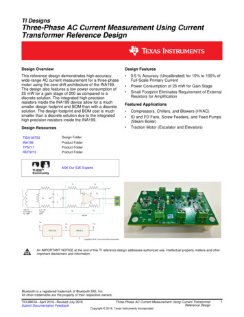
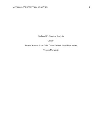
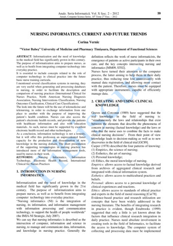
History and Current Situation of Multi-Tasking Machine ToolsAkimitsu Nagae1,Toshiyuki Muraki1,Hiromasa Yamamoto11Yamazaki Mazak Corporation, Japan[Received November 16, 2012; Accepted October 09, 2012]AbstractManufacturing industries are in intense global competition, and stricter demands for reduction in costand total in-process time increase year after year. As a result, a production system that can produce awide variety of components in small lot sizes in response to fluctuations in demand with small floorspace requirements is strongly demanded. Our company has been responding to this challenge byprocess integration and high-efficiency machining methods using multi-tasking machine tools. In thisarticle, we describe the development and history of such multi-tasking machines as well as examplesof workpieces processed by this type of machine tool and examples of recently developed newfunctions.Keywords: Multi-tasking Machine Tool, High productivity, Done-in-One1 INTRODUCTIONManufacturing industries are in intense globalcompetition, and stricter demands for reduction in costand total in-process time increase year after year. As aresult, a production system that can produce a widevariety of components in small lot sizes in response tofluctuations in demand with small floor spacerequirements is strongly demanded. Our company hasbeen responding to this challenge by process integrationand high-efficiency machining methods using multitasking machine tools.Since multi-tasking machine tools have both functions ofturning (the same as turning centers) and machining (thesame as 5-axis simultaneously controlled machiningcenters which perform milling, end milling, boring,tapping, etc.), machining processes requiring multipleturning centers and/or machining centers can beintegrated and run on a single multi-tasking machine.This article will presents the development and history ofsuch multi-tasking machines as well as examples ofworkpieces processed by this type of machine tool andexamples of recently developed new functions.2 HISTORY OF MULTI-TASKING MACHINE TOOLSMulti-tasking machine tools have been developedoriginally from lathes. That is, normal lathes CNClathes Multi-tasking lathes Multi-tasking machinetools (lathe-based) Multi-tasking machine tools(machining center-based). (See Figure 1.) The principaldifference between multi-tasking lathes and multi-taskingmachine tools (lathe-based) lies in their milling capacity.During the development of multi-tasking lathes, thediameter of the milling spindle was small, it was thoughtthat multi-tasking capacity limited to small-diameterdrilling and tapping was adequate for multi-tasking lathes.But for multi-tasking machine tools (lathe-based), aspindle of 70mm or larger in diameter with sufficientmilling capability to perform milling and also end millingwas required. Unless multi-tasking machine tools havethis milling capacity, machining by a machining center in afollowing process would be necessary. As a result,process integration was not sufficiently realized in manycases.On the other hand, multi-tasking machine tools(machining center-based) have recently appeared on themarket. These machines allow milling and turning ofextremely-large-diameter workpieces which used to betransferred to a machining center for milling aftercompletion of turning. Performing all processes on asingle machine results in a significant reduction of inprocess time.3MULTI-TASKING MACHINE TOOL STRUCTUREAND APPLICABLE PARTSThe typical structure of multi-tasking machine tools (lathebased) is shown in Figure 2. It consists basically of 5axes: 3 linear axes (X,Y and Z), a rotary C axis of theturning spindle, and a rotary B-axis around the Y-axis. Inaddition, if the machine has a second turning spindle, itFigure 1: History of multi-tasking machine tools Journal of SME-Japan
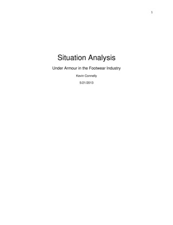
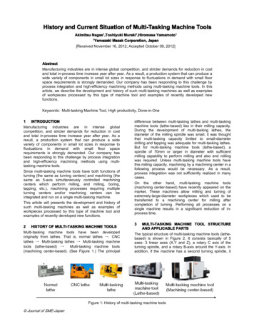
consists of three rotary axes, and the Z-axis of the spindlewhich moves in the Z direction is added. Moreover, if themachine has a second turret, Z- and X-axis movements ofthe turret are added. A representative example ofmachining by a multi-tasking machine tool with such astructure is shown in Figure 3.A typical structure of multi-tasking machine tools(Machining center-based) is shown in Figure 4. This is amachine with a horizontal machining center table whoserotational speed is increased to about 600rpm. Variousmachining processes such as turning can be performedby various tools mounted in the milling spindle which canswing in the B-axis direction. Having a ram spindle whichcorresponds to the second turret of multi-tasking machinetools (lathe-based) allows workpiece I.D. machining. Arepresentative example of a workpiece machined by amulti-tasking machine tool with such a structure is shownin Figure 5.Figure 4: Structure of multi-tasking machine tool(Machining center-based).Figure 2: Structure of multi-tasking machine tool (Lathebased).Figure 5: Examples of machining by multi-taskingmachine tool (Machining center-based).Figure 3: Parts shaped by machining by multi-taskingmachine tool (lathe-based).4 ADDITION OF NEW FUNCTIONMulti-tasking machine tools have been developed tointegrate lathe and machining center processes. With therecent development of machines having advancedfunctions, multi-tasking machines are now capable ofspecial machining which was previously considered asprocesses that were difficult to integrate. (See Figure 6).On the other hand, workpieces of difficult to machinematerials increased, and there has been a challenge toFigure 6: Process integration by multi-tasking machine tool including special machining Journal of SME-Japan
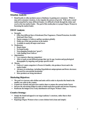
reduce their machining time. Examples of processintegration and highly-efficient machining methods inwhich the advantages of multi-tasking machine tools withadvanced functions are utilized are shown below:4.1 Deep Boring by Long Boring BarFor aircraft landing gear (landing wheel struts)components, deep boring is required. For many deepboring applications, dedicated machines have previouslybeen used because it is difficult to machine them bygeneral-purpose machines.A long boring bar system for such deep boring processesfor multi-tasking machine tools is introduced here. Thislong boring bar is hydraulically clamped to the Y-axislower saddle with a construction that ensures sufficientrigidity. (Figure 7). Three long boring bars that can bore a1000mm deep can be stored in a dedicated stocker. Theinserts of some boring bars can be automaticallyreplaced.Figure 8: Deep-hole milling with high-rigidity special toolholder4.3 Taper Boring by U-axis ToolIn tapered bore (conically shaped hole) machining ofvalve-related components, a fine finished surface isnormally required for the purpose of high sealing property.Normally, tapered-hole boring cannot be performed by themilling spindle; however, it can be performed using aspecial U-axis tool. The U-axis tool has a control axis (Uaxis) in the radial direction of the tool spindle, and the tipof the tool can be controlled in the radial direction whilethe milling spindle is rotating (Figure 9). Complex innertaper or curved surfaces can be finished with highaccuracy by the U-axis tool.Figure 9: Boring by U-axis tool (D’andrea TA-C160)Figure 7: Deep-hole boring by long boring bar4.2 Deep-hole Milling with Special High-rigidity ToolHolderKeyway milling in deep-bores is difficult to be performedby a normal angle tool. For such deep-hole milling, aspecial high-rigidity tool holder for process integration bymulti-tasking machine tools was developed (Figure 8.).This special high-rigidity tool holder is clamped at fourlocations on the tool spindle surface and has a highrigidity structure to withstand deep-hole milling. Thisspecial high-rigidity tool holder is stored in a dedicatedstocker and automatically loaded/unloaded to/from thetool spindle.4.4 HobbingComponents found in many industries – such as jetengines, energy, construction machinery and others, havegears integrated on shafts. Gear teeth are normallymachined by dedicated machine tools such as gearhobbing machines. Gear hobbing can be performed bymulti-tasking machines by synchronizing the spindlerotation with that of the milling spindle (Figure.10).Figure 10: Hobbing in turning spindle-tool spindlesimultaneous control4.5 Grinding of Turbine Blades Journal of SME-Japan
Up to thousands of turbine blades are required for one jetengine or gas turbine. For this reason, higher productivityand automation are strongly demanded for thesecomponents.5-axis simultaneous machining by multi-tasking machinetools has been widely applied in machining of materials toproduce turbine blades. In the future, by performing notonly cutting but also grinding by multi-tasking machinetools, it is expected that automated grinding and otherprocesses can be integrated into a multi-tasking machinetool (Figure.11). In addition, by integrating all processesinto a single machine, changes in blade shapes andproduction lot sizes can be handled with much flexibility.In addition, supplying grinding lubricant through thegrinding wheel would minimize grinding burns andmaterial clogging the grinding wheel to realize improvedgrinding accuracy.electric discharge machining and cutting at the sametime, it is anticipated that a single machine can produce 2disks a day while performing continuous unmannedmachining.Figure 12: Electric discharge machining of turbine disk(Photo provided by: Tokyo University of Agriculture andTechnology, Chiyoda Kinzoku)Figure 11: Grinding of turbine blade(Photo provided by: Tokyo University of Agriculture andTechnology, NASADA Co. Ltd.)4.6 Electric Discharge Machining of Turbine DisksIn addition to turning and boring operations, turbine disksrequire the broaching of a complex shape (Christmastree) on the outer diameter where the turbine blades aremounted. This broaching requires a large dedicatedmachine tool and a dedicated broach.Figure 12 shows a multi-tasking machine tool with thecapacity for both cutting and electric discharge machiningto integrate all these processes required for themachining of turbine disks. A tank and an electricdischarge unit having wire guide unit, etc. are installed inthis multi-tasking machine tool. Turning and boring areperformed on a workpiece and in the same setup, electricdischarge machining is performed on the disk outerdiameter to cut the complex shape. Research isunderway regarding finish machining of this complexshape by endmilling. This would allow after roughmachining is performed by electrical discharge machining,the disc could be indexed for finish machining by themulti-tasking machine milling spindle. By performing4.7 Turning Tools with Round InsertsBy performing turning operations with round inserts onmulti-tasking machine tools, the B-axis can be used tochange the tool rake angle during each cutting pass. Bydoing so, heat generated by cutting is better dissipatedand tool life is extended. By applying minute quantities ofoil-mist to the tool tip, tool wear and built-up edge areminimized. It is anticipated that this will allow cutting ofheat-resistant Inconel alloy 718 (HRC45) up to 10 timesfaster than conventional processing (Figure 13).Figure 13: Rotary cutting Journal of SME-Japan
4.8 Mill-TurningMill-Turning is performed by using a rotating milling cutterinstead of a normal turning tool (Figure 14). The cutterrotates during cutting, then as with rotary cutting, the tooltip can be cooled while air cutting as well as reducing toolwear. High-efficiency machining can be realized byrotating the tool at high speed even if the workpiece is notrotated at a high speed, which is extremely beneficial forheavy-duty cutting of unbalanced workpieces as well asintermittent cutting. Additionally, this ensures the breakingof the machined chip for difficult to machine materials.More research is required to determine the optimumcutting conditions for these two machining process.Figure 14: Mill-Turning5 CLOSINGIn this article, the history and structure of multi-taskingmachine tools and how they are used recently have beenintroduced. A review of the history shows that a reductionof the total production lead time – from supply of rawmaterial to the finished product, has been realized.Therefore, as long as there continues to be strongcustomer demands for higher efficiency, the evolution ofmulti-tasking machines will continue in the future resultingin further improvements in productivity.REFERENCES[1] Report on results of support project of advancementof strategic basic technology in fiscal 2011 “Study ofadvancement of machining technology of difficult-tomachine components in complex shape of gasturbine engine” (in Japanese)[2] Report on results of support project of advancementof strategic basic technology in fiscal 2011“Development of hybrid machining technology of jetengine turbine disks without machining strain (inJapanese)[3] YAMAMOTO Hiromasa, SATAKE Kentaro, SAHARAHiroyuki, NARITA Toru, TSUTSUMI Masaomi, &MURAKI Toshiyuki. Effectiveness of MQL on highefficient machining of difficult-to-machine materialsby rotary cutting: Journal of The Japan Society forPrecision Engineering, 77, 3 (2011),316-321 (inJapanese)[4] OKUDA Toshihito, MURAKI Toshiyuki, NAKAYAMATatsuomi, & OTA Minoru: Development of dry turnmilling with multi-blade cutter for alloy steels Journal of SME-Japan(Advanced machine tool), Proceedings of LEM 21(2005) 433-438
Yamazaki Mazak Corporation, Japan [Received November 16 ,20 12 ;A ccepted October 09 ,20 12 ] . Examples of process integration and highly-efficient machining methods in which the advantages of multi-tasking machine tools with advanced functions are utilized are shown below: 4.1 Deep Boring by Long Boring Bar For aircraft landing gear (landing wheel struts) components, deep boring is .