Transcription
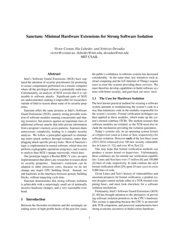
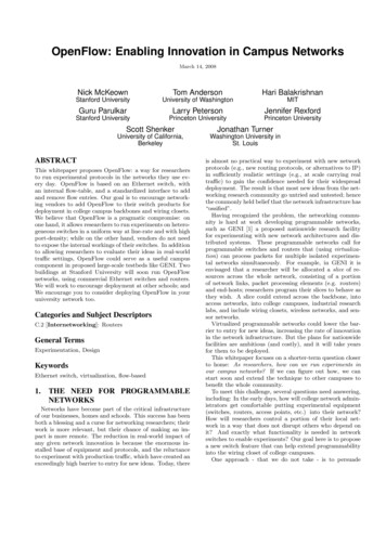
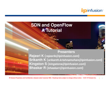
Extensionss to OpennFlow Prootocol in support Circuit SwwitchingAddeendum to OpenFlow Prootocol Speciffication (v0.88.9) – Circuitt Switch Adddendum v0.22Auguust 22nd, 2009Current Maintainer: Saurav Das (sdd2@stanford.edu)1. Introoductionbes the requirrements of ann OpenFlow circuitcswitch. We recommmend that youu readThis document describo the OpenFlow switch specificationn for packett switches ono the OpennFlowthe version v0.8.9 ofConsortiuum website (hhttp://OpenFFlowSwitch.orrg). This speccification covvers the compponents and basicfunctions of circuit switches based on switchingg time‐slots, wavelengthswa fibers. It also covers hybridandhswitches such as packket switches with circuit interfaces annd converselly circuit switches with packetpinterfacess. Accordingly this documment specifies OpenFlow protocol changes required to managee suchOpenFloww switches froom a remote controller. ThisT documennt should be viewedvas an addendum tot theswitch speecification for packet switches and not independenttly.2. Swittch CompoonentsAn OpenFFlow circuit switchsconsistts of a cross‐‐connect tablle, which cacches the inforrmation abouut theexisting circuitcflows (or cross‐connnects madee in the swittch), and a secureschannnel to an extternalcontrollerr, which manaages the switch over the secure channeel using the OpenFlowOprootocol.The circuit switch floww table (crosss‐connect taable) containss a set of cirrcuit flow entries, which detailwhich inpput channels are cross‐connnected to which output channelsc(Fig. 1). Additionnally it maintaains 1or more actions for eachecircuit fllow, details ofo which will be explained in followinng sections. Lastly,Lmstattistics for the flow.where appropriate it maintainsFigg. 1: Circuit flow taable (cross‐conneect table) entryUnlike an OpenFlow packet switch,, the cross‐coonnect table isi not used too lookup flowws, as circuits portstypically havehno visibbility into packets (the paayload). Typiically there iss no bufferinng within a circuitcswitch (ooptical or eleectronic). Acccordingly no packets are forwarded tot the controller as welll. Thecontrollerr is responsible for provisiooning and remmoving conneections in an OpenFlow cirrcuit switch via theextensionns to the OpeenFlow protoocol for suppporting circuit switching. Some moderrn circuit swiitchesinclude packetpinterfaaces and can switch packets electroonically, or sendsthem outo of the circuitcinterfacess. Such switchhes should maaintain separate packet annd circuit floww tables as shown in Fig. 2a.
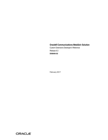
Fig 2(a) An OpenFlowOswitch withw packet and ciircuit hardware flow tables;2(bb) Various ways too interconnect paccket and circuit swwitchesFig. 2b shows various wayswto intercconnect packket and circuitt switches:pswitchh P is conneected to the TDM circuit switch C via a Packet overoSONET (POS)1. The packetinterfface. The SONNET switches (DXC) are connnected to eaach other oveer static DWDM line systemms.2. The same as choicce I, but noww the P is connnected to a TDM C via ann Ethernet innterface. C haas thecapabbility to adaptt IP packets frrom the Ethernet interfacee to SONET frraming.3. P is now connected via an OXC such a fiber crossconnectt. POS framinng is used on the packet swwitch.This interface on thet packet swwitch does noot use high quuality transceeivers neededd for long disstancecommmunications neither doess it use thee standardizeed ITU grid wavelengths– hence DWWDMtranspponders are needednbeforre the signal is transmittedd over the DWWDM line systtems.4. The packetpswitchh now uses DWDMDtranscceivers (with suitable framing). The wavelengthwon thetransmmitters may evenebe tunable. The static DWDM linee system has now been reeplaced with moremodeern ROADM/WWSS based OXXCs.5. Lastlyy, this configuuration showss that the actual situation could be a coombination ofo the above. Someinterffaces on the packet switch could be connected tot TDM circuuit switches which themsselvesconneect via ROADMs. Other intterfaces can directly connnect to the OXXC via transpponders or tunableDWDMM interfaces.Definitionn of terms: TDM/ DWDM – Timee Division Multtiplexing/ Densse Wavelengthh Division Multtiplexing;SONETT/SDH – Synchronous Optical NETwork/ Synchronous Diggital Hierarchy;;DXC/OOXC – Digital Crross‐connect/ Optical Cross‐cconnect;ROADM/WSS – Recoonfigurable Opptical Add Dropp Multiplexer/ WavelengthWSeelective Switchh;VCAT//VCG/LCAS – VirtualVConcateenation/ Virtuaal Concatenatioon Group/ Linkk Capacity Adjuustment SchemmePOS/GGFP – Packet ovver SONET framming/ Generic Framing ProceedureITU – InternationalITelecommunicaTations Union
3. OpenFlow Circuit‐Switch ProtocolThe OpenFlow protocol supports three message types, controller‐to‐switch, asynchronous andsymmetric each with multiple subtypes. In general, we maintain the same message types for a circuitswitch but change some of the structures used in the message. As mentioned in the introduction, thisspec should not be viewed as independent of the packet switching spec. This spec extends structs andmessages used in the packet spec. We first summarize the changes we have made to the packetswitching spec v0.8.9 and then give details in subsequent sections.3.1 Changes to OpenFlow packet switching spec v0.8.91. Changes to the capabilities field in struct ofp switch features to account for circuit switchcapabilities not found in regular packet switches (Sec. 3.2).2. Extension of struct ofp phy port to account for circuit port characteristics (Sec. 3.3)3. Definition of struct ofp connect for specifying the cross‐connection in circuit switches. Thisstruct is the logical equivalent of struct ofp match in the packet spec (Sec. 3.4)4. OpenFlow messages: this addendum defines one additional message to enum ofp type –OFPT CFLOW MOD and one additional flow mod command OFPFC DROP (Sec. 3.5)5. Addition of two action types OFPAT CKT OUTPUT and OFPAT CKT INPUT to account foradapting packet flows to circuit flows and extracting packet flows from circuit flows (Sec. 3.6)6. Addition of error messages to inform controller of problems in circuit switch configuration (Sec.3.7)3.2 Switch FeaturesUpon SSL session establishment, the controller sends an OFPT FEATURES REQUEST message. Thismessage does not contain a body beyond the OpenFlow header. The switch responds with anOFPT FEATURES REPLY message:/* Switch features. */struct ofp switch features {struct ofp header header;uint64 t datapath id;/* Datapath unique ID. Only the lower 48-bits are meaningful. */uint32 t n buffers;uint8 t n tables;uint8 t pad[3];/* Max packets buffered at once. *//* Number of tables supported by datapath. *//* Align to 64-bits. *//* Features. */uint32 t capabilities;uint32 t actions;/* Bitmap of supported "ofp capabilities". *//* Bitmap of supported "ofp action type"s. *//* Port info.*/struct ofp phy port ports[0]; /* Port definitions. The number of ports is inferred fromthe length field in the header. */};OFP ASSERT(sizeof(struct ofp switch features) 32);
For an OpenFlow circuit switch, we maintain the same switch features struct used for OF packetswitches. However we expand the capabilities field to include the following:/* Capabilities supported by the datapath. */enum ofp capabilities {OFPC FLOW STATS 1 0, /* Flow statistics. */OFPC TABLE STATS 1 1, /* Table statistics. */OFPC PORT STATS 1 2, /* Port statistics. */OFPC STP 1 3, /* 802.1d spanning tree. */OFPC MULTI PHY TX 1 4, /* Supports transmitting through multiple physical interfaces */OFPC IP REASM 1 5, /* Can reassemble IP fragments. *//* following capabilities are defined for circuit switches*/OFPC CTG CONCAT 1 31, /* Support for contiguous concatenation on all TDM ports */OFPC VIR CONCAT 1 30, /* Support for virtual concatenation (VCAT) on TDM ports*/OFPC LCAS 1 29, /* Support for Link Capacity Adjustment Scheme (LCAS) */OFPC POS 1 28, /* Support for Packet over Sonet (PoS) adaptation */OFPC GFP 1 27, /* Support for Generic Framing Procedure (GFP) adaptation */OFPC 10G WAN 1 26 /* Support for native transport of 10GE WAN PHY on OC-192 */};3.3 Port StructurePhysical ports are reported as part of an array of struct ofp phy port in the OFPT FEATURES REPLYmessage. This spec extends the definition of phy ports – here we make a small concession: we use thisstruct to define switch internal ports and configured virtual ports as well as regular phy ports. In theinterest of staying true to the packet switching spec, we retain the name ofp phy port./* Description of ports */struct ofp phy port {uint16 t port no;uint8 t hw addr[OFP ETH ALEN];uint8 t name[OFP MAX PORT NAME LEN];uint32 t config;uint32 t state;/* 00:00:00:00:00:00 if not an Ethernet port *//* Null-terminated*//* Bitmap of OFPPC * flags *//* Bitmap of OFPPS * flags *//* Bitmaps of OFPPF * that describe features. All bits zeroed if* unsupported or unavailable. */uint32 t curr;/* Current features. */uint32 t advertised;/* Features being advertised by the port. */uint32 t supported;/* Features supported by the port. */uint32 t peer;/* Features advertised by peer. */uint16 tunit16 tuint32 tuint32 tuint8 tunit64 tuint64 tsupp swtype;peer swtype;supp sw tdm gran;peer sw tdm gran;pad[4];bandwidth1;bandwidth2;/* Bitmap of switching type OFPST * flags *//* Bitmap of peer’s switching type *//* TDM switching granularity OFPTSG * flags *//* peer’s TDM switching granularity *//* Align to 64 bits *//* Bitmap of the OFPCBL * or OFPCBT * flags *//* Same type as bandwidth1 */};OFP ASSERT(sizeof ( struct ofp phy cport) 80);
The port number is a value that the datapath associates with a physical port. The port numbers usagehas been changed to account for additional port types:/* Port numbering. Physical ports are numbered starting from 0. */enum ofp port {/* Max number of real Ethernet and TDM ports – 0xfa00 (0x0000 to 0xf9ff)*//* Switch internal ports - 0xfa00 to 0xfaff *//* Switch virtual circuit ports - 0xfb00 to 0xfeff*//* Other virtual ports – 0xff00 to 0xffff*/OFPP MAX/* Fake output "ports". */OFPP IN PORTOFPP TABLEOFPP NORMALOFPP FLOODOFPP ALLOFPP CONTROLLEROFPP LOCALOFPP NONE}; 0xfa00, 0xfff8, /* Send the packet out the input port. Thisvirtual port must be explicitly usedin order to send back out of the input port. */ 0xfff9, /* Perform actions in flow table.NB: This can only be the destinationport for packet-out messages. */ 0xfffa, /* Process with normal L2/L3 switching. */ 0xfffb, /* All physical ports except input port andThose disabled by STP. */ 0xfffc, /* All physical ports except input port. */ 0xfffd, /* Send to controller. */ 0xfffe, /* Local openflow "port". */ 0xffff /* Not associated with a physical port. */The only change made from the OpenFlow packet switch specification is that we have limited thenumber of physical ports to 0xfa00 instead of 0xff00 and used the numbers in between to specifyinternal and virtual ports used in circuit switches. These internal port numbers can be used to specify“mapper” ports that map Ethernet packets to TDM time‐slots, while the virtual ports can be used todefine Virtual Concatenation Group (VCG) numbers used for VCAT technology in TDM switches.The hardware address is the Ethernet address of the port for Ethernet ports, and is zeroed out for othertypes of ports (SONET/Wavelength) in circuit switches. The name field is a null terminated stringcontaining a human readable name for the interface. In packet switches, examples are eth0, eth1 etc. Incircuit switches, it can correspond to the standard Rack‐Shelf‐Slot‐Port designation for telecomequipment. The config and state fields are currently the same as described in the OpenFlowspecification for packet switches. The features bitmap has been modified to include line‐rates intransport networks./* Features of physical ports available in a datapath. */enum ofp port features {OFPPF 10MB HD 1 0, /* 10 Mb half-duplex rate support. */OFPPF 10MB FD 1 1, /* 10 Mb full-duplex rate support. */OFPPF 100MB HD 1 2, /* 100 Mb half-duplex rate support. */OFPPF 100MB FD 1 3, /* 100 Mb full-duplex rate support. */OFPPF 1GB HD 1 4, /* 1 Gb half-duplex rate support. */OFPPF 1GB FD 1 5, /* 1 Gb full-duplex rate support. */
OFPPF 10GB FDOFPPF COPPEROFPPF FIBEROFPPF AUTONEGOFPPF PAUSEOFPPF PAUSE ASYM 1 6, /* 10 Gb full-duplex rate support (10.3125 Gbps LAN PHY). */ 1 7, /* Copper medium */ 1 8, /* Fiber medium */ 1 9, /* Auto-negotiation */ 1 10, /* Pause */ 1 11, /* Asymmetric pause *//* The following have been added for WAN interfaces*/OFPPF X 1 20, /* Don’t care – applicable to fiber switch ports */OFPPF OC1 1 21, /* 51.84 Mbps OC-1/STM-0 */OFPPF OC3 1 22, /* 155.52 Mbps OC-3/STM-1 */OFPPF OC12 1 23, /* 622.08 Mbps OC-12/STM-4 */OFPPF OC48 1 24, /* 2.48832 Gbps OC-48/STM-16 */OFPPF OC192 1 25, /* 9.95328 Gbps OC-192/STM-64 */OFPPF OC768 1 26, /* 39.81312 Gbps OC-768/STM-256 */OFPPF 100GB 1 27, /* 100 Gbps */OFPPF 10GB WAN 1 28, /* 10 Gbps Ethernet WAN PHY (9.95328 Gbps) */OFPPF OTU1 1 29, /* OTN OTU-1 2.666 Gbps */OFPPF OTU2 1 30, /* OTN OTU-2 10.709 Gbps */OFPPF OTU3 1 31 /* OTN OUT-3 42.836 Gbps */};The above line rates are OCs (SONET standard) and their corresponding STMs (SDH standard). OpticalTransport Network (OTN, G.709, digital wrapper) data rates have been added above as placeholders –this specification does not currently support OTN. The swtype fields are defined as:/*Switching type of physical ports available in a datapath. */enum ofp port swtype {OFPST L4 1 0, /* Capable of switching packets based on TCP or UDP headers*/OFPST IP 1 1, /* Capable of switching packets based on IP headers */OFPST MPLS 1 2, /* Capable of switching packets based on MPLS labels*/OFPST VLAN 1 3, /* Capable of switching packets based on VLAN tags */OFPST ETH 1 4, /* Capable of switching packets based on Ethernet headers */OFPST T SONET 1 11, /* Capable of switching circuits (timeslots) based on SONET standard */OFPST T SDH 1 12, /* Capable of switching circuits (timeslots) based on SDH standard */OFPST T OTN 1 13, /* Capable of switching circuits (timeslots) based on OTN standard */OFPST WAVE 1 14, /* Capable of switching circuits (wavelengths) based on ITU-T grid wavelengths */OFPST FIBER 1 15 /* Capable of switching circuits (fibers) */};An OpenFlow packet switch can switch flows on the basis of Ethernet, IP, VLAN and transport layerheaders. Such a switch will set multiple bits above. This specification does not currently support MPLSlabel switching or TDM switching based on OTN frame formats. The sw tdm gran fields are defined as:/* Minimum switching granularity of TDM physical ports available in a datapath. */enum ofp port tdm gran{OFPTSG STS 1,/* STS-1/STM-0 */OFPTSG STS 3,/* STS-3/STM-1 */OFPTSG STS 3c,/* STS-3c/STM-1*/OFPTSG STS 12,/* STS-12/STM-4 */OFPTSG STS 12c,/* STS-12c/STM-4c */OFPTSG STS 48,/* STS-48/STM-16 */OFPTSG STS 48c,/* STS-48c/STM-16c */OFPTSG STS 192,/* STS-192/STM-64 */OFPTSG STS 192c,/* STS-192c/STM-64c */
OFPTSG STS 768,OFPTSG STS 768c/* STS-768/STM-256 *//* STS-768c/STM-256c */}The STS‐*c signal bits should only be set if the switch supports contiguous concatenation in the switchcapabilities. Note that the OpenFlow protocol does not support TDM signals smaller than STS‐1 –i.e. noSONET VT’s or SDH LOVC’s are supported.The bandwidth1 and bandwidth2 fields of the ofp phy cport struct need to be explained in moredetail. Their purpose is to flexibly indicate the bandwidth supported and currently used/available by thecircuit port. Their interpretation depends on the switching type of the switch port. If the switching type of the port (defined in the supp swtype field) is OFPST WAVE, thenbandwidth1 and bandwidth2 are bitmaps corresponding to the OFPCBL * flags. Additionally,bandwidth1 identifies the wavelengths supported by the switch and bandwidth2 identifies thewavelengths currently under use (ie. cross‐connected) If the switching type of the port is OFPST T SONET or OFPST T SDH, then bandwidth1 andbandwidth2 identify available time slots for various TDM signals. Depending on the line‐rate, wedefine different interpretations of the bits in the 64‐bit field below. Note that we do not need one ofthe fields to identify supported time‐slots as that can be inferred from the line‐rate and TDMswitching granularity.For a switching type of OFPST WAVE, bandwidth 1 has the following meaning: The lower 10 bits of the64 bit uint64 t will be used for flags with special meaning. The upper 54 bits will be used to designateITU‐T grid frequencies supported by the switch port./*Switching granularity of TDM physical ports available in a datapath. */enum ofp port lam bw{OFPCBL X 1 0, /* 1 if fiber switch – don’t care what wavelength is used, 0 if lambda switch */OFPCBL 100 50 1 1, /* 1 if 100GHz channel spacing, 0 if 50 GHz */OFPCBL C L 1 2, /* 1 if C –band, 0 if L-band */OFPCBL OSC 1 3, /* 1 if supporting the OSC at 1510nm, 0 if not */OFPCBL TLS 1 4 /* 1 if using TLS, 0 if not */};Bits 5 through 9 are reserved for future use. In a 100 GHz channel spaced system, the bits 10‐63 are asfollows: bit 10 corresponds to 196.7 THz (1524.11 nm), bit 11 to 196.6 THz, bit 12 to 196.5 THz and soon, with bit 63 corresponding to 191.4 THz (1566.33 nm). In an L‐Band system, bit 10 would correspondto 190.7 THz (1572.06 nm) and bit 63 to 185.4 THz (1617.08 nm).bandwidth1 and bandwidth2 fields:
Although bit 1 is used to identify a 100GHz systtem or a 50GGHz system, this specification currentlyy doesnot suppoort a 50GHz spaced systeem. Bit 2 ideentifies a C or L band system. A waveelength switch hasmux/demmux filters that are designeed to operatee in either thee C or L bandss but not both. Accordinglly thisbit indicates whether the flags in bit 10‐63 coorrespond to C or L band wavelengthss. Bit 0 is used toidentify a fiber switchh as opposed to a waveleength switch which can distinguish beetween and switchswavelengths individuaally. A fiber switch is typpically agnostic to whateever signals area carried in theincoming fiber and thhus a ‘don’t care’ applies in this casee. However iff a fiber swittch is used withw atranspondder on the poort, then the switch port shouldsbe treated as a wavelength swittch port (bit 0 0,one of bitts 10‐63 should be set, andd the line‐ratee flag OFPPF * should be set).sAnother relevantrsituaation is with regards to a wavelengthh switch used in a systemm where diffferentwavelengths support different linee‐rates. For example,ein a 40 channel C‐band systtem, it is possibleuthat some waveleengths have transceiverstoat 10 Gbps.(though unlikely)running at 2.5 Gbps and othersWhile it maym seem thaat a wavelength switch shhould be agnnostic to the line‐rate akinn to fiber swiitches, this is not always truee. This is beccause waveleength switches have filteers towithout transponderstmux/demmux wavelenggths and thesse filters have passband widthswdesignned for a cerrtain line‐ratee andchannel spacing. Whilee a filter desiigned for 10 Gbps signal canc pass a 2.55 Gbps signall (albeit with morecpass a 40 Gbps signnal. Thus for a wavelengthh switch, we neednto speciify for the port thenoise) it cannothighest linne‐rate it can support withh the OFPPF * flags.Bit 3 is used to identifyy the Optical Supervisory ChannelC(OSCC‐typically at 15101nm) which is convertted tothe electrical domain, processed and then ree‐converted tot the opticaal domain foor transmission (aprocess known as OEOO). Bit 4 is useed to identify a Path Terminating Equipmment (PTE) whichwhas a tunablelaser sourrce (TLS) on thhe output port. In this case, the bandwwidth1 field identifies the tuning range ofo theTLS and thet bandwidtth2 field idenntifies the currrent laser wavelength.wNote that the TLS must supportITU grid wavelengths.wAlso our use of ‘PTE’ heree signifies equipment thatt adapts packkets to circuitts andvice versaa – for eg.
OpenFlow c specification g). This spec time‐slots, w interfaces an s OpenFlow his documen independent ircuit switch. for packet ification cov avelengths a d conversel protocol cha t should be v ly. We recomm switches o ers the comp nd fibers. It y circuit swi nges require iewed as an end that you n the Open