Transcription
Deployment GuideBlue Coat CacheFlowTransparent Cache SwitchingDG BC CacheFlow 062013.1
Deployment Guide—Thunder / AX Series for Blue Coat CacheFlow TCSTABLE OF CONTENTS1Introduction . 32Deployment Guide Overview . 33Deployment Guide Prerequisites . 34Accessing the ACOS Device . 45Architecture Overview . 45.1Traffic WorkFlow: HTTP Request . 55.2Traffic Workflow: HTTP Response . 66Configuration . 67Health Monitor Configuration . 78Server Configuration . 89Service Group Configuration . 910Access List Configuration . 1111Virtual Server Configuration . 1212Summary and Conclusion . 15A.CLI Commands for ACOS Configuration . 152
Deployment Guide—Thunder / AX Series for Blue Coat CacheFlow TCS1INTRODUCTIONThe demand for bandwidth has increased drastically over recent years, as megabyte-hungry Web 2.0technology and mobile devices insatiably consume new capacity as soon as it becomes available.According to TeleGeography, a global bandwidth research service, the demand for internationalbandwidth grew 45 percent in 2011, while the compounded rate of growth was 57 percent annuallybetween 2007 and 2011. In addition, rich media content has increased and the migration of traditionaltelevision content to the Internet is accelerating the demand for more bandwidth.Blue Coat CacheFlow appliances provide a high performance caching solution that enables serviceproviders to manage the drastic increase in network traffic and rapid subscriber growth. Utilizing highlyeffective Web caching technology, CacheFlow appliances save bandwidth on expensive internationallinks and backhaul traffic, while improving the end-user Web experience.To maximize the efficiency of the CacheFlow devices, the A10 Thunder Series and AX Series ApplicationDelivery Controllers (ADCs) can balance the traffic flows for Blue Coat CacheFlow appliances.2DEPLOYMENT GUIDE OVERVIEWThis deployment guide shows how to install and deploy the A10 ADC with Blue Coat CacheFlow cachingappliances. The deployment guide focuses on how end-user HTTP (80) requests can be served usingTransparent Cache Switching (TCS) with the Thunder Series and AX Series ADCs. The configurationsections show how to deploy load balancing , health monitoring, DDoS protection, and device persistencefor each traffic flow for Blue Coat CacheFlow appliances.3DEPLOYMENT GUIDE PREREQUISITESThis Blue Coat CacheFlow integration was tested with the following setup:A10 tested configuration: The A10 Networks ADC must be running ACOS version 2.7.x or higher Blue Coat CacheFlow integration was tested with AX Series hardware-based appliances, as wellas SoftAX virtual appliances. Blue Coat CacheFlow appliance requirements: Blue Coat CacheFlow 5000 CacheFlow Release 3.2.2.3 or higher3
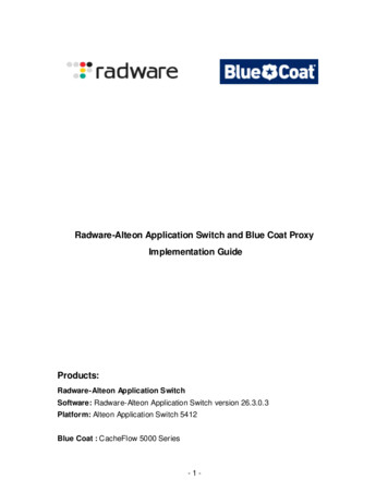
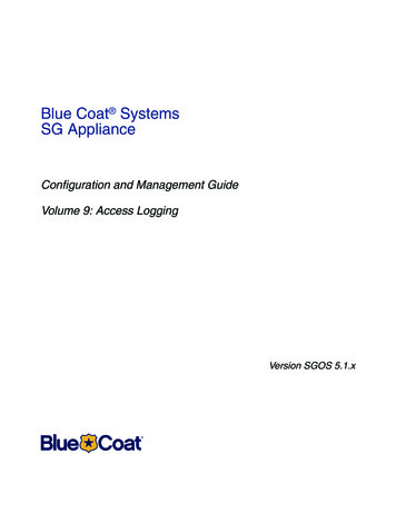
Deployment Guide—Thunder / AX Series for Blue Coat CacheFlow TCSNote: The features described in this guide are supported in Thunder Series and AX Series devices.Testing was performed using an AX device.4ACCESSING THE ACOS DEVICEThis section describes how to access the AX Series device from a Command Line Interface (CLI) orGraphical User Interface (GUI): CLI – The CLI is a text-based interface in which you type commands on a command line. You canaccess the CLI directly through the serial console or over the network using either of the followingprotocols: Secure protocol – Secure Shell (SSH) version 2 Unsecure protocol – Telnet (if enabled)GUI – This is a web-based interface in which you click buttons, menus and other graphical iconsto access the configuration or management pages. From these pages, you can type or selectvalues to configure or manage the device. You can access the GUI using the following protocol: Secure protocol – Hypertext Transfer Protocol over Secure Socket Layer (HTTPS)Note: HTTP requests are redirected to HTTPS by default on the AX device.Default Access Information: Default Username: “admin” Default password: “a10” Default IP Address of the device: “172.31.31.31”For detailed information on how to access the AX Series device, refer to the System Configuration andAdministration Guide.5ARCHITECTURE OVERVIEWThe figure below shows a simplified topology for the A10-Blue Coat solution. The deployment of the BlueCoat CacheFlow appliance is simple, with no modification required to the subscriber's browser or otherapplications. Request traffic is redirected from the AX device to the next available Blue Coat CacheFlowappliance based on the load balancing algorithm; or, in the event of cache server outage, traffic will beredirected transparently back to the source server (Internet).4
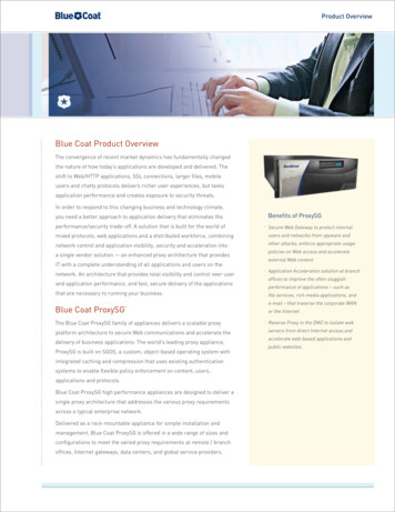
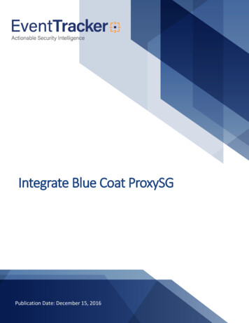
Deployment Guide—Thunder / AX Series for Blue Coat CacheFlow TCSFigure 1: Architecture overview5.1TRAFFIC WORKFLOW: HTTP REQUESTThis section explains the basic workflow for a subscriber request based on HTTP (port 80) traffic. Thesolution shown here can be applied to any protocol port. The most common ports used in TransparentCache Switching are port 443 (HTTPS) and port 21 (FTP).Figure 2: HTTP request5
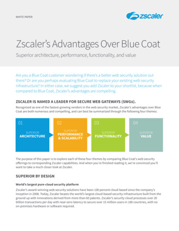
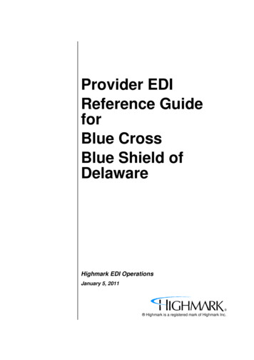
Deployment Guide—Thunder / AX Series for Blue Coat CacheFlow TCS5.2TRAFFIC WORKFLOW: HTTP RESPONSEThis section explains the HTTP response from the content servers, based on a subscriber's request.Figure 3: HTTP Response6CONFIGURATIONThis section provides detailed instructions for configuring SLB resources (real servers, service group,virtual services, and virtual services) for load balancing traffic to Blue Coat CacheFlow appliances.The tested configuration is based on “routed mode” deployment, which offers multiple benefits. It is asimple and non-intrusive installation that requires no configuration changes on the clients or the servers.In addition, the servers retain the ability to see clients' real IP addresses.When deploying an ACOS device in routed mode, there are a few points to keep in mind: The servers must use the ACOS device as their default gateway. The clients must be on a different subnet than the servers. Before you start the configuration, you must create templates, such as health monitoringtemplates.6
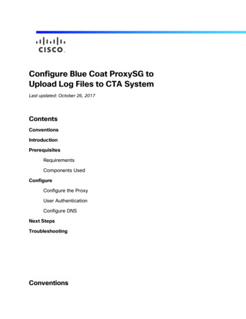
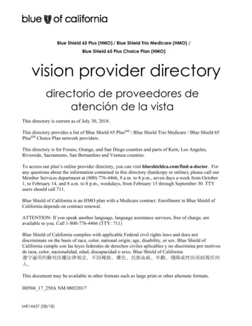
Deployment Guide—Thunder / AX Series for Blue Coat CacheFlow TCS7HEALTH MONITOR CONFIGURATIONA10 Thunder Series and AX Series ADCs can be configured to automatically initiate health status checksfor real servers and service ports. Health checks are used to assure that all requests are sent tofunctional and available servers. If a server (or a service) does not respond appropriately to a healthcheck, the server is temporarily removed from the list of available servers until it starts respondingappropriately to the health checks. At this point, the server is automatically added back to the list ofavailable servers.To configure a health check on the ACOS device:1. Navigate to Config Mode SLB Service.2. Select Add from the Health Monitor drop-down list. In the Name field, enter “tcs”.3. Select Method “HTTP”.4. Click OK, and then proceed to the next section to create a real server configuration for each BlueCoat CacheFlow appliance.Figure 4: Health monitor configuration7
Deployment Guide—Thunder / AX Series for Blue Coat CacheFlow TCS8SERVER CONFIGURATIONFollow the procedure below to create server configurations in ACOS for the Blue Coat CacheFlowappliances.1. Navigate to Config Mode Service SLB Server.2. Click Add to add a new server.3. Within the Server section, enter the following required information: Name: “cacheflow1” IP address/Host: “192.0.2.100”Note: Enter additional servers if necessary.Figure 5: Server configuration4. To add a port to the server configuration:a. Enter the port number in the Port field.b. Select the Protocol.c.Click Add.8
Deployment Guide—Thunder / AX Series for Blue Coat CacheFlow TCSFigure 6: Server port configurationNote: If you need to add additional ports, you can add it to the port list by following the same instructionsabove.5. Click OK, and then click Save to save the configuration.9SERVICE GROUP CONFIGURATIONFollow the procedure below to configure a service group.1. Navigate to Config Mode Service SLB Service Group.2. Click Add.3. Enter or select the following values: Name: "cacheflowsg" Type: "TCP" Algorithm: "Round Robin" Health Monitor: "tsc"4. In the Server section, select a server from the Server drop-down list and enter "80" in the Portfield.5. Click Add. Repeat for each server.9
Deployment Guide—Thunder / AX Series for Blue Coat CacheFlow TCSFigure 7: Service group configurationFigure 8: Server configurationNote: If you have other ports such as "443", you will be required to create another service group.6. Click OK, then click Save to save the configuration.10
Deployment Guide—Thunder / AX Series for Blue Coat CacheFlow TCS10 ACCESS LIST CONFIGUR ATIONBefore the configuring virtual server, you are required to create an Access Control List (ACL). The ACLmust use the permit action, and match on client addresses as the source address, and on the contentserver address(es) as the destination address. During configuration of the virtual server, you bind theACL to the virtual server.1. Navigate to Config Mode Security Network ACL.2. Select Extended and click Add.Enter the following values: Enter ID/Name: 102 and select ID. Select Entry. Select "Permit" from the Action area. From the drop-down menu, select "TCP". The source address and destination address will vary based on your IP addresses. Destination port must be selected:oOperator: " "oPort: "80"3. Click OK, then click Save to save the configuration.11
Deployment Guide—Thunder / AX Series for Blue Coat CacheFlow TCSFigure 9: ACL configuration11 VIRTUAL SERVER CONFIGURATIONThis section contains the configuration of a wildcard virtual server. Also known as a "Virtual IP" (VIP), thevirtual server has the IP address (VIP) that a client accesses during an initial request.1. Navigate to Config Mode Service SLB Virtual Server.2. In the General section, enter the following: Name: “cacheflowvip” Wildcard: Select the checkbox. Access List: select "102" from the drop-down menu.12
Deployment Guide—Thunder / AX Series for Blue Coat CacheFlow TCSFigure 10: Virtual server configuration3. In the Port section, click Add.4. Enter or select the following values: Virtual Server: "cacheflowvip" Type: “TCP” Port: “80” Service Group: “cacheflowsg”13
Deployment Guide—Thunder / AX Series for Blue Coat CacheFlow TCSFigure 11: Virtual-server port configuration5. In the Persistence template section, select "Destination IP Persistence Template" and select"create".6. Enter or select the following values: Name: "DST IP" Match Type: "Service Group" Timeout: "5" minutesFigure 12: Persistence configuration7. Click OK, then click Save to save the configuration.14
Deployment Guide—Thunder / AX Series for Blue Coat CacheFlow TCS12 SUMMARY AND CONCLUSIONThe sections above show how to deploy an ACOS device for optimization of Blue Coat CacheFlowdeployments. By using an ACOS device to load balance traffic across a farm of Blue Coat CacheFlowdevices, the following key advantages are achieved: Significant bandwidth reduction and improved HTTP throughput over time. In addition, thissolution can save on expensive international links and backhaul traffic, while improving the enduser Web experience. Seamless distribution of cache request traffic across multiple Blue Coat CacheFlow appliancesfor site availability and scalability. Improved site performance and reliability to subscribers by deploying DDoS mitigation featuresfrom A10 Networks.By using the A10 Thunder Series and AX Series Application Delivery Controllers (ADCs), significantbenefits are achieved for web subscribers. For more information about Thunder Series and AX Seriesproducts, please refer to the following udies.phpA. CLI COMMANDS FOR ACOS CONFIGURATIONThis section shows the CLI commands for implementing the sample configuration described above:hostname AX3030-LABtrunk 4ethernet 7 to 8name "BRAS"!sample access-listaccess-list 102 permit tcp ipaddr 0.0.3.255 any eq 80access-list 102 permit tcp ipaddr 0.0.0.255 any eq 80access-list 102 permit tcp ipaddr 0.0.1.255 any eq 80health monitor tcsmethod http15
Deployment Guide—Thunder / AX Series for Blue Coat CacheFlow TCSip anomaly-drop drop-allslb server cacheflow1 192.168.2.100port 80 tcpslb server cacheflow2 192.168.2.101health-check tcsport 80 tcpslb service-group cacheflowsg tcphealth-check tcsmember cacheflow1:80member cacheflow2:80slb template persist destination-ip DST IPmatch-type service-groupslb virtual-server cacheflowvip 0.0.0.0 acl 102port 80 tcpname wildcard v4 102 TCP 80no-dest-nattemplate persist destination-ip DST IPendNote: The value shown in this example for the name command, under port 80 tcp is auto-generatedwhen you configure the virtual port. You can edit this string if desired.16
virtual services, and virtual services) for load balancing traffic to Blue Coat CacheFlow appliances. The tested configuration is based on “routed mode” deployment, which offers multiple benefits. It is a simple and non-intrusive installation that require