Transcription
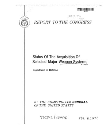
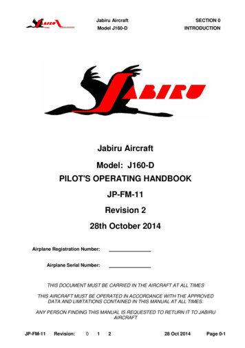
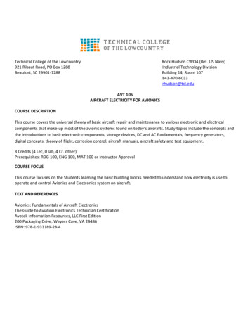
IFS ACADEMIC COURSE MANUAL5 Jan 2011A102 AIRCRAFT SYSTEMSReferences: FAA-H-8083-25A, Pilot’s Handbook of Aeronautical Knowledge, Chapters 2, 5, 6 (pgs 1-7, 10, 14-18,25-32) and 7 (pgs 1-10, 15-20, 22-26)DA20-C1 Flight Information ManualWARNINGS, CAUTIONS AND NOTES.This manual contains warnings, cautions and notes before applicable operations.WARNING: A WARNING informs the person performing the operation that injury or death is possible if they donot follow the instructions.CAUTION: A CAUTION informs the person performing the operation that damage to equipment is possible if theydo not follow the instructions.NOTE: A NOTE informs the person performing the operation how to make the task easier.INTRODUCTIONThe objective of this unit is to be able to identify and describe basic aircraft components in relation to their effecton the pilot’s operation of the aircraft. Pilots do not need to be able to design and build aircraft in order toeffectively employ the machine; however, a thorough knowledge of the aircraft allows the pilot to synthesize andevaluate sensory data to make good employment decisions. The student should know the location,nomenclature, and basic function of aircraft components and be able to describe the basic operation of aircraftsystems.IFS is conducted in the Diamond Aircraft DA20-C1, manufactured by Diamond Aircraft in London, Ontario,Canada. The DA20-C1 is comprised of five major parts: fuselage, wings, empennage (tail), landing gear, andpowerplant (engine). The framework of the airplane is called the fuselage. It is the attachment point for the othermajor components of the airplane. It also contains the cockpit, aircrew seating and baggage area. Within thecockpit are the flight controls and the instrument panel.AIRFRAMEGFRP - Glass Fiber Reinforced Plastic, CFRP - Carbon Fiber Reinforced PlasticA102-1
IFS ACADEMIC COURSE MANUAL5 Jan 2011FUSELAGEThe GFRP-fuselage is of semi-monocoque construction. The fire protection cover on the fire wall is made from aspecial fire retarding ceramic fiber that is covered by a stainless steel plate on the engine side. The mainbulkhead is of CFRP/GFRP construction. The instrument panel is made of aluminum.WINGSThe GFRP-wings are of semi-monocoque sandwichconstruction, and contain a CFRP-spar. The aileronsand flaps are made from CFRP and are attached to thewings using stainless steel and aluminum hinges.STALL STRIPA stall strip is a strip of triangular material, attached tothe leading edge of a wing. It is designed to induceturbulent airflow at higher angles of attack, resulting in astall in that particular section of the wing. It is mountedtowards the outboard section of wing, so as to maintainaileron effectiveness as long as possible. It is generallya design feature which will allow the pilot to recognize astalled condition, prior to losing aileron control, andinadvertent entry into a spin.The DA20-C1 features a triangular strip on the leading edge of the wings towards the outboard section of wing. Itlooks like a stall strip, but it is actually a vortex generator. This is designed and installed to create air vorticesover the wing surface. Vortices are generated at the inboard and outboard corners of these strips (although weare mostly interested in the inboard corner), so the sharpness of these corners is a critical factor in theeffectiveness of these strips. The intent is not just to improve airflow over the wing and aileron, but rather tocreate a boundary layer fence. This “air fence” helps delay stall propagation from the inboard section of the wing,A102-2
IFS ACADEMIC COURSE MANUAL5 Jan 2011resulting in increased aileron effectiveness in a stalled or partially stalled condition. Eventually, the angle ofattack will become high enough that the wing will stall completely, and the aileron control and effectiveness will bemarginal.EMPENNAGEThe DA20-C1 has two stabilizers. The vertical stabilizer is part of the fuselage. The aft part of the left and rightfuselage shells make the left and right shells of the vertical stabilizer. The horizontal stabilizer has top and bottomshells. Each shell has GFRP skins with a rigid foam core. The horizontal stabilizer has a main spar which holdsthe attachment bracket. Center ribs fore and aft give strength to the center area. A trailing edge web holds thehinges for the elevator. The elevator has top and bottom shells. Each shell has GFRP skins with a rigid foamcore. The rudder and elevator units are of semi-monocoque sandwich construction. The vertical stabilizercontains a di-pole antenna for the VHF radio equipment. The horizontal stabilizer contains an antenna for theNAV equipment (VOR).T-TAILIn a T-tail configuration, the elevator is above most of the effects of downwash from the propeller as well asairflow around the fuselage and/or wings during normal flight conditions. Operation of the elevator in thisundisturbed air allows control movements that are consistent throughout most flight regimes. An additional benefitis reduced vibration and noise inside the aircraft.At slow speeds, the elevator on a T-tail aircraft must be moved through a larger number of degrees of travel toraise the nose a given amount than on a conventional-tail aircraft. This is because the conventional-tail aircrafthas the downwash from the propeller pushing down on the tail to assist in raising the nose.Since controls on aircraft are rigged so that increasing control forces are required for increased control travel, theforces required to raise the nose of a T-tail aircraft are greater than those for a conventional-tail aircraft.Longitudinal stability of a trimmed aircraft is the same for both types of configuration, but the pilot must be awarethat the required control forces are greater at slow speeds during takeoffs, landings, or stalls than for similar sizeaircraft equipped with conventional tails.T-tail airplanes also require additional design considerations to counter the problem of flutter. Since the weight ofthe horizontal surfaces is at the top of the vertical stabilizer, the moment arm created causes high loads on thevertical stabilizer which can result in flutter. Engineers must compensate for this by increasing the design stiffnessof the vertical stabilizer, usually resulting in a weight penalty over conventional tail designs.When flying at a very high Angle of Attack (AOA) with a low airspeed and an aft CG, the T-tail aircraft may besusceptible to a deep stall. In a deep stall, the airflow over the horizontal tail is blanketed by the disturbed airflowfrom the wings and fuselage. In these circumstances, elevator control could be diminished, making it difficult torecover from the stall. It should be noted that an aft CG is often a contributing factor in these incidents, sincesimilar recovery problems are also found withconventional tail aircraft with an aft CG.FLIGHT CONTROLSThe DA20-C1 has normal flight controls. Anelevator attached to the horizontal stabilizergives longitudinal control. Ailerons attached tothe trailing edge of each wing give lateralcontrol. The rudder attached to the verticalstabilizer gives yaw control. Flaps attached tothe trailing edge of each wing give extra lift forlanding and for take-off.AILERONELEVATORRUDDERAILERONThe ailerons and elevator are actuated via pushrods. The rudder is controlled using controlcables. The flaps have three positions,CRUISE, T/O (take-off), and LDG (landing) andA102-3
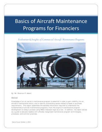
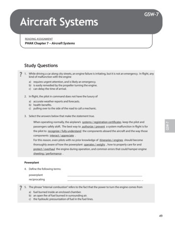
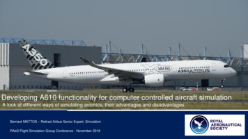
IFS ACADEMIC COURSE MANUAL5 Jan 2011are electrically operated. The switch is located on the instrument panel. The flap control circuit breaker can bemanually ‘tripped’ to disable the flap system.The DA20-C1 has a control stick for each pilot. The pilot can set the elevator trim with a control switch in the topof the control stick. Each pilot has a rudder pedal assembly. The assembly is attached to the cockpit floor. Thepilot can adjust the position of the rudder pedals with a T-grip selector on the rudder pedal assembly. The pilotmoves each primary control through a system of control rods and bellcranks. Cables operate the rudder. Anelectric actuator operates the flaps.TRIM SYSTEMThe DA20-C1 has an elevator with an electrically-operated trim system. Elevator forces are balanced using theelectric trim system. Control stick mounted trim switches control the elevator trim. The switches are positioned sothat they can be easily operated with the thumb. Forward movement of either switch gives nose down trimmingand aft movement of the switch gives nose up trim. An indicator shows the pilot the trim position. The trimswitches control electrical relays that supply electrical power to the electric pitch trim motor. An electric actuatormoves a spring system.If the switches are operated in opposing directions at the same time the trim motor will not operate. Operation ofthe trim switches in the same direction and at the same time will cause the trim motor to operate in that direction.A fixed trim tab attaches to the trailing edge of the left aileron and on the trailing edge of the rudder.FLAPSThe DA20-C1 has slotted flaps for landing and take-off. A three-positiontoggle switch controls the flaps. The switch is in the center section ofthe instrument panel. The flap position indicator has marks for CRUISE,T/O and LDG positions. The flaps are driven by an electric motor. Thecruise (fully retracted) and landing (fully extended) positions areequipped with position switches to prevent over-traveling. The electricflap actuator is protected by a circuit breaker (5 amp), located on theleft side of the instrument panel, which can be manually tripped todisable the system.The current flap position is indicated by three control lights beside the flap operating switch. When two lights areilluminated at the same time, the flaps are in-between positions.CRUISE green 0 T/O yellow 15 LDG yellow 45 AIRCRAFT FLIGHT INSTRUMENTSFlight instruments enable an aircraft to be operated with maximum performance and enhanced safety.Manufacturers provide the necessary flight instruments, but to use them effectively, pilots need to understand howthey operate.1. Magnetic Compass2. Vacuum Gauge3. Engine Tachometer4. Airspeed Indicator5. Attitude Indicator6. AltimeterA102-4
IFS ACADEMIC COURSE MANUAL7. CDI9. Heading Indicator5 Jan 20118. Turn Coordinator10. Vertical Speed Indicator12345678910PITOT-STATIC SYSTEMThe pitot-static system has these components: A combined pitot-static probe below the left wing An airspeed indicator (ASI) An altimeter A vertical speed indicator (VSI) A blind altitude encoder (Mode C)The pitot-static system supplies pitot pressure and static pressure to the air data instruments. A pitot-static probemounted below the left wing senses pitot and static pressure. Flexible hoses connect the pitot-static probe to theair data instruments.BLIND ALTITUDE ENCODERThe blind altitude encoder is located on the aft side of the firewall on the left. The encoder connects to the staticsystem. The encoder supplies these outputs: To the transponder for Mode C operation. To GPS system for altitude input.A102-5
IFS ACADEMIC COURSE MANUAL5 Jan 2011ATTITUDE AND DIRECTIONThe DA20-C1 has these attitude and direction indicators: Attitude Indicator (vacuum powered) Turn Coordinator (electrically powered) Stall warning horn Magnetic compass Heading Indicator (vacuum powered)VACUUM SYSTEMThe DA20-C1 vacuum system is powered by an engine-driven pump that is located on the front right side of theengine. The flow of air from this pump is used to power the Attitude Indicator and Heading Indicator. The pump isconnected directly to the driveshaft and operates any time the propeller is rotating. The system includes aVacuum Gauge that provides system pressure indications to the pilot. Air enters the vacuum system through afilter located between the firewall and the left side of the instrument panel. The vacuum necessary to operate thesystem is 4.5 - 5.2 in. Hg.ATTITUDE INDICATOR (AI)The attitude indicator uses a gyroscope as an attitude reference. The indicator showspitch and roll data. The display shows blue area for the sky and brown area for theground. A small bar shows the airplane’s wings. Horizontal markings above and belowthe horizon show pitch up and down. Each graduation is 5 . The roll display hasmarkings around the circumference of the instrument. The markings are at 10, 20, 30, 60and 90 degrees of roll.HEADING INDICATOR (HI)The HI is vacuum powered. The HI shows the direction of the airplane in relation to apreset heading. You set the heading by pushing and turning the knob on the face of theHI. The display has a 360 compass card with 5 graduations.A102-6
IFS ACADEMIC COURSE MANUAL5 Jan 2011TURN COORDINATORThe turn coordinator is an electrically-powered gyroscopic instrument. It operateswhen the main bus is powered and the turn coordinator circuit-breaker is closed. Awarning flag shows when there is no power to the unit. The warning flag goes out ofview when the turn coordinator has the correct power. The turn coordinator has a slipindicator. A ball in a curved tube filled with fluid shows when the airplane is slipping orskidding. When the ball is in the center, the turn is correctly coordinated. The turncoordinator shows the rate of rotation of the airplane about the vertical axis.MAGNETIC COMPASSThe magnetic compass aligns itself with the magnetic axis formed by the north/southmagnetic field of the earth. Fluid in the compass bowl gives dampens the swinging of thecompass card. Each graduation on the compass is 5 . A compass deviation card isattached to the compass. The compass light comes on when the DIM/BRIGHT switch isset to DIM.AIRSPEED LIMITATIONSAIRSPEED INDICATOR MARKINGSA102-7
IFS ACADEMIC COURSE MANUAL5 Jan 2011CABIN HEATThe cabin heat and defrost system directs ram air through the exhaust heat shroud into thecabin heat valve. The warm air is then directed to the window defrosting vents and to thecabin floor as selected by the Floor/Defrost lever. The cabin heat selector, located in thecenter console, is used to regulate the flow of heated air.The CABIN HEAT control lever moves the flap in the heat control valve. In the OFF position(fully forward) no hot air can flow into the cockpit. Move the lever aft (towards the ONposition) to let gradually more hot air flow into the cabin.The DEFROST/FLOOR control lever moves the flap in the distribution box. In theDEFROST position (fully forward) the hot air flows to the windscreen. Move the lever aft (towards the FLOORposition) to let the hot air flow to the floor.CABIN AIRThe cabin aeration is controlled by two adjustable air-vent nozzles that receive outside air from two fuselageNACA ducts. The two sliding windows in the canopy can be opened for additional ventilation. Ram air from theright side NACA duct also cools the equipment. Warm air escapes through holes in the instrument panel cover.OUTSIDE AIR TEMPERATURE (OAT)A102-8
IFS ACADEMIC COURSE MANUAL5 Jan 2011The OAT indicator is a digital instrument with a solid-state sensor. The sensor is located in the left side NACAduct.ELECTRIC CLOCKThe DA20-C1 has an accurate electronic clock (chronometer). The clock is at the topright of the instrument panel. The clock has a digital display panel. It has GMT, localtime and stopwatch functions. Two buttons control the clock.The INST LIGHTS circuit-breaker supplies power for the clock. When the airplanepower is off, an internal battery supplies the power for the clock. The internal batterycannot operate the display or control functions.HOURS METER (HOBBS METER)The engine-operated hours meter is at the bottom right of the instrument panel. It is anelectromechanical meter. The right side of the meter shows 1/10 of an hour. The other sideshows the hours. The airplane pitot-static pressure operates the meter.SEATS AND SAFETY BELTSThe seats are made of fiberglass and are non-adjustable. Each pilot’s seathas a four-point safety belt. The pilot can adjust the lap strap for correct fit.The shoulder straps are equipped with inertia reels which lock in the eventhigh G-forces are experienced, such as turbulence, a sudden stop, etc.Tighten the belts securely. The belt is opened by pulling the lock cover.RUDDER PEDAL ADJUSTMENTThe rudder pedals may only be adjusted on the ground. The pedals forrudder and brakes are unlocked by pulling the T-grip located in front of therudder pedal sledge tubes. Forward adjustment: Push both pedals forwardwith your feet while pulling lightly on the T-grip to disengage the latch.Backward adjustment: Pull pedals backward to desired position by pullingon T-grip.NOTE: After the T-grip is released, push the pedals forward with your feetuntil they lock in place.FLIGHT CONTROL LOCKA flight control lock is provided with each aircraft and should be installed whenever the aircraft is parked.NOTE: Failure to install the flight control lock whenever the aircraft is parked may result in control systemdamage, due to gusts or turbulence.Installation and Removal of the Control Lock:A102-9
IFS ACADEMIC COURSE MANUAL5 Jan 20111. Trim aircraft to neutral.2. Pull the left rudder pedals fully aft and check they are locked in position.3. Hook the Control Lock's forks over the rudder pedal tubes as shown above.4. Push down the Control Stick's leather boot to expose the Control Stick tube, and push the Control Stick forwardagainst the Control Lock.5. Loop the straps around the Control Stick as shown, and push forward on the Control Stick.6. Clip the straps into the left and right buckle receptacles located under the instrument panel.7. Adjust the straps as required. Straps should be tight to secure the controls properly.8. TO REMOVE, push the Control Stick forward (to relieve strap tension). Unclip the straps and remove theControl Lock. Store in the aircraft's baggage compartment.BAGGAGE COMPARTMENTThe baggage compartment is located behind the seat above the fuel tank. Baggage should be distributed evenlyin the baggage compartment. The baggage net must be secured.CAUTION: Ensure that baggage compartment limitations (44 lbs/20 kg max.) and aircraft weight and balancelimitations are not exceeded.CANOPYThe canopy is closed by pulling down on the forward handles on the canopy frame. Locking the canopy isaccomplished by moving the two locking handles on the left and right side of the frame.To close: Move both LH and RH locking handles forward.To open: Move both LH and RH locking handles backward.A canopy locking warning light, located in the upper center section of the instrument panel, indicates the status ofthe canopy’s locking mechanism. If the canopy locking warning light is illuminated, the canopy is not lockedproperly.CAUTION: Before starting the engine, the canopy must be closed and locked.NOTE: The Master Switch must be ON for the Canopy Locking Warning Light to be operational.LANDING GEAR SYSTEMThe landing gear system consists of the two main landing gear wheels mounted to aluminum spring struts and a60 castering nose wheel. The suspension of the nose wheel is provided by an elastomer spring. Flat sectionaluminum leaf-springs make the main gear struts.A102-10
IFS ACADEMIC COURSE MANUAL5 Jan 2011The nose gear is a tubular strut. A strong pivot attaches it to the forward fuselage. An elastomer spring pack(elastomer pack) attaches the strut to the engine mount. A pivot at the bottom of the strut has a trailing fork for thewheel. Nose and main gear have single wheels with low pressure tires, 26 psi nose, and 33 psi main.The landing gear absorbs vertical loads (for example, landing loads). Each main gear strut is a leaf spring whichdeflects upwards as the load increases. The elastomer pack in the nose gear compresses as the load increases.In each case, the spring returns to the original position when the load is removed.CAUTION: When placing the feet on the brake pedals, care should be taken to use only the toe of your shoe soyou do not contact the structure above the pedals, which could prevent effective application of the brake(s).BRAKE SYSTEMThe DA20-C1 has 2 separate brake systems. The pilot’s (left side) and co-pilot’s (right side) left rudder pedalsoperate the left system. It supplies pressure to the left brake caliper. The right rudder pedals operate the rightbrake caliper. Each system has a brake fluid reservoir. The reservoir attaches to the master cylinder on the copilot’s rudder pedal. The outlet from the master cylinder on the co-pilot’s rudder pedal connects to the inlet of themaster cylinder on the pilot’s rudder pedal. The outlet of the master cylinder on the pilot’s rudder pedals connectsto the parking brake valve. And the parking brake valve connects to the brake caliper.The parking brake valve is located below the right seat. It contains 2 valves which can seal the brake pressureinto the calipers. This keeps the brakes on. The pressure will reduce in time and the brakes will release. Aserviceable parking brake valve will hold the brakes on for more than one day.A102-11
IFS ACADEMIC COURSE MANUAL5 Jan 2011When you press on the brake pedal, these things happen: The connection to the reservoir is cut off by the initial movement. Further movement pushes fluid past the piston on the pilot’s master cylinder. The fluid flows through the parking brake valve to the right brake caliper The fluid pushes the piston and the pressure plate against the brake disk. The reaction force on the caliper pulls the back plate against the brake disk. And the right brake is applied.In the same way, when you press on the left brake pedal, the left brake is applied.Note: If one side of the system fails, one or both pilots can loose braking on that side.For example, a leak in the pipe between the co-pilot’s and pilot’s right master cylinders will cause a right brakefailure for the co-pilot. The pilot’s right brake will operate correctly. If the leak is between the pilots right mastercylinder and the right brake caliper, both pilots will have right brake failure.PARKING BRAKEThe Parking Brake knob is located on the center console in front of the throttle quadrant, and is pushed up whenthe brakes are to be released. To set the parking brake, pull the knob down to the stop. Repeated pushing of theA102-12
IFS ACADEMIC COURSE MANUAL5 Jan 2011toe-brake pedals will build up the required brake pressure, which will remain in effect until the parking brake isreleased. To release the parking brake, push on the toe-brake pedals before releasing the parking brake knob.Parking Brake OperationTo apply the parking brake: Press on both pedals. Pull the parking brake knob fully aft. Release your foot pressure on the pedals. If necessary, pump the brake pedals.To release the parking brake, select control to OFF.NOTE: When parking the aircraft for longer than 12 hours, place wheel chocks in front of and behind the mainlanding gear wheels. Tie down ropes should also be used if you are uncertain of favorable climatic conditions forthe duration of the park.POWERPLANTDA20-C1 aircraft are equipped with the Continental IO-240-B engine. The IO-240-B is a fuel injected, 4-cylinder,4-stroke engine with horizontally opposed, air cooled cylinders and heads. The propeller drive is direct from thecrankshaft. The propeller turns in a clockwise direction, when you look from the cockpit. Displacement: 239.8cu.in. (3.9 liters).A102-13
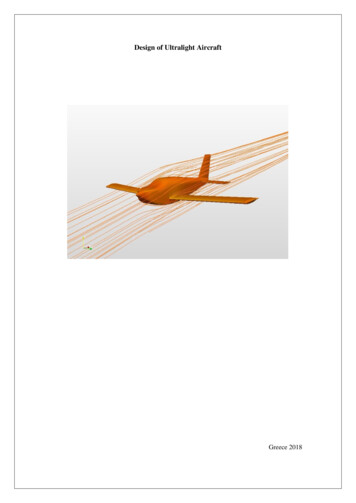
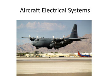
IFS ACADEMIC COURSE MANUAL5 Jan 2011Engine Operating Limitations:Max. Permissible RPM: 2800 RPMMax. Continuous Power: 125 HP / 93.25 kW at 2800 RPMCylinder Head Temperature (CHT):Maximum: 460 F (238 C)Minimum: 240 F (115 C) takeoff and descentFOUR-CYCLE ENGINE OPERATIONA102-14
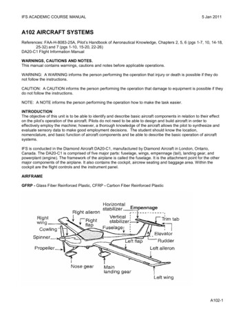
IFS ACADEMIC COURSE MANUAL5 Jan 2011The basic principle for reciprocating engines involves the conversion of chemical energy, in the form of fuel, intomechanical energy. This occurs within the cylinders of the engine through a process known as the four-strokeoperating cycle. These strokes are called intake, compression, power, and exhaust.1. The intake stroke begins as the piston starts itsdownward travel. When this happens, the intake valveopens and the fuel/air mixture is drawn into thecylinder.2. The compression stroke begins when the intakevalve closes and the piston starts moving back to thetop of the cylinder. This phase of the cycle is used toobtain a much greater power output from the fuel/airmixture once it is ignited.3. The power stroke begins when the fuel/air mixtureis ignited. This causes a tremendous pressureincrease in the cylinder, and forces the pistondownward away from the cylinder head, creating thepower that turns the crankshaft.4. The exhaust stroke is used to purge the cylinder ofburned gases. It begins when the exhaust valveopens and the piston starts to move toward the top ofthe cylinder.COWLINGThe powerplant has a top and a bottom enginecowling. The two halves attach to the airframe withcamlock fasteners. The top cowling has a left and a right air intake. The bottom cowling has one large air intake.AIR INTAKESThe GFRP air intake attaches below the front of the engine. Two flexible hoses from the air intake go to theexhaust muffler and the induction manifold.ENGINE DRAIN PIPESEach cylinder inlet port has a drain pipe. The drain pipe connects from the cylinder head to a “T” piece connector.From the “T” piece connector the drain pipes connect to a single pipe. The pipe has a check valve installed. Analuminum drain pipe attached to the mixture control valve gives drainage for the fuel pump.A102-15
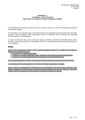
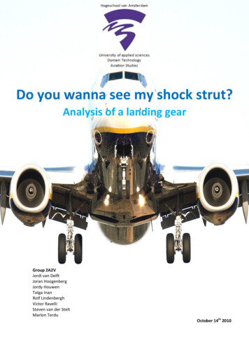
IFS ACADEMIC COURSE MANUAL5 Jan 2011ENGINE CONTROLSThe Mixture, Throttle and Alternate Air Control levers are grouped together in the center console. Thetension/friction for the controls can be adjusted using the friction knob located on the right side of the centerconsole.Mixture: right lever with red cylindrical handle and integral lock out lever. The mixture control lever features asafety lock which prevents inadvertent leaning of the mixture. To release, squeeze the safety lock lever and thecontrol knob together.Lever full forward Full RichLever full aft Idle CutoffThrottle: center lever with "T" handleLever full forward FULL throttleLever full aft IDLEAlternate Air: left lever with square handle. The alternate air control selects a second induction air intake in caseof restriction of the primary air intake (filter).A102-16
IFS ACADEMIC COURSE MANUAL5 Jan 2011Lever full forward Primary air intakeLever full aft Alternate air intakeMIXTURE CONTROL(a) CruiseThe mixture control allows leaning of the fuel mixture to maximize fuel economy duringcruise conditions. Teledyne Continental Motors specifies that above 75% of maximumrated power, the mixture must be set at FULL RICH. It should be noted that even withthe throttle set at the full power position, actual power may be less than 75% ofmaximum rated power and then leaning is required (reference Section 5.3.2, Cruiseperformance).(b) Reduced Throttle SettingsWhen operating at reduced throttle settings, other than steady state cruise, the mixtureshould always be set to FULL RICH. This applies to maneuvers (e.g.: stalls, spins, slowflight), descents, landing approaches, after landing and while taxiing. The onlyexception to this is for operating at very high altitudes, where the low air density mayrequire leaning to maintain satisfactory engine operation.(c) Full ThrottleWhen operating at full throttle, the mixture must be set at FULL RICH. This applies totake-off, balked landings and climb. The only exception is for operating below 75% ofmaximum rated power, as may be the case in an extended climb (reference Section5.3.2, Cruise performance).NOTE: All adjustment of the mixture control should be done in small increments.POWERPLANT INSTRUMENT MARKINGSA102-17
IFS ACADEMIC COURSE MANUAL5 Jan 2011OIL SYSTEMThe engine oil system performs several important functions, including: Lubrication of the engine’s moving parts. Cooling of the engine by reducing friction. Removing heat from the cylinders. Providing a seal between the cylinder walls and pistons. Carrying away contaminants.Reciprocating engines use either a wet-sump or dry-sump oil system. In a dry-sump system, the oil is contained ina separate tank, and circulated through the engine by pumps. In a wet-sump system, the oil is located in a sump,which is an integral part of the engine. The main component of a wet-sump system is the oil pump, which drawsoil from the sump and routes it to the engine. After the oil passes through the engine, it returns to the sump. Inthe DA20-C1 engine, additional lubrication is supplied by the rotating crankshaft which splashes oil onto portionsof the engine.The oil filler cap and dipstick (for measuring the oil quantity) are accessible through a panel in the engine cowling.If the quantity does not meet the manufacturer’s recommended operating levels, oil should be added. The AFM,POH, or placards near the access panel provide information about the correct oil type and weight, as well as theminimum and maximum oil quantity.The DA20-C1 engine has a high pressure, wet sump lubrication system. The oil is pumped by a mechanical,engine driven pump. An oil dipstick indicates the level of oil in the tank. The dipstick is marked for US quarts.Never operate the engine with the oil filler cap removed.Observe normal procedures and limitations while running the engine. With the engine stopped, check the oil levelon the dipstick. The oil level must be between the 6 US quarts and 4 US quarts level as indicated by the markingson the dip stick.The engine oil supply is contained in the engine sump. The engine oil pump supplies oil to the oil cooler adaptor(supplied by the airplane manufacturer). The oil cooler adaptor holds the oil filter. The oil filter is a full-flowcanister. The oil flows through the oil filter to a thermostatic relief-valve (Vernatherm). It also flows to the outlet ofthe oil cooler.The Vernatherm makes a by-pass between the
References: FAA-H-8083-25A, Pilot's Handbook of Aeronautical Knowledge, Chapters 2, 5, 6 (pgs 1-7, 10, 14-18, 25-32) and 7 (pgs 1-10, 15-20, 22-26) DA20-C1 Flight Information Manual WARNINGS, CAUTIONS AND NOTES. This manual contains warnings, cautions and notes before applicable operations. WARNING: A WARNING informs the person performing the operation that injury or death is possible if .