Transcription
Technical White PaperSoftware TechnologyImplementing ISO 26262 second editionwith the LDRA tool suite Cost effective software certificationfrom ASIL A to ASIL Dwww.ldra.com* Registration required to download the document LDRA Ltd. This document is property of LDRA Ltd. Its contents cannot be reproduced, disclosed or utilised without company approval.LDRA Ltd1Implementing ISO 26262 2nd edition with the LDRA tool suite
ContentsBackgroundAutomotive Safety Integrity Levels (ASILs)Changes to ISO 26262 second editionSecurity in the context of ISO 26262ISO 26262 Second Edition process objectivesAutomating ISO 26262 processesTechnical safety concept (part 4, clause 6)Specification of software safety requirements (part 6, clause 6)Software architectural design (part 6, clause 7)Reverse engineeringModel based developmentSoftware unit design and implementation (part 6, clause 8)Coding guidelinesSoftware architectural design and unit implementationSoftware unit verification (part 6, clause 9) and software integration and testing (part 6, clause 10)Structural coverage metricsSoftware test and model based developmentBidirectional traceability (parts 4 and 6)Confidence in the use of software tools (part 8)ConclusionsWorks CitedLDRA Ltd2334457788101010101214171920232425Implementing ISO 26262 2nd edition with the LDRA tool suite
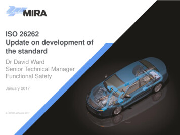
BackgroundThere is an ever-widening range of automotive electrical and/or electronic (E/E/PE) systems such asadaptive driver assistance systems, anti-lock braking systems, steering and airbags. Their increasing levelsof integration and connectivity provide almost as many challenges as their proliferation, with non-criticalsystems such as entertainment systems sharing the same communications infrastructure as steering,braking and control systems. The net result is a necessity for exacting functional safety developmentprocesses, from requirements specification, design, implementation, integration, verification, validation,and through to configuration.ISO 26262 “Road vehicles – Functional safety” was updated in 20181, having first been published in 20112in response to this explosion in automotive E/E/PE system complexity and the associated risks to publicsafety. Like the rail, medical device and process industries before it, the automotive sector based theirfunctional standard on the industry agnostic functional safety standard IEC 615083. The resulting ISO 26262 hasbecome the dominant automotive functional safety standard, and its requirements and processes arebecoming increasingly familiar throughout the industry.Many of the practices adopted by IEC 61508 and its derivatives can be traced to the commercial anddefence avionics industries. The RTCA Inc. series standards such as DO-178B/C4, DO-254, DO-278Aand their supplements, have proven that adherence to a structured set of best practices results in largescale reliable systems that protect public safety. Although ISO 26262 even in its original form was arelatively recent innovation, this history is significant because the establishment of functional safetystandards elsewhere gave rise to a sophisticated industry providing support for their effective application.Consequently, the automotive industry benefits from established and proven tools and techniquespredating ISO 26262 itself.This document describes the key software development and verification process activities of the standard,and uses LDRA’s tool suite to show how automation can assist in proving compliance in a cost-effectivemanner. Extracts from ISO 26262 second edition are shown in italics5.Automotive Safety Integrity Levels (ASILs)Like DO-178B/C and IEC 61508 before it, ISO 26262 specifies a number of hazard classifications levels – inthis case, known as ASILs (Automotive Safety Integrity Levels). Development process checks and safetymeasures are specified to avoid an unreasonable residual risk proportionate to the ASIL. ASILs range fromA to D, where ASIL D represents the most hazardous and hence demanding level so that the overheadinvolved in producing a safety critical ASIL D system (e.g. automatic braking) is significantly greater thanthat required to produce an ASIL A system with few safety implications (e.g. the in-car entertainmentsystem).ASILs are assigned as properties of each individual safety function at the item level, where an itemis defined as a “system or combination of systems, to which ISO 26262 is applied, that implements afunction or part of a function at the vehicle level”. The assigned ASIL for a safety function in a safetyrelated system is dictated by the properties of associated hazardous events, and is influenced by three ofits attributes: frequency of the situation (or “exposure”) impact of possible damage (or “severity”) controllabilityISO 26262 supports the decomposition of Functional Safety Requirements (FSRs) in a process often knownas “ASIL decomposition” (Figure 1), which can help to reduce cost and ps://www.iso.org/news/2012/01/Ref1499.html3IEC 61508:2010 Functional safety of electrical/electronic/programmable electronic safety-related systems4RTCA DO-178C Software Considerations in Airborne Systems and Equipment Certification, Prepared by SC-205, December 13, 20115Extracts from ISO 26262:2018, Copyright The British Standards Institution 2018. All rights acknowledged.2LDRA Ltd3Implementing ISO 26262 2nd edition with the LDRA tool suite
Figure 1: Decomposition of the different ASIL ratings throughout the item can occur over different systems,elements and componentsDecomposition of the different ASIL ratings throughout the item can occur over different systems,elements and components, working down through the systems, subsystems, software, and hardware. ASILdecomposition is typically performed manually and must result in redundant safety requirements allocatedto design elements of sufficient technical independence.Changes to ISO 26262 second editionThe 2018 revision to the ISO 26262 standard reflects industry feedback and updates based on advances intechnology since the standard was originally published. Reconstructed to provide more detailed objectivesand extensions to the overall vocabulary, notable additions to the standard include: objective oriented confirmation measuresmanagement of safety anomaliesreferences to cyber-securityupdated target values for hardware architecture metricsevaluation of hardware elementsadditional guidance on dependent failure analysisguidance on fault tolerance, safety-related special characteristics, and software toolsguidance for model-based development and software safety analysisIn addition, two completely new parts were added to the standard: ISO 26262 Part 11 which relates toSemiconductors6 and ISO 26262 Part 12 which relates to Motorcycles7.ISO 26262 second edition therefore consists of 12 parts with three focused on product development:system level (Part 4)8, hardware level (Part 5)9, and software level (Part 6)10. ISO 26262 Part 6 providesdetailed industry specific guidelines for the production of all software for automotive systems andequipment, whether it is safety critical or not.Security in the context of ISO 26262Most embedded software used in the automotive sector has not taken security requirements into account,simply because security and connectivity have not really been on the agenda. Automotive embeddedapplications have tended to be static, fixed function, device specific implementations. Isolation has been asufficient guarantee of security for many years, and practices and processes have relied on that status.Even as communication within the car became increasingly sophisticated, while ever the vehicle itselfremained an isolated entity, demonstrations of the ability to infiltrate safety critical systems from morebenign applications remained something of an academic point11. After all, it has always been possible todamage a car’s electrical systems with a pair of well-aimed wire cutters.6ISO 26262-11:2018 Road vehicles -- Functional safety – Part 11: Guidelines on application of ISO 26262 to semiconductorsISO 26262-12:2018 Road vehicles -- Functional safety – Part 12: Adaptation of ISO 26262 for motorcycles8ISO 26262-4:2018 Road vehicles -- Functional safety -- Part 4: Product development at the system level9ISO 26262-5:2018 Road vehicles -- Functional safety -- Part 5: Product development at the hardware level10ISO 26262-6:2018 Road vehicles -- Functional safety -- Part 6: Product development at the software 0.pdf -- Experimental Security Analysis of a Modern Automobile, Karl Koscher, Stephen Checkoway et.al.7LDRA Ltd4Implementing ISO 26262 2nd edition with the LDRA tool suite
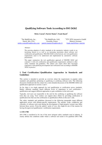
The key element is therefore the connection to the outside world. That changes things dramaticallybecause it makes remote access possible while requiring no physical modification to the car’s systems,most famously demonstrated in Miller and Valasek’s work “Remote Exploitation of an Unaltered PassengerVehicle”12.Perhaps because of this traditional isolation of automotive systems, ISO 26262 first edition made nospecific mention of security; indeed, in the field of safety critical embedded software, security concernshave generally been perceived to be a separate domain from the core business of functional safety. Yet ifhackers have the potential to remotely control steering, braking, and engine control systems, then securityvulnerabilities clearly put safety at risk. In this situation safety and security are indistinguishable.In acknowledgement of that fact, in ISO 26262 second edition channels of communication betweenfunctional safety and cybersecurity have been identified at both the functional safety managementlevel and product development at the system level. Such an approach provides a useful interface tothe recommendations outlined in the current SAE J3061 Cybersecurity Guidebook for Cyber-PhysicalVehicle Systems”13 “Cybersecurity” and the proposed ISO/SAE 21434 “Road vehicles – Cybersecurityengineering14”. ISO 26262-2:2018 Annex E “Guidance on potential interaction of functional safety withcybersecurity” further discusses “the possible interactions between the activities of functional safety andcybersecurity”.As for any other safety related risk, as soon as there is potential for security vulnerabilities to threatensafety, ISO 26262 demands safety goals and requirements to deal with them. It requires that the safetygoals be classified with appropriate ASILs for their criticality, designed with due reference to theirclassification, and developed and verified to show compliance with the system’s safety requirements. Inshort, the action to be taken to deal with each safety-threatening security issue needs to be proportionateto the risk (and hence ASIL).ISO 26262 second edition process objectivesA key element of part 4 is the practice of allocating technical safety requirements in the system designspecification, and developing that design further to derive an item integration and testing plan. It appliesto all aspects of the system including software, with the explicit subdivision of hardware and softwaredevelopment practices being dealt with further down the “V” model.Part 6 refers more specifically to the development of the software aspects of the product. It is concernedwith: general topics for the product development at the software levelspecification of software safety requirementssoftware architectural designsoftware unit design and implementationsoftware unit verificationsoftware integration and testingtesting of the embedded softwareFigure 2 is an extract from the standard, shown here with parts 4 and 6 highlighted for ing.pdf -- Remote Exploitation of an Unaltered Passenger Vehicle, Dr. Charlie Miller & Chris Valasek, August 12016j3061 -- Cybersecurity Guidebook For Cyber-Physical Vehicle Systems14https://www.iso.org/standard/70918.html -- Road Vehicles -- Cybersecurity engineering13LDRA Ltd5Implementing ISO 26262 2nd edition with the LDRA tool suite
Figure 2: Software development is primarily referenced in parts 4 and 6, shown here in the context of ISO26262 second edition as a whole.These different elements are not intended to be viewed as isolated silos; indeed, the standard insiststhat safety requirements are traceable to architectural design, that architectural design to unit designand implementation, and so on. ISO 26262 also requires that this traceability is bidirectional so that (forinstance) there are no safety requirements not covered in the architectural design, and no design elementsnot demanded by the architecture. This approach reduces the risk of failure by ensuring that not only is allrequired functionality present and proven, but also that there is no redundant code or “feature creep”.Once software safety requirements and architecture are defined, the software units can be designed andthen implemented in accordance with that design. The developing organization is required to establishcoding rules appropriate to the circumstances of the project, and the source code for the implementedunits must be validated to ensure that those coding rules are adhered to. The software units must thenbe dynamically tested (executed) to demonstrate that they fulfil the software unit design specificationand do not include unspecified functionality. Structural coverage analysis is then required to determinewhich code structures and component interfaces have not been exercised during execution of theserequirements-based test procedures. Unexecuted portions of code require further analysis resultingin addition or modifications of test cases, changes to inadequate requirements, removal of dead ordeactivated code, or unintended functionality.Variations in low level implementation details such as endianness and the sizes of data and addresswords can result in differing behaviour between test and target environments. Part 6 requires that the testenvironment shall correspond as closely as possible to the target environment.Although it provides extensive guidelines relating to the use of software tools, ISO 26262 does not requirethat they are used. However, for all but very trivial applications, attempting to meet the standard withoutsome level of automation would be a disproportionately labour intensive task. Tools are available toassist with almost all aspects of Part 6 not only to automate the tests themselves, but also to providedocumentary evidence (or “artefacts”) relating to their successful completion.LDRA Ltd6Implementing ISO 26262 2nd edition with the LDRA tool suite
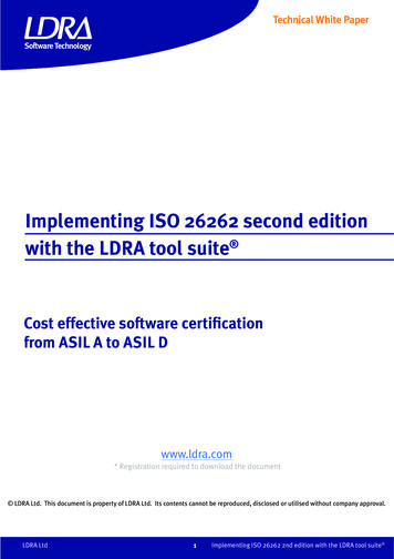
Automating ISO 26262 processesFigure 3 illustrates how each key stage in the ISO 26262 software development lifecycle can be automated.ISO 26262-4:2018section 7ISO 26262-4:2018section 6System anditem integrationand testingTechnical safetyconceptRequirementstraceabilityTBmanager IBM Rational DOORS ISO 26262-6:2018Polarion ALM,section 6ReqIF,Specification ofMS Word &software safetyExcelrequirementsModel baseddevelopmentIBM Rational Rhapsody Mathworks SimulinkEsterel SCADEISO 26262-6:2018section 11Testing of theembeddedsoftwareISO 26262-6:2018section 7ISO 26262-6:2018section 10SoftwarearchitecturaldesignStatic analysisQuality metricsCoding standards complianceTBvision LDRArules , LDRAcover Softwareintegration andverificationISO 26262-6:2018section 8ISO 26262-6:2018section 9Software unitdesign andimplementationSoftware unitverificationCompliancemanagementTest verificationTBvision andTBrun Integrated and modeldriven testingTBvision Automated unit testingTBrun LDRAunit TBeXtreme Programming standardschecking and metricationTBvision LDRArules 1Figure 3: Mapping the capabilities of an automated tool chain to the ISO 26262 second edition softwaredevelopment process guidelinesSoftware tools effectively leverage the experience and expertise of their vendors in this and otherindustries to ease the path to certification.Each element of the V diagram is expanded in the following clauses, and relevant tables from the ISO26262 second edition standard expanded and referenced. Note that each of the tables has a clearassociation with a particular element of the V-Model shown in Figure 3.Technical safety concept (part 4, clause 6)“The technical safety concept is an aggregation of the technical safety requirements and thecorresponding system architectural design, that provides rationale as to why the system architecturaldesign is suitable to fulfil safety requirements, resulting from activities described in ISO 26262-3 (withconsideration of non-safety requirements) and design constraints.”Although part 6 is the primary document for software development, it needs to be considered in thecontext of the system design for the product as a whole which is the domain of part 4. In order todevelop a system architectural design, functional safety requirements, technical safety requirements,and non-safety-related requirements are implemented. Clearly those work products include softwareconsiderations, but in this system design sub-phase, safety-related and non-safety-related requirementsare handled within one development process whether they impact software, hardware, or both in the formof the hardware-software interface.LDRA Ltd7Implementing ISO 26262 2nd edition with the LDRA tool suite
The products of this design phase potentially include CAD drawings, spreadsheets, textual documentsand many other artefacts, and clearly a variety of tools can be involved in their production. Themanagement of the status of each of those elements and maintaining traceability between them andsubsequent phases can cause a project management headache.The ideal tools for requirements management depends largely on the scale of the development. If thereare few developers in a local office, a simple spreadsheet or Microsoft Word document may suffice.Bigger projects, perhaps with contributors in geographically diverse locations, are likely to benefit froman Application Lifecycle Management (ALM) tool such as IBM Rational DOORS15, Siemens PLM PolarionALM16, or other ALM tools supporting standard Requirements Interchange Format17.Part 4 also requires adherence to the principle of bidirectional traceability. That requirement is commonto all phases of development, and its automation is discussed later in this document when other relatedprinciples have been introduced.Specification of software safety requirements (part 6, clause 6)The objectives of the software safety requirements sub-phase are concerned with: the specification or refinement of the software safety requirements the definition of safety-related functionalities and properties of the software required for theimplementation the refinement of the requirements of the hardware-software interface the verification that the software safety requirements and the hardware-software interfacerequirements are suitable for software development and are consistent with the technicalsafety concept and the system architectural design specificationThe technical safety requirements are refined and allocated to hardware and software during thetechnical concept phase as described in part 4, clause 8. The specification of the software safetyrequirements considers constraints of the hardware and the impact of these constraints on the software,but primarily focuses on the specification of software safety requirements to support the subsequentdesign phases.This sub-phase is essentially the interface between the product-wide system design of parts 4 and 6. Itdetails the process of evolution of lower level requirements as they relate specifically to the softwaresystem. That implies a continued leveraging of the requirements management tools selected for theproject, as discussed in relation to the System Design sub-phase.Software architectural design (part 6, clause 7)The objectives of the software architectural design sub-phase are concerned with: the development of a software architectural design that satisfies established requirementswith the required ASIL support for the implementation and verification of the softwareThere are many tools available for the generation of the software architectural design, with graphicalrepresentation of that design an increasingly popular approach. Appropriate tools include thoseexemplified by IBM Rational Rhapsody18, MathWorks Simulink19 and Esterel SCADE20. Figure 4 is amodified version of Table 4 reproduced from part 6, showing how the software architectural design is tobe verified both at design time and as the design is implemented as development -suite/ 16LDRA Ltd8Implementing ISO 26262 2nd edition with the LDRA tool suite
ASILTopicsABCD oo1aWalkthrough of the design1bInspection of the design 1cSimulation of the dynamic parts of the design 1dPrototype generationoo 1eFormal verificationoo 1fControl flow analysis 1gData flow analysis 1hScheduling analysis “ ” The method is highly recommended for this ASIL.“ ” The method is recommended for this ASIL.“o” The method has no recommendation for or against its usage for this ASIL.Satisfied by the LDRA tool suiteFigure 4: Mapping the capabilities of the LDRA tool suite to “Table 4:Methods for theverification of the software architectural design” specified by ISO 26262-6:201821Static analysis tools have a part to play in the verification of the design in the form of control anddata flow analysis of the code generated in accordance with it. As shown in Figure 5, the toolsderive the relationship between some or all of the code components and represent it graphicallysuch that it can then be compared with the intended design.Figure 5: Diagrammatic representations of control and data flow generated from source code by theLDRA tool suite aid verification of software architectural design21Based on table 4 from ISO 26262-6:2018, Copyright The British Standards Institution 2018. All rights acknowledgedLDRA Ltd9Implementing ISO 26262 2nd edition with the LDRA tool suite
Reverse engineeringMuch of the flow of the ISO 26262 processes is based on an overriding presumption that the projecteither begins with nothing, or is “proven in use”22 which implies the deployment of something that hasbeen shown to be reliable after many runtime hours. However, it is entirely possible that there is a needto adapt a long established application which would void that “proven in use” argument, as would theintegration of third-party source code into an existing design. What if source code exists, but designdocumentation doesn’t?The second edition acknowledges this dilemma with the addition of two new clauses in part 8, namelyclause 15 “Interfacing an application that is out of scope of ISO 26262” and clause 16 “Integration ofsafety-related systems not developed according to ISO 26262”.In such circumstances a graphical representation of the code (Figure 5) can help to establish thearchitecture of the existing system, such that the additions to it can be designed and proven inaccordance with ISO 26262 principles.Model based developmentThe LDRA tool suite can be integrated with several different model based development tools, one suchexample being MathWorks Simulink. The development phase itself involves the creation of the model inthe usual way, with the integration becoming more pertinent once source code has been auto generatedfrom that model.The integration itself is primarily leveraged during software unit testing, and software integration andtesting. The topic of model based development is therefore revisited later in this document in relation tothose sub-phases.Software unit design and implementation (part 6, clause 8)The objectives of the software unit design and implementation subphase are focused upon: the development of a software unit design in accordance with the established architecturaldesign, design criteria and requirements the implementation of those software units of evidence that software requirements are metCoding guidelinesThere are several aspects of software unit design and implementation to be considered, starting with adefinition of guidelines associated with how the selected programming language is to be used. Figure6 is a modified version of Table 1 reproduced from part 6. Table 1 in the standard shows the codingand modelling guidelines to be enforced during implementation, and it is superimposed here with anillustration of where the LDRA tool suite can confirm compliance, or can assist with the confirmation ofcompliance.22ISO 26262-8:2018 Road vehicles -- Functional safety -- Part 8: Supporting processesLDRA Ltd10Implementing ISO 26262 2nd edition with the LDRA tool suite
ASILTopics1aEnforcement of low complexity1bUse of language subsets1cEnforcement of strong typing1dUse of defensive implementation techniques1eUse of well-trusted design principles1fUse of unambiguous graphical representation1gUse of style guides1hUse of naming conventions1iConcurrency aspectsABCD “ ” The method is highly recommended for this ASIL.“ ” The method is recommended for this ASIL.“o” The method has no recommendation for or against its usage for this ASIL.SupportedSupported byby thethe LDRALDRA tooltool lsuitesuiteFigure 6: Mapping the capabilities of the LDRA tool suite to “Table 1: Topics to be covered by modellingand coding guidelines” specified by ISO 26262-6:201823All of these guidelines can be justified on the basis that they make the resulting code more reliable, lessprone to error, easier to test, and/or easier to maintain. For example: Low complexity (1a, Figure 6) is important because complex code is less easy to read and maintain,and hence more susceptible to error. For low complexity to be enforced, it needs to be quantifiedand a “pass/fail” criteria established.Language subsets (1b, Figure 6) such as MISRA C restrict the use of a programming language tothose elements known to be least susceptible to causing problems.Use of style guides (1g, Figure 6) ensures that the code has a consistent appearance no matterwho has written it. That makes it much easier to maintain or modify, which in turn makes it lessprone to error.The traditional approach to enforcing adherence to such guidelines would be to use peer code reviews.These may well still have a place in the development process – they can be very useful as an aid to learningbetween team members, for example – but automating the more tedious checks is far more efficient and lessprone to error (Figure 7).Figure 7: Highlighting violated coding rules and guidelines in the LDRA tool suite23Based on table 1 from ISO 26262-6:2018, Copyright The British Standards Institution 2018. All rights acknowledgedLDRA Ltd11Implementing ISO 26262 2nd edition with the LDRA tool suite
Part 6 highlights the MISRA language subsets, but onlyas an example – not as an instruction that they should beused. There are many different sets of coding rules available(see the sidebar), and even supposing a particular set ischosen as a basis it is entirely permissible to manipulate,adjust and add to it to make it more appropriate for aparticular application. Clearly, if a tool is to be useful in suchcircumstances then it too must be able to accommodatethese adjustments.Software architectural design and unitimplementationIf the coding guidelines of part 6 are analogous to the“bricks” of the software application, then its principlesfor software architectural design define where the “walls”should be built, and its unit implementation guidelinesdefine how those “walls” should be built.Establishing appropriate project guidelines for coding,architectural design and unit implementation are clearlythree discrete tasks but just like a bricklayer building awall, software developers responsible for implementing thedesign need to be mindful of them all concurrently. Figure 8and Figure 9 illustrate how the architectural design and unitimplementation principles required by part 6 can usuallybe checked by means of static analysis, just like codingguidelines.Language subsetsThere are many language subsets (or“coding standards”) each with differingattributes but nevertheless with strongsimilarities, especially when referencingthe same language. The most popularstandards include:CMISRA C:1998MISRA C:2004MISRA C:2012CERT CCWEC MISRA C :2008JSF AVHIC CERT C JavaCWECERT JFigure 8 is a modified version of Table 3 reproduced from part 6, and it is superimposed here with anillustration of where the LDRA tool suite can assist with the confirmation of compliance.ASILPrinciples1aAppropriate hierarchical structure1bRestricted size of software components1cRestricted size of interfaces1dStrong cohesion within each software componentABCD 1eLoose coupling between software components1fAppropriate scheduling properties1gRestricted use of interrupts1hAppropriate spatial isolation of the software components1iAppropriate management of shared resources “ ” The method is highly recommended for this ASIL.“ ” The method is recommended for this ASIL.“o” The method has no recommendation for or against its usage for this ASIL.Supported by the LDRA tool suiteFigure 8: Mapping the capabilities of the LDRA tool suite to “Table 3: Principles for software architectural design”specified by ISO 26262-6:201824As for the coding guidelines before them, all of these principles are foun
LDRA Ltd 4 Implementing ISO 26262 2nd edition with the LDRA tool suite 6ISO 26262-11:2018 Road vehicles -- Functional safety - Part 11: Guidelines on application of ISO 26262 to semiconductors 7 ISO 26262-12:2018 Road vehicles -- Functional safety - Part 12: Adaptation of ISO 26262 for motorcycles