Transcription
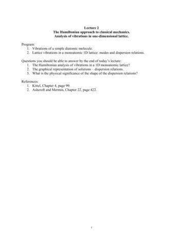
Transactions, SMiRT-22San Francisco, California, USA - August 18-23, 2013Division IMECHANICAL VIBRATIONS OF CANDU FEEDER PIPESUsama Abdelsalam1, Dk Vijay2, Hesham Mohammed3, Rick Pavlov4, Dan Neill51Tech. Expert, AMEC NSS Ltd, Power & Process Americas, Toronto, Ontario, Canada om)Section Manager, AMEC NSS Ltd, Power & Process Americas, Toronto, Ontario, Canada3Sr. Engineer, AMEC NSS Ltd, Power & Process Americas, Toronto, Ontario, Canada4Project Manager, Bruce Power Nuclear Maintenance Services Division, Tiverton, Ontario, Canada5Sr. Technical Officer, Components and Program Engineering, Bruce Power, Tiverton, Ontario, Canada2ABSTRACTThis paper presents a numerical dynamic analysis performed to estimate the maximum expectedchange in the mechanical vibrations of CANDU feeder pipes as a result of a change in flexural supportconditions. Finite Element Analysis models are constructed to represent 480 nuclear fuel channels alongwith their attached inlet and outlet feeder pipes. Each of the 480 models is excited using a random whitenoise forcing function and the corresponding peak vibration levels are recorded. Two cases are consideredto compare the vibration response with the designed support system (On-bearing) and without onesupport point (Off-bearing). Two types of excitations are considered; fflowlow induced feeder bend and endfitting excitations. The finite element results obtained from these two independent excitations are used tocalculate the ratio between the feeder vibration levels with and without the west inboard end-fittingjournal ring support. It is observed that the maximum increase in the expected feeders’ vibration peaklevels is 20% with the feeder bend excitation while only 2% increase is realized with the application ofthe end-fitting excitation. It is also observed that the average feeder dynamic peak response to the feederbends excitation did not significantly change considering the full feeders population. End-fittingexcitation results showed a reduction in the calculated average feeders vibration peak responses.INTRODUCTIONFuel channels (FC) on typical CANDU reactor are supported on the end-shield plates by journalrings to allow for axial creep elongation. A locking mechanism is used at either the east or the westreactor faces to control the axial position of the fuel channels. Figure 1 illustrates a typical fuel channeland feeders model showing the end-fittings, pressure tube, and attached feeders. Figure 1 also illustratesthe support points on the east and west end-fittings. In that particular diagram, the west end is axiallylocked using a welded stop collar allowing the fuel channel to elongate axially in the east direction. Toprevent east side Off-bearing condition, a fuel channel shift in the west direction may be used toreposition the fuel channel axially allowing for additional axial elongation. The west shift program leadsto a considerable fuel channel life extension as the axial elongation alternates between the east and westsides. Additional life extension may be obtained by going further allowing the in-board journal ring tolose contact on the west side and rely solely on the stop collar to provide the llateralateral support. In this paper,it is assumed that the west FC shift will cause a loss of the west journal ring lateral support. Thisconfiguration change may change the flexural vibration characteristics of the feeder pipes due to thechange in the west end-fitting support conditions. To address the effect of the support condition changeon the mechanical vibrations of the feeder pipes, a numerical analysis is performed to assess feeders’mechanical vibrations and compare the on and Off-bearing west scenarios.Park et. al (2007) presented a three dimensional model of a CANDU fuel channel and studied thefree and forced vibration responses under normal and assumed fault conditions. The flow-inducedvibrations as the cause of pressure tube excitation are reprerepresentedsented by a random transverse force with aunit amplitude. The results are compared with measured data which have been obtained from the reactornoise analyses by using stationary In Core Flux Detector (ICFD) noise signals. It is concluded that thevibration response spectra of a CANDU fuel channel can provide a useful means for detecting and
22nd Conference on Structural Mechanics in Reactor TechnologySan Francisco, California, USA - August 18-23, 2013Division Idiagnosing the abnormalities during plant operation. Dharmaraju and Rao (2008) presented a dynamicanalysis of coolant channel and its internals of Indian 540 MWe PHWR Reactor under simulatedloading/fault condition. Similar to Park (2007), the objective is to develop a diagnostics to monitor thehealth of the coolant channel over its operating life. The IAEA Nuclear Energy Series (2008) alsohighlighted the use of the ICFD noise signals in detecting and diagnosing the abnormalities in theintegrity of fuel channels. As the focus was the fuel channels only, feeders were not included in any of theaforementioned studies.Olson, David E. (2009) presented the “Pipe Vibration Testing and Analysis” chapter 37 in theCompanion Guide to the ASME Boiler & Pressure Vessel Code. This chapter deals with both steady stateand transient vibrations. The steady state vibrations are caused by flow turbulence and/or pressurepulsations (among other causes). These steady state vibrations may lead to fatigue failure and are thesubject of this paper. The ASME OM-S/G (2003) Operation and Maintenance of Nuclear Power Plantsaddresses the vibration requirements included in the piping Codes and USNRC Regulatory Guides. TheOM Part 3 standard addresses testing requirements and acceptance criteria for piping vibration. Thecriterion used for steady-state vibration is to limit the vibration stresses to a value below the endurancelimit of the piping material. The stress allowable in the OM guide is based on fatigue curves given inSection III of the ASME Code.CANDU feeders’ mechanical vibrations are customarily assessed using a velocity criterion thatmay be stated as follows:Vall VmaxWhere, Vall is the allowable feeder vibration velocity and Vmax is the expected maximum feeder vibrationvelocity. Both Vall and Vmax are affected by the change in support conditions. The analysis work coveredby this paper addresses the effects of the Off-bearing operation on the maximum expected feedervibration velocity, Vmax, (right hand side of the velocity criterion stated above). The velocity criterion forthe Off-bearing operation may be stated as follows:Vall,OFF Vall,ON *VRmaxWhere VRmax ( Vmax,OFF / Vmax,ON) is a conservative measure of the increase in the maximum feeders’vibration velocity considering the Off/On-bearing configurations. It is noted that the effect of the Offbearing operation on the allowable feeder vibration velocities (left hand side of the velocity criterion) willbe handled in a separate paper.Inlet/OutletFeederOutlet /InletFeederEastWestStop CollarWeld SupportGraylocHubInboard JournalRing SupportPTE/FE/FFigure 1: Schematic Fuel Channel/Feeder Model
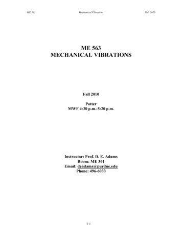
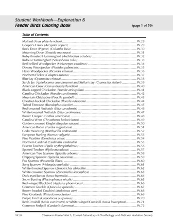
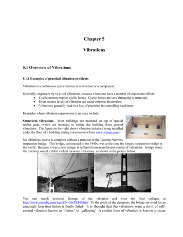
22nd Conference on Structural Mechanics in Reactor TechnologySan Francisco, California, USA - August 18-23, 2013Division IANALYSIS METHODOLOGYFinite element piping analysis models are constructed to represent all 480 fuel channels in atypical CANDU power reactor. Each model is a representation of the fuel channel and the connected inletand outlet feeders. Since the actual forcing function causing the feeder vibrations is currently unknown, awhite noise random function is used to excite the FC and Feeder models. Two independent forcingfunctions are considered in this analysis; end-fittings excitation and feeder bends excitation. The resultspresented in this paper are based on the following: A uniform maximum west shift displacement (relative to the design condition) is applied on all 480fuel channels. All fuel channels are assumed to operate Off-bearing on the west inboard journal ring support. The flow induced excitation remains the same for both On-bearing and Off-bearing operation sincethe flow path is not significantly changed. The analysis of the outlet feeders is performed using the projected end of life thicknesses whilenominal thickness values are used for the inlet feeders. Only the flexural modes of vibration are considered in this investigation. The fuel channel/feeder models are excited using a white noise random function and finite elementanalysis is performed to obtain the feeders’ power spectral density (PSD) response to this forcingfunction for the on- and Off-bearing configurations.FINITE ELEMENT MODELING & ANALYSISEach fuel channel and its attached inlet and outlet feeders is modeled using the ANSYS PIPE16linear elastic element with the appropriate flexibility factors and stress indices applied at bends/elbows.The wall thinning due to Flow Accelerated Corrosion (FAC) is uniformly modeled at the tight radiuselbow regions for each west and east side feeders. Figure 2 shows a typical FC/Feeder model in theoriginal design configuration. Figure 2 also shows the feeders anchor points at the headers along with thesupporting rigid and spring hangers. Figure 3a shows a close up view of the west end-fitting and a portionof the attached feeder in the design configuration (On-bearing) depicting the two support points at thestop collar and the inboard journal ring locations. Figure 3b shows a close up view of the east end-fittingand a portion of the attached feeder showing the inboard and outboard journal ring supports along withequivalent springs to account for bellows. Figure 4 shows a close up view of the west end-fitting withoutthe inboard journal ring support.Piping PropertiesThe different groups of piping components on each fuel channel/feeder model are distinguishedby applying specific set of real constants to the corresponding elements. Each real constant set defines thepipe outer diameter, thickness, stress intensification factors, flexibility factors, along with the heavy waterdensity.Material ModelA linear-elastic isotropic material model with the material properties listed in Table 1 is usedthroughout the analysis.Table 1: Linear Elastic Material PropertiesElastic Modulus,Poisson’s Ratio Density, lbf/in3psiFeeders29.1E60.30.2835Pressure Tube13.5E60.40.2366End Fitting29.1E60.30.2861Heavy Water--0.0395Feeders’ Boundary Conditions1. All feeders are fixed in all six degrees of freedom at the header anchor points.
22nd Conference on Structural Mechanics in Reactor TechnologySan Francisco, California, USA - August 18-23, 2013Division IRigid hangers and lower cantilever supports (if any) are represented by a vertical spring with 106lb/in spring constant.3. Spring hangers are modeled with ANSYS’ COMPIN14 element using the spring constants as per thedesign specifications.Fuel Channel Boundary ConditionsThe fuel channel is represented by three major components; east/west end-fittings and the pressure tubein-between.1. The west end-fitting is supported by equivalent stop collar stiffness values in all six degrees offreedom.2. The west end-fitting is constrained in the vertical and horizontal directions at the west in-boardjournal ring location in the case of On-bearing analysis. This support is removed in the case of Offbearing (West) analysis. The axial (Fuel Channel) direction is left free of constraints.3. The east end-fitting is supported at the in-board and out-board journal bearings locations in thevertical and horizontal directions. The fuel channel direction is left free of constraints.4. The east end-fitting is restrained in the rotational direction to reflect the effect of the bellows.5. The Garter springs separating the pressure and Calandria tubes are represented by horizontal andvertical springs with spring stiffness calculated from a closed form solution of a fixed-fixed beamrepresentation of the Calandria tube.2.Figure 2: Typical FC/Feeder Finite Element Piping Model
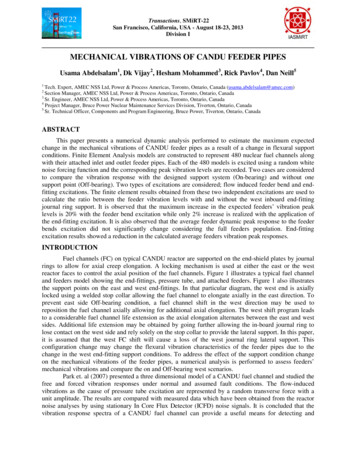
22nd Conference on Structural Mechanics in Reactor TechnologySan Francisco, California, USA - August 18-23, 2013Division IFigure 3a: Close up View of the West End-Fitting & Attached Feeder(On-Bearing Configuration)Figure 3b: Close up View of the East End-Fitting & Attached Feeder(On-Bearing Configuration)
22nd Conference on Structural Mechanics in Reactor TechnologySan Francisco, California, USA - August 18-23, 2013Division IFigure 4: Close up View of Design & Shifted West End-Fitting & Attached Feeder(Off-bearing Configuration)Analysis ProcedureEach of the 480 FC/Feeder models is analyzed for natural frequencies and mode shapes alongwith the corresponding stresses within the frequency range of 0-180 Hz. The modal analysis results arepost processed to calculate the allowable feeder vibration velocities for the west inlet and outlet feeders.The results of the modal analysis are also used to perform the power spectral density analysis using themodal superposition technique. The results of the PSD analysis are post processed to calculate the feedersvibration peak velocities.The analysis procedure is organized as follows:1. Perform modal analysis within the frequency range of interest (0-180Hz) to determine the naturalfrequencies, mode shapes, and corresponding stresses.2. Perform PSD FEA of the On-bearing models to obtain the vibration velocity response to the endfittings random excitation. Determine the maximum feeder-specific vibration velocity for the Onbearing configuration, Vmax,ON.3. Perform PSD FEA of the Off-bearing (West) models to obtain the vibration velocity response to theend fitting random excitation. Determine the maximum feeder-specific vibration velocity for the Offbearing (West) configuration, Vmax,OFFt.4. Determine the vibration velocity ratio for each individual feeder as follows:VRi Vmax,OFF / Vmax,ON5. Determine the global maximum vibration velocity ratio from the end-fitting excitation VR1,VR1 Max (VRi)6. Repeat for feeder bend excitations with the application of the bend forces instead to calculate VR2.7. Determine the global maximum feeder vibration velocity ratio,VRmax,OFF Max (VR1, VR2)
22nd Conference on Structural Mechanics in Reactor TechnologySan Francisco, California, USA - August 18-23, 2013Division IFEA Power Spectral Density Dynamic AnalysisTwo types of random excitations are considered; End-fitting and Feeder Bend. The magnitude ofthese forces is irrelevant to the analysis results considering that the analysis is linear and the targetoutcome is the ratio between the vibration response on and Off-bearing configurations.End-Fitting Excitation:The uniform feeder end-fitting excitation is considered as a representation of the flow inducedrandom vibrations as a result of the turbulence nature of the fluid flow in the fuel channel. A unit endfitting excitation is applied simultaneously in two planes on both the west and east end-fittings in thehorizontal (Z-X) and vertical (Y-Z) directions, respectively.Feeder Bend Excitation:The feeder bend excitation is introduced as a representation of the flow induced vibrations as theheavy water flows through the curved sections of the feeder pipes. The bend forces are applied at thebeginning and end of each individual bend in the tangent directions. In addition, forces are applied at thebeginning and end of reducers to account for the change in cross section area.FINITE ELEMENT ANALYSIS RESULTSThe results obtained from the modal and PSD analyses in ANSYS of all 480 west feeders are postprocessed in Microsoft Excel spreadsheets. The result of interest in this article is the peak vibrationvelocities on and Off-bearing. Figure 5 shows a comparison between the peak feeders’ vibrationvelocities Off-bearing against the On-bearing configuration. The vibration velocities are normalized usingthe maximum feeders’ peak velocity On-bearing. It is evident from Figure 5 that the end-fitting excitationproduces a decrease in the peak feeder vibration velocities when the in-board journal ring support on thewest side is not active. On the other hand, the feeder bend excitation shows both increase and decrease inthe peak feeder vibration velocities going from the On-bearing to the Off-bearing configuration. Sameobservations are valid whether the full feeder population (Figure 5), outlets only (Figure 6), or inlets only(Figure 7) are considered in the comparison.These observations are more evident when checking the histograms of the feeders peak vibrationvelocities as shown in Figure 8, Figure 9, and Figure 10 for the full population (outlets inlets), theoutlets only, and the inlets only, respectively. Figure 8 (a) shows the histogram of the feeders peakvibration velocities for the on and Off-bearing configurations under the end-fitting excitation. As can beobserved, the mean value of the peak vibration velocities is lower for the Off-bearing configuration.Figure 8 (b) shows the histogram of the feeders peak vibration velocities for the on and Off-bearingconfigurations under the feeder bend excitation. This figure indicates that the mean value of the peakfeeder vibration velocities is essentially unchanged whether it is from on or Off-bearing configurations.Figure (c) shows the histograms of the velocity ratio (Vmax,OFF/Vmax,ON) for all outlet and inlet feeders onand Off-bearing. As can be seen, the mean value is close to unity for the bend excitation case and themaximum is 1.20. Figure 9 and Figure 10 depict the histograms for the outlets and inlets only,respectively.Table 2 summarizes the statistics of the peak feeder vibration velocities for the whole population,outlets only, and inlets only. The table shows that the maximum increase in the feeders peak vibrationvelocity of 20% is obtained from the inlet feeders population. The maximum increase in the peakvibration velocity for outlets only is 13%.
22nd Conference on Structural Mechanics in Reactor TechnologySan Francisco, California, USA - August 18-23, 2013Division I1.21.2Bend Excitation110.80.8Normalized Vmax,OFFNormalized V max,OFFEnd-Fitting 2Normalized Vmax,ON0.40.60.811.2Normalized Vmax,ONFigure 5: Maximum Inlet & Outlet Feeders Vibration Velocity – OFF vs. On-bearing1.21.2End-Fitting ExcitationOutlets Only10.80.8Normalized Vmax,OFFNormalized V max,OFF1Bend ExcitationOutlets lized V max,ON0.40.60.811.211.2Normalized V max,ONFigure 6: Maximum Outlet Feeders Vibration Velocity – OFF vs. On-bearing1.21.2End-Fitting ExcitationInlets Only10.80.8Normalized V max,OFFNormalized Vmax,OFF1Bend ExcitationInlets Only0.60.40.20.60.40.20000.20.40.60.8Normalized V max,ON11.200.20.40.60.8Normalized Vmax,ONFigure 7: Maximum Inlet Feeders Vibration Velocity – OFF vs. On-bearing
22nd Conference on Structural Mechanics in Reactor TechnologySan Francisco, California, USA - August 18-23, 2013Division I100100100(a) EF Excitation(b) Bend Excitation80(c) Peak Velocity Ratio8080606060ONEF ExcitationONOFFBend 0.80.9100.10.20.3Normalized Vmax0.40.50.60.70.80.90.510.60.70.80.9Normalized Vmax11.11.21.31.41.51.41.51.41.5Vmax RatioFigure 8: Normalized Maximum Inlet & Outlet Feeders Vibration Velocity Histogram505050(a) EF Excitation(b) Bend Excitation40(c) Peak Velocity Ratio4040303030ONONEF ExcitationOFFOFFBend 0.9100.10.20.3Normalized Vmax0.40.50.60.70.80.90.510.60.70.80.9Normalized Vmax11.11.21.3Vmax RatioFigure 9: Normalized Maximum Outlet Feeders Vibration Velocity Histogram505050(b) Bend Excitation(a) EF Excitation40(c) Peak Velocity Ratio4040303030ONEF ExcitationONOFFBend 0.80.91Normalized Vmax00.10.20.30.40.50.6Normalized Vmax0.70.80.910.50.60.70.80.911.11.21.3Vmax RatioFigure 10: Normalized Maximum Inlet Feeders Vibration Velocity HistogramMinimumMaximumAverageTable 2: Statistics of the Feeders Peak Velocity Ratio (off/on)End Fitting ExcitationBend ts0.791.200.97SUMMARY & CONCLUSIONSAnalysis models are constructed to represent 480 CANDU reactor fuel channels along with theirattached inlet and outlet feeders. All 480 fuel channel/feeder models are dynamically excited withuniform random function covering a frequency range of 0-180Hz and the corresponding maximum feedervibration velocities are calculated for the on and Off-bearing conditions. Two types of excitations areconsidered; end-fitting excitation and feeder bends excitation. The analysis results indicated thefollowing:
22nd Conference on Structural Mechanics in Reactor TechnologySan Francisco, California, USA - August 18-23, 2013Division I With the end-fitting excitation, it is observed that the maximum expected feeder vibration velocitiesfor the Off-bearing condition are lower than that of the On-bearing condition.The feeder bends excitation, on the other hand, produces higher vibration response for the Offbearing condition. The maximum recorded increase is 20% observed for a very limited number offeeders. As a whole population, the average peak feeder vibration velocity is slightly lower for theOff-bearing condition compared to the On-bearing condition.The maximum expected feeder vibration velocities distributions for the on and Off-bearing operationare essentially the same for the whole population and for the outlets or inlets only.REFERENCESASME OM-S/G-2003 “Standards and Guides for Operation and Maintenance of Nuclear Power Plants”,January 31, 2004.ASME Boiler and Pressure Vessel Code, Section III, NB3600, 2007 Edition.Theory of Vibration with Applications, 2nd Edition, William T. Thomson, 1981.Dharmaraju, N. and Rao, Rama (2007). “Dynamic Analysis of Coolant Channel and its Internals of Indian540 MWe PHWR Reactor”, Science and Technology of Nuclear Installations, Volume 2008, ArticleID 764301.IAEA Nuclear Energy Series (2008). “On-line Monitoring for Improving Performance of Nuclear PowerPlants Part 2: Process and Component Condition Monitoring and Diagnostics”, No. NP-T-1.2.Olson, David E. (2009). “Pipe Vibration Testing and Analysis”, Chapter 37, Companion Guide to theASME Boiler & Pressure Vessel Code.Park, Jin-Ho, Yoon, Doo-Byung, Choi, Young-Chul, and An Chang-Gi (2007). “Analysis for theVibration Behavior of a CANDU Fuel Channel under Normal and Abnormal Support Conditions”,Paper # O-01/4, Transactions,, SMiRT 19, Toronto, August 2007.
on the mechanical vibrations of the mechanical vibrations and compare the Park et. al (2007) presented a three dimensional model of a CANDU fuel channel and studied the . Dharmaraju and Rao (2008) presented a dynamic analysis of coolant channel and its internals of Indian 540 MWe PHWR Reactor under simulated loading/fault condition. Similar .