Transcription
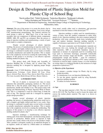
International Journal of Trend in Research and Development, Volume 3(3), ISSN: 2394-9333www.ijtrd.comDesign & Development of Plastic Injection Mold forPlastic Clip of School Bag1Harshvardhan Patil, 2Nikhil Deshpande, 3Sudarshan Bhambore, 4Kuldeepak Lokhande,5Aditya Kurlapkar and 6Pritam Patil, 1Assistant Professor, 2,3,4,5,6Students,1,2,3,4,5,6Department of Mechanical Engineering, Annasaheb Dange College of Engineering & Technology,Maharashtra, India.Abstract: The aim of the project is to create the plastic clip byusing CATIA V5 R20. The part modeling, Core-cavity design,CNC manufacturing programming. The material selection formold design is taken as Mild Steel. Cost of the total dieassembly and cost comparison of different plastic components(HDPE, ABS, PP, and PC) are estimated. Here the process isusing in injection molding and manufacturing a variety of partsfrom simple to complex components.Despite several advantages of plastic injectionmolding, the process of manufacturing an injection mold tool isstill a complex and highly skilled task that is very costly. Oncethe design is confirmed it usually takes several weeks or monthsto actually manufacture and market the product. This is mainlydue to the complexity involved in creating the mold tooling. Thepurpose of this project is to develop a cost effective injectionmolding method for plastic clip.This project deals with Design and Assembly ofInjection Molding Die of Plastic clip of school Bag. Theinjection molding die is designed by applying proper designprocedure.Keywords: Catia V5 R20 Modeling -Plastic Injection MoldingManufacturing Technique -Catia Models Of Cope, Drag,Spacer, Bottom Plate, Ejector Plate, Ejector Back Plate, EjectorPin-Catia Assembly Model,Design Of Gate, Runner-Defects.from metal, usually either steel or aluminium, and precisionmachined to form the features of the desired part.[2][4]Injection molding is widely used for manufacturing avariety of parts, from the smallest component to entire bodypanels of cars. Injection molding is the most common method ofproduction, with some commonly made items including bottlecaps and outdoor furniture. Injection molding typically iscapable of tolerances equivalent to an IT Grade of about 9–14.The most commonly used thermoplastic materials arepolystyrene (low cost, lacking the strength and longevity ofother materials), ABS or acrylonitrile butadiene styrene (aterpolymer or mixture of compounds used for everything fromLego parts to electronics housings), polyamide (chemicallyresistant, heat resistant, tough and flexible – used forcombs),polypropylene (tough and flexible – used for containers),polyethylene, and polyvinyl chloride or PVC (more common inextrusions as used for pipes, window frames, or as the insulationon wiring where it is rendered flexible by the inclusion of a highproportion of plasticiser).[9][14]A. Objective of the Experiment I. INTRODUCTIONThe use of plastic is increased now days in manyindustries like automobile, packaging, medical, etc. The reasonbehind this is that the plastic made things are quiet easier tomanufacture, handle and reliable to use. This project deals withDesign and Manufacturing of Plastic Injection Mold of PlasticClip. This is a component is used for school bags. It holds thestrip of bag. The injection mold die is designed by applyingproper design procedure.[1] To prepare a product design for Plastic clip by usingdesign procedure.To manufacture Low cost Injection Molding Die.To test the plastic injection mold by using Hydraulicinjection molding machine.To utilize for home business.II. DESIGNA. CopeThe top plate material is M.S. The size of top plate is150 X 150 X 20. The Top Plate is used to locate the runner andconvey the molten plastic material. The cope is as shown inpicture 2.1.Despite several advantages of plastic injectionmolding, the process of manufacturing aninjection mold tool isstill a complex and highly skilled task that is very costly. Oncethe design is confirmed it usually takes several weeks or monthsto actually manufacture andmarket the product. This is mainlydue to the complexity involved in creating the moldtooling. Thepurpose of this project is to develop a cost effective injectionmolding method for plastic clip.[3]Injection moldingis a manufacturing technique formaking parts from both thermoplastic and thermosetting plasticmaterials in production. Molten plastic is injected at highpressure into a mold, which is the inverse of the product's shape.After a product is designed, usually by an industrial designer oran engineer, molds are made by a Mold maker (or toolmaker)IJTRD May-Jun 2016Available Online@www.ijtrd.comPicture 2.1: CATIA Model of Cope291
International Journal of Trend in Research and Development, Volume 3(3), ISSN: 2394-9333www.ijtrd.comB. DragThe basic mold in this case consists of two plates. Intowhich one plate is the cavity which shapes the outside form ofthe mounting and is therefore known as cavity plate.bottom plate. The ejector plate is rest on theBottom Plate.Bottom plate is as shown in picture 2.4.The Die Plate material is M.S. The size of top plate is150 X 150 X 20. The Die Plate is used to locate the runner andconvey the molten plastic material. The actual product shape ismachined on die plate as shown in picture 2.2. Die plate hasejection holes as well as clamping holes.Picture 2.4: CATIA Model of Bottom PlateE. Ejector Top PlateThe Ejector Plate material is M.S. The size of Ejectorplate is 125 X 40 X 15. The ejector pins clamps on the ejectorplate. Ejector plate is as shown in picture 2.5. The ejector platemoves up stroke & down stroke.Picture 2.2: CATIA Model of DragC. SpacerSpacer is for maintaining the gap between bottom plate and coreback plate and also it helps in maintaining the required moldheight.The Spacer Plate material is M.S. The size of spacerplate is 150 X 20X 70. The spacer Plate is used to clamp thedrag plate & bottom plate. The ejection stroke is depend on theheight of spacer plate. Spacer plate is as shown in picture 2.3.Picture 2.5: CATIA Model of Ejector PlateF. Ejector Back PlateThe Ejector Plate material is M.S. The size of Ejectorplate is 125 X 40 X 15. The ejector pins clamps on the ejectorplate. Ejector back plate as shown in picture 2.6. The ejectorplate moves up stroke & down stroke.Picture 2.3. CATIA Model of SpacerD. Bottom PlateThe bottom plate houses the clamping screw the mainpurpose of bottom plate is to clamp the movable half of themold together i.e. core plate, core back plate, spacers and ejectorplate.The Bottom Plate material is M.S. The size of Bottomplate is 150 X 150 X 20. The whole assembly is mounted onIJTRD May-Jun 2016Available Online@www.ijtrd.comPicture 2.6: CATIA Model of Ejector Back Plate292
International Journal of Trend in Research and Development, Volume 3(3), ISSN: 2394-9333www.ijtrd.comG. Ejector PinThe Ejector Pin material is M.S. The size of Ejectorplate is Dia. 3 X 72. The ejector pins clamps on the ejectorplate. Ejector pin is as shown in picture 2.7. The ejector pinejects the sample up side.v. Plastic material that being used.vi. The cross sectional area of the runner must be sufficientto permit the melt to pass through and fill the impressionbefore the runner freeze and for packing pressure to beapplied for shrinkage compensation if required.Calculation of runner size:𝐷 W 0.5 𝐿0.253.7Where,D runner diameter.W weight of molding.L length of molding.[7][8]III. RESULT & DISCUSSIONA. Material SelectionMolds have been expensive to manufacturer. Theywere usually only used in mass production where thousands ofparts were being produced. Various types of materials formanufacturing a mold are as follows:1. Hardened Steel2. Pre-hardened Steel3. Aluminum4. Beryllium-Copper Alloy5. Mild SteelPicture 3.8: CATIA Model of Ejector PinH. AssemblyAfter assembly the Injection Molding Die of plasticclipis as shown in picture 2.8.[13]Conclusion:The first 4 materials are expensive as well as used formass production. And machining cost of this materials is alsohigh. For home business &Batch production we can use mildsteel because properties of all the materials are nearly same.B. Defects Occurred & Its Remedies1. Molding Flash:Picture 2.8: AssemblyMolding flash occurs when a thin layer of material is forced outof the mold cavity at the parting line or ejector pins location.This excess material remains attached to the molded article, andnormally has to be manually removed. The defect occurred isshown in picture 3.1.I. Design of GateThe size of the gate can be considered in terms of gatecross section area and gate length. The optimum size for gatewill depend on,i. Flow characteristics of the material to be molded.ii. The wall section of the molding.iii. The volume of material to be injected into impression.iv. The temperature of melt.v. Temperature of mold.[14]J. Design of RunnerWhen deciding the size of the runner following must beconsidered:i. The wall section and volume of molding.ii. Distance of the impression from the main runner.iii. Runner cooling type used.iv. The range of cutters available.IJTRD May-Jun 2016Available Online@www.ijtrd.comPicture 3.1: Mold Flash DefectCauses:1.Worn or poorly fitting cavity/mold plates including,mold plate deformations and obstructions (grease, dirt,debris)293
International Journal of Trend in Research and Development, Volume 3(3), ISSN: 2394-9333www.ijtrd.com2.3.4.5.Insufficient clamp force the machine clamp force mustbe greater than the pressure in the cavity (that is, clampopening force), to sufficiently hold the mold platesshut.Over-packing- Over-packed sections causes increasedlocalized pressure.Non-optimal molding conditions-Including materialviscosity, injection rate, and runner system. Forexample, high melt temperature, which makes a lessviscous melt.Improper venting-An improperly designed ventingsystem, a very poor venting system, or a ventingsystem that is too deep.IV. FINISHED PRODUCTThe finished product is used in the school bags to holdthe belts. The material of finished product is ABS (Acrylonitrilebutadiene styrene). The finished product is look like as shown inpicture 4.1 & 4.2.Remedies1.2.3.4.5.Ensure correctly fitting mold plates- Set up the mold toseal properly. Clean the machine from anyobstructions. Add pillar support or thicken the moldplates if there is any deformation of the mold plateduring the molding process.Avoid over-packingSelect machine with higher clamp forceVent appropriately-Use the material supplierrecommended venting size.Optimize processing conditions-Reduce pressures andshot size to the minimum required.Picture 4.1: Finished Sample (CATIA)2. Molding short shotA short shot is the incomplete filling of a mold cavitywhich results in the production of an incomplete part. If a partshort shots, the plastic does not fill the cavity. The flow freezesoff before all of the flow paths have filled.To ensure the finishedpart is of good quality, the part must also be adequately packedwith plastic.Causes1.2.3.4.Flow restrictions due to channels freezing orinadequate runner design.Hesitation and long or complex flow paths.Back pressure due to unvented air traps can cause ashort shotLow melt and/or mold temperature.Picture 4.2: Actual Finished SampleCONCLUSIONInjection molding has been a challenging process formany manufacturers and researchers to produce productsmeeting requirements at lowest cost. The presented work dealswith the design and development of injection mold tool of aplastic clip for school bag. CAD/CAE technology facilitates theuse of numerically controlled machining technology inmanufacturing of mold. In, turns this reduces number andcomplexity of manual setup operations.As can be seen from the above, the engineering andcreation of injection molds is a time consuming process. Thework is demanding in terms of knowledge, skills and exactingattention to details.Picture 3.2: Mold Short Shot DefectRemedies1.2.3.Eliminate air traps.Increase mold and melt temperature.Increase ram speed.[14]IJTRD May-Jun 2016Available Online@www.ijtrd.comThe designing was carried out with CATIA software.CATIA has been a real breakthrough in the industry bybecoming the primary source of communicating design. Due tothe use of the software the drawings need not be filed and storedin folder unlike in manual drafting and it is easily saved on thecomputer. 3D drawings are the best way to virtually represent astructure. Though one can manually create a 3D model itwouldn’t look as realistic as the 3D model generated by CATIA.While creating any drawing on paper, there is bound to be someamount of revision or modifications. In manual drafting we need294
International Journal of Trend in Research and Development, Volume 3(3), ISSN: 2394-9333www.ijtrd.comto erase and redraw to make any modification in the drawing butdue to CATIA this rework and time required for it is getreduced. Location of gates is quite difficult in family molds,using mold flow analysis best gate location is selected. Alsomold flow analysis is carried out to ascertain possible variationsin plastic flow and process variables.The Injection Molding Die of small plastic clip ofschool bag is most suitable for small size industries.Theproductivity is increased, manual labour required is less, theoperation is 0][11][12][13][14][15][16]Taylan Altan, Blaine Lilly, “Manufacturing of dies andmolds”, The Ohio State University, Columbus, USA,2010P. Krajnik, J. Kopac, “Modern machining of die andmold tools”, ELSEVIER, University of Ljubljana,Slovenia, 2004.Murlidhar Lakkanna, G.C. Mohankumar, “Design ofmoldsprue for injection molding thermoplstics”,ELSEVIER, NIT, Karnataka, 4th June 2015.MartonHuszar, “Sustainable injection molding: Theimpact of material selection and gate location on partwarpage and injection pressure”, ELSEVIER, Warpage,College of engineering, Swansea University, UK, 2015.C.L.Li, “Automatic layout design of plastic injectionmold cooling system”, The City University of HongKong, 2001.M.W.Fu, “The application of surface demoldability andmoldability to side-core design in die and mold”,ELSEVIER, Core, Hong Kong, 2008.Hsien-Chang Kuo, Ming-Chang Jeng, “The influence ofinjection molding on tribological characteristics of ultrahigh molecular weight polyethylene under dry slidingwear 268 (2010)”, 803-810.M.C.Song, “Research on effects of injection processparameters on the molding process for ultra-thin wallplastic parts journal of material processing technology”,2007, 668-671.T. Boronat, “Influence of temperature and shear rate onthe rheology and processability of reprocessed ABS ininjection molding process”, ELSEVIER, ABS, 2008.H.S.Wang, “Cost estimation of plastic injection moldingparts through integration of PSO & BP neural network”,ELSEVIER, 2004.All about plastic moulding. 2009. The History of sticmoulding.ca/history.htm#PlasticH. Kurtaran, T. ERZURUMLU, “Efficient warpageoptimization of thin shelled plastic part using responsesurface methodology and generic algorithm”, Adv.Manufacturing technology 27 (2006), 468-472.Manufacturer of Injection Molding Machine, Hikon,India, www.hikonindia.com/product-details.Design and manufacturing of plastic injection mold, 1-27The Rodon Group, Manufacturing Company based inU.S.A., info.rodongroup.com/blog/types.C. P. Natesha, K. Rameshbabu, “Design developmentand analysis of injection mold tool for divider housingmedian marker thermoplastic component”, 13th July2012.IJTRD May-Jun 2016Available Online@www.ijtrd.com295
using in injection molding and manufacturing a variety of parts from simple to complex components. Despite several advantages of plastic injection molding, the process of manufacturing an injection mold tool is still a complex and highly skilled task that is very costly. Once the design is confirmed it usually takes several weeks or months