Transcription
PC-DMIS Enterprise Metrology Solutions Dimensional integrity from design through manufacture
The Enterprise Metrology Solutions - EMSWhat if . . .Product designers could embed information about the critical dimensions of a part right into aCAD master model with little effort?A metrology software package could use CAD master models to do the “grunt work” of writinginspection programs?An inspection software package could automatically clean up after itself by optimizing probemovements?A single inspection package could control a diverse range of measurement devices, including: Traditional CMMs Vision Systems CNC Machine Tool Probes Portable Arms Laser TrackersMetrology software could make all dimensional inspection data and analysis readily availablein real time, both upstream and downstream of the manufacturing process?The answer to each of these questions and many more is with PC-DMIS Enterprise MetrologySolutions , you can.PC-DMIS Enterprise Metrology Solutions (EMS) enables companies of all sizes and industriesto integrate design, manufacturing and inspection operations into a single, seamless metrologysystem. PC-DMIS EMS makes it easy to collect and analyze dimensional data originatingfrom all manufacturing operations. With data quickly converted into meaningful, actionableinformation, corrective actions and process improvement can result. The benefits includesignificant time savings and reductions in scrap and rework costs.2
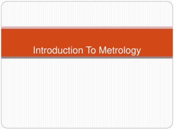
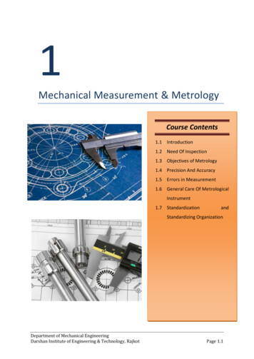
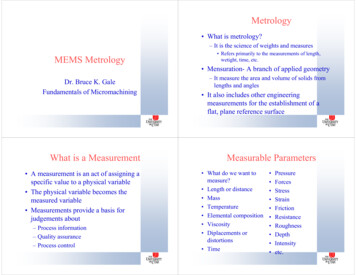
Born from CADThe PC-DMIS EMS product architecture is the result of more than twentyyears of ongoing development of the core PC-DMIS product, which wasoriginally conceived based on a simple conviction: if products werebeing designed in CAD, they should be inspected to CAD.Today, that philosophy has been extended to include solutions for allaspects of the dimensional measurement process. A look at the PC-DMISEMS model shows how PC-DMIS EMS uses a common architecture toprovide ways to design inspection systems able to produce a standardset of deliverables (usually information) regardless of the original sourceof the data.The key elements of the PC-DMIS EMS model are:Reference Data Set — The CAD model represents the theoretically“perfect” part.Collection Plan — PC-DMIS EMS uses a common set of tools to devisedata collection plans, regardless of the type of “collector” used (machineor sensor type). The tool set uses the reference data (the CAD model)to simplify the program design, and ensure consistency between theoriginal design intent and the inspection.Data Collection — When the collection plan is in operation,PC-DMIS EMS collects the actual data set from the device and storesit in a readily accessible form for both immediate and future use.Data Set Processing and Management — These are the back-endfunctions that PC-DMIS EMS uses to manage collected data setsaccording to the data collection plan.Functions — These are the analytical tools that PC-DMIS EMS usesto operate upon the nominal data. These functions include thecomparison of the collected data to CAD models, feature extraction,GD&T operations and data meshing.Deliverables — PC-DMIS EMS turns data sets into actionableinformation in a format most useful to the intended audience. Thisincludes inspection reports, data dashboards, SPC charts, reverseengineering data or a wide range of user-desired output.ArchitectureReference Data SetCollection PlanDataCollectionCAD FilePC-DMIS EMSData SetProcessing& sDataDashboardsSPC ChartsReverseEngineeringDataUser SpecifiedOutput3
Tools for Building Metrology Systems —Closing the Loop Between Manufacturing and DesignEnterprise Metrology Solutions for Process Control and ImprovementWith PC-DMIS EMS, a metrology information system can be tailored to meet the specific requirements of any manufacturer. The PCDMIS EMS product suite is an integrated group of metrology software products based upon a common technology, making it flexibleand powerful.With PC-DMIS EMS, manufacturers can build metrology capabilities into multiple stages of the production process from design throughmanufacture. This interaction at multiple stages of production improves information availability and allows data-driven decision makingthat can improve manufacturing operations.Ensuring Dimensional Integrity from Design Through ManufactureToday, design engineers do most of their work on 3D CAD systems where they design “perfect” parts. Manufacturing processes aredesigned that produce actual parts that are as close as possible to the perfect reference part. CAD-based PC-DMIS EMS softwareproducts provide the tools to monitor operations every step of the way. Areas where the PC-DMIS EMS system can be interfaced with aproduction process include:Product Design/CAD Database - Once a designer has stored a model in the CAD database, it becomes available to users of the PCDMIS EMS system for the development of inspection plans. PC-DMIS EMS with its optional Direct CAD Interfaces (DCIs) and Direct CADTranslators allows inspection departments to base their plans upon the most accurate versions of the CAD models.Quality Control Planning & Process Design - PC-DMIS Planner lets designers electronically annotate their drawings by definingfeatures, datums and dimensions. PC-DMIS can create inspection plans from the annotations for a variety of measurement devices.PC-DMIS Planner allows users to create synchronized bi-directional communications links between CAD files, inspection plans and partprograms, ensuring that parts are evaluated according to most up-to-date specifications.4
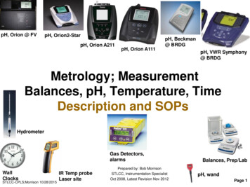
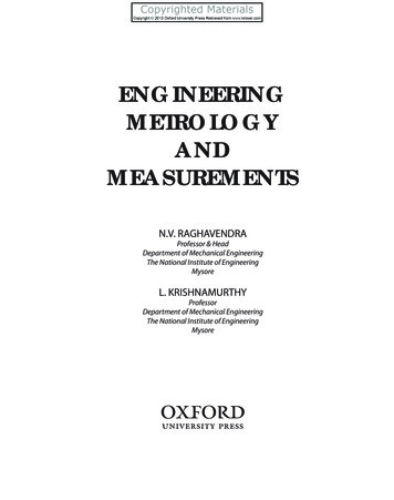
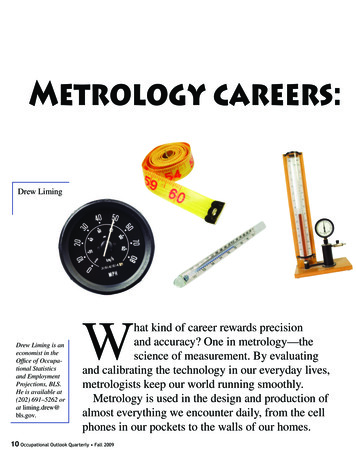
Enterprise Metrology SolutionsSPC-ErfassungManufacturingFeedback Schnittstelle ngProdukt-DesignNahezu inEchtzeitProduktionsstätMessen imten-Überprüfung Offline-BetriebPC-DMIS DCI/DCTGestaltung SData Collection and Reporting Loop – Each PC-DMIS moduleuses a standardized programming interface to create inspectionprograms. Programs run on a wide range of measurement devices.The inspection routines first tell the inspection program how toinspect a part and then how to analyze the generated data. Theresultant information goes to the PC-DMIS reporting engine. Thereporting engine, like the programming environment, is standardacross all versions of PC-DMIS. This means that no matter what thedata source, users can easily create and understand the reports andtake corrective actions quickly.The model shows three feedback loops of data collection to datareporting and the subsequent feedback to manufacturing. Eachconcentric loop gets a bit further away from the manufacturingprocess, indicating a greater amount of elapsed time is required forthe data collection and feedback-to-manufacturing cycle.Case 3: Collection to Feedback Cycle: Off-Line InspectionTraditionally, parts go to a Quality Lab or other off-line station for inspectionand this is still often the case. PC-DMIS CMM and PC-DMIS Vision arethe typical solution. While off-line inspection has the longest feedbackcycle, the advantages of accuracy or independence in the results are oftendesirable. The data aggregation function makes information from off-lineinspection’s reporting engines quickly available to those who need it.Data Aggregation – The flexible, powerful PC-DMIS reporting engineprovides in-depth information about individual parts. SPC applicationsallow analysis of the aggregated results from many parts. To meet thatneed, PC-DMIS EMS offers the PC-DMIS DataSuite group of SPC products.Analysis of data coming from any edition of PC-DMIS is combined real-timeinto live dashboards and reports of actionable information.Case 1: Collection to Feedback Cycle: Near-Real TimeWhen the time elapsed between the collection of inspection dataand the feedback of information to manufacturing needs to benearly instantaneous, PC-DMIS NC allows manufacturers to usemachine-mounted spindle probes to measure parts on the machineeither during or immediately following a machining cycle. Dataanalysis and real-time or near real-time feedback from the reportingengine to the production department is the deliverable.Case 2: Collection to Feedback Cycle: Shop Floor InspectionFrequently it is desirable or even essential to inspect parts at thepoint of production using portable measurement equipment.PC-DMIS Portable powers articulated arm CMMs, laser trackersand similar devices used on the shop floor for checking parts at thepoint of production. The reporting engine provides actionable dataimmediately to the operator or other production staff.5
PC-DMIS Environment —Scalable, Flexible Programming ToolsEnhancing Productivity and Quality Through Consistency,Scalability and FlexibilityPC-DMIS EMS provides manufacturers of all sizes with a tightly integrated suite of metrologysoftware products. Working seamlessly together, its modules present a consistent look andfeel across the full range of measurement operations including inspection planning, programdevelopment, part measurement, results analysis, report generation, and report distribution.CAD is KeyCAD has always been an integral part of PC-DMIS EMS. Using CAD: Designers embed their intent into CAD. Programmers develop their inspection routines using CAD. Measurement software compares results to CAD. Reports can include CAD for ease of interpretation.The icons shown below, and foreach PC-DMIS version in this brochure,indicate available features for that version.PROCADCAD Off-Line ProgrammingProgramming InterfaceReporting Interface Measurement results return to CAD for further reverse engineering andadditional evaluation.PC-DMIS EMS products offer a variety of links to CAD. Most include translatorsfor the major neutral CAD standards (IGES, STEP, etc.). For the most exactingapplications, Direct CAD Interfaces (DCIs) and Direct CAD Translators (DCTs)are available for all major CAD systems.A Direct CAD Interface (DCI) — Works directly on the native CAD model,accessed through the CAD database, without translation, and is the mostaccurate representation of the original model. Using DCI occupies a seat on theCAD system.A Direct CAD Translator (DCT) — Converts the CAD model directly from itsnative format into PC-DMIS format without using a neutral translation format forgreater accuracy. It does not occupy a seat on the CAD system.PC-DMIS EMS Measurement ProductsAll PC-DMIS measurement modules are based upon proven PC-DMIStechnology and share a common architecture. PC-DMIS EMS advantages:Direct CAD Interface Supports a wide range of measurement machine configurations anddevices types, from traditional CMMs to portable devices to machine tools.Direct CAD Translator All editions use a common programming interface and universalconventions. This flattens the learning curve and reduces training costs.Available as a RetrofitLinks to DataPage andWeb Reporter Programs can be shared among different machines and sensor typeswith minimal editing. Measurement data and information can be stored in a common database.This means that users can analyze their processes both over time andacross equipment types. A common reporting engine that allows for the sharing of reporttemplates among part programs and provides for the both the quickcustomization of existing reports and generation of new ones. A “Quick-Start” function lets users begin using their equipment withminimum delay. Direct connection to the PC-DMIS DataSuite SPC products for analysis ofaggregate results. A single set of NIST and PTB certified algorithms.6
Different Levels of Capability to Match Different RequirementsNot all manufacturers make the same types of parts, and not all parts have the samemeasurement requirements. To meet the varying requirements of a diverse customer base,PC-DMIS EMS offers three configurations of most of its measurement products.PRO meets the basic needs of companies that do not need to integrate CAD into theirmeasurement processes and do not need to measure contoured parts. PRO is ideal fornewcomers to part programming without CAD. It includes features aimed at streamliningthe process. These include “guess” modes for automatically identifying the type of featuresmeasured and “Quick Start” routines that automate many basic metrology functions. It alsooffers a rich set of programming, analytical and reporting tools.CAD is ideal for makers of prismatic parts that want to integrate CAD into their inspectionoperations. It expands upon the capabilities of PRO by letting customers program and inspectparts using all sorts of CAD models ranging from simple 2D “blueprints” through full 3D solidmodels. CAD allows full use of all PC-DMIS EMS CAD-linking technologies.CAD features an intuitive GUI and includes power “wizards” that guide engineers through theprogramming process. It includes a library of kinematic machine models for simulationand allows users to add new ones if required.CAD lets users measure the most complex parts. It includes all thecapabilities of CAD and adds the ability to measure intricate, contouredsurfaces including thin-walled sheet metal and plastic, blades, dies and molds.CAD supports numerous scanning devices and applications, and it includesalgorithms for managing copious amounts of data. Its links to CAD allow usersto compare measurement results directly against models for unsurpassedspeed and accuracy.CAD is feature rich, yet easy to use. Manyyears of experience developing metrologysoftware for varied applications in more than100 industries has refined PC-DMIS productssuch that programming tools to do even themost difficult jobs are available withoutburying the user in complexity.Enhancing ProductivityThrough Off-Line ProgrammingFor shops where machine time is a valuable commodity,PC-DMIS offers off-line licenses of the CAD and CAD configurations. Offline versions allow the inspectionmachines to be used primarily for measuring parts andnot for part programming. An offline license allows usersto develop, test and debug inspection routines off-lineusing CAD models. Simulated program execution ispossible on accurate kinematic models of their machines,so programs can be tested before they are ever used ona physical machine.7
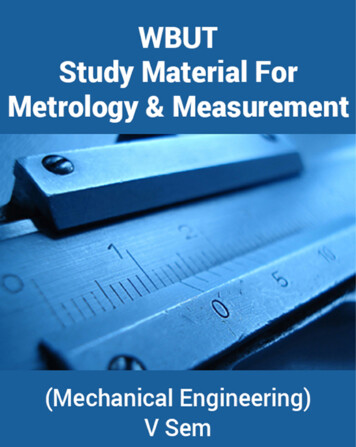
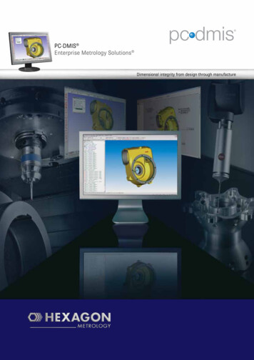
plannerEnterprise Metrology SolutionsLinking Design to InspectionPlanning for InspectionThe need for inspection is built into the manufacturing process. However, manyorganizations have discovered that the process of translating the design intent of a CADmodel into a set of inspection instructions for checking a real part isn’t built into anything.The process of communicating intent to inspection can be a difficult and time-consuminginformal process with numerous opportunities for misinterpretation and error. PC-DMISPlanner is the solution.PC-DMIS Planner software is a groundbreaking, stand-alone application that automates theflow of information between the virtual world of the design department and the real world ofthe engineering departments responsible for part manufacture and quality. PC-DMIS Plannercreates a bi-directional link between CAD models and their related inspection programs.Building Inspection Requirements into CAD ModelsThe communication of design requirements and modifications from thedesign department to the shop floor is often a haphazard proposition. It caninclude marked-up drawings, endless meetings, numerous phone calls andcostly errors. PC-DMIS Planner eliminates these problems by automatingthe communications process. Information flows electronically from designto quality assurance, keeping all departments in sync. PC-DMIS Plannereliminates one of the last significant disconnects in manufacturing.Plan and partprogram differencesSynchronizing Design and Inspection Using EnterpriseMetrology SolutionsChanging part specifications are inevitable. Ensuring that thelatest changes to the CAD model are incorporated into theinspection programs is the job of PC-DMIS Planner. Plannerdirectly links the design and inspection groups and trackschanges across the system, automatically notifying users ofany discrepancies and allowing changes to be made easily.8PlanadditionsCandidates fordeletion from thepart program
PC-DMIS Planner was specifically developedfor design engineers. Key advantages include: Elimination of marked-up drawings. All design intent (datums,dimensions, tolerances, etc.) is embedded in the CAD file tocreate inspection plans. Utilize CAD files translated from standard formats (i.e. IGES,STEP) or use the PC-DMIS Direct CAD Interface (DCI) orDirect CAD Translator (DCT) technologies to work on files inspecific CAD formats. Produce inspection plans that are independent of any inspectionequipment type and usable by any device running PC-DMIS. PC-DMIS can generate basic part programs automatically frominspection plans using default parameters that ensure consistentfeature measurement. Exploit PC-DMIS’s tools for optimizing probe paths and insertingclearance moves to produce efficient part programs.Tracking changesChanges to CAD models and inspection requirements are a constant inany manufacturing operation. Communicating these changes to the QAorganization is crucial to success. PC-DMIS and PC-DMIS Planner work jointlyto track changes in original CAD files and provide tools to keep the associatedinspection plans and part programs in sync. This process is automated, greatlyreducing errors.PC-DMIS and PC-DMIS Planner both incorporate change manager tools. Thechange manager tool in PC-DMIS Planner synchronizes CAD models andinspection plans. The change manager tool in PC-DMIS synchronizes inspectionplans and inspection programs.PC-DMIS Planner Change Manager: Compares an inspection plan to its CAD model andautomatically recognizes any differences between them. Highlights differences between models and plans and allowsthe users to make changes or ignore them.PC-DMIS Change Manager: Identifies differences between inspection plans and theirassociated part programs. Allows users to make changes based upon the differencesbetween plans and programs or ignore them. Works with PC-DMIS Planner Change Manager providingeasy-to-use tools for quickly updating part programs basedon changes to either the CAD file or inspection plan.Features that differbetween CAD and planCandidates fordeletion fromthe plan9
cmmThe Foundation of Enterprise MetrologyPC-DMIS CMM is the original product that forms the foundation of the PC-DMIS EMS solution. Theprogramming, evaluation and graphics engines form the platform that all other PC-DMIS softwareversions are built on, making it easy for customers to build an integrated enterprise metrology strategyon a common software platform. PC-DMIS CMM is available as standard equipment on all newHexagon Metrology brands of coordinate measurement machines. It is also easily installable asan upgrade on existing machines, including most non-Hexagon CMMs. PC-DMIS CMM offers fullysupported migration paths for many existing Hexagon Metrology legacy software products.Flexibility and Ease of UsePC-DMIS CMM is powerful and flexible, and also easy for both programmers and operators to use totheir best advantage. Users can: Make quick checks or program complex parts using a powerful, flexible graphical user interface. Configure and calibrate probes of all types quickly and accurately using a built-in set of probemanagement functions. Edit probe paths, add and delete hits, insert clearance moves and modify measurementparameters with the click of a mouse. Utilize graphical controls to modify part representations and set measurement parameters. Embed full screen pictures and videos into operator instructions. Measure complex, thin walled features quickly with a rich set of pre-defined routines. Develop tailor-made, high-level language routines and configure toolbars and menusaccording to specific needs and user preferences.Linking to CADPC-DMIS CMM was the first to integrate CAD in the measurement process.Ongoing development improves those links and helps synchronize theoperations of design, manufacturing and quality. CAD functions include: Manipulate CAD models by mirroring, adding layers, removing,hiding and changing entities and adding grids. Work with CAD models using either Direct CAD Interface (DCI) orDirect CAD Translator (DCT) technologies or using neutral formatslike IGES and STEP. Detect potential collisionsby combining CAD partmodels of parts with CADmodels of both holdingfixtures and machines. Automatically modify theCAD orientation to alignwith the probe direction. Import even the largestCAD files using a powerfulstate of the artgraphics engine.10Enterprise Metrology Solutions
Data AnalysisUsers of metrology software make important decisions based upon their measurement software andthe need to be confident that the results are repeatable and accurate. PC-DMIS CMM: Conforms to international (PTB and NIST) standards for CMM software. Supports GD&T according to ANSI Y14.5 2009 including: Bi-directional true position, polar coordinate method Maximum Material Boundary (MMB) and Least Material Boundary (LMB) of datums forprofile and true position Flatness per unit Unilateral and unequally disposed profile tolerances Processes the large clouds of points gathered by laser probes. Allows the analysis of results in 2D or 3D.Powerful Reporting ToolsThe purpose of measuring parts is to generate meaningful, actionable information.PC-DMIS CMM includes the universal set of full-featured reporting tools common to alleditions of PC-DMIS. Capabilities: Include CAD models in reports for easy interpretation. Graphical representations ofmeasured features can be used when CAD is not available. Generate inspection reports using either pre-defined templates or customized formats. Report results directly with PC-DMIS DataSuite products for SPC analysis and report distribution. Report measurement data to third party software packages for additionalanalysis and processing.Support for 3D ScanningImprovements in technology have made 3D scanning an important partof CMM measurement. PC-DMIS supports a wide range of devices anda full set of capabilities: Quickly define scan paths and extract nominal values and vectors. Scan and measure contoured and sheet metal parts using awide range of probes including touch trigger, analog and laser. Employ a wide variety of scanning methods and customizescanning techniques templates. Automatically scan and reverse engineer unknown surfacesand features. Use manual CMMs to scan both thin walled andcontoured parts.11
visionEnterprise Metrology SolutionsA New Take on Vision MetrologyBringing the Power of PC-DMIS to Vision MeasurementPC-DMIS has long set the standard for CAD-based CMM software. PC-DMIS Visionbrings these capabilities and a host of new ones to the world of vision measurement.PC-DMIS Vision provides vision metrologists with the same tools long available tousers of PC-DMIS CMM. These include powerful methods for measuring 3D partson vision systems. It also makes short work of measuring 2D parts, the traditionalapplications of vision measurement. In addition, PC-DMIS Vision users have accessto the complete PC-DMIS EMS range of additional analytical and reportingcapabilities.Putting CAD in Vision MeasurementPC-DMIS pioneered the incorporation of CAD into metrology software. PC-DMISVision adapts this fundamental capability to the unique demands of vision metrology.Allowing CAD models to be used as perfect “master parts” for programming andinspection purposes greatly improves both programming and inspection throughput.Benefits of PC-DMIS Vision’s CAD-based capabilities: Perform both part-to-CAD and advanced GD&T analyses not possible withtraditional vision software. Extract information right from the CAD model, eliminating errors of datainterpretation and input. Increase part programming throughput up to 75% by using 3D CAD models todevelop, check and edit inspection routines with point-and-click simplicity. Import CAD models and export measurement results in a wide range ofindustry standard and vendor specific formats. Develop programs off-line with an optional module that simulates allaspects of the measurement process. Switch between the CAD view and aCADCamera view (shown opposite, bottom) that accurately simulates notonly a camera image but also the illumination and magnification parameters. Draw on PC-DMIS’s feature based programming functions to simplify bothfeature creation and editing. Standard PC-DMIS reporting toolset allows CAD images to be embedded ininspection reports for ease of reference.12
Advanced Features for Vision MetrologyPC-DMIS Vision also includes a flexible and powerful toolset forcontrolling cameras, illumination and sensors on vision systems.Because the programming environment is identical to PC-DMIS CMM,anyone familiar with that version can easily make the transition tovision programming by learning the vision specific operations.PC-DMIS Vision features: Complete portability of part programs. Programs will run ondifferent vision machines or even other machine types such asCMMs with little or no modification. The revolutionary patent-pending Multi-Capture function(shown at right) automatically finds all features that fit withinthe field of view and simultaneously measures them, even ifthe features are of differing types. Multi-Capture then drivesthe camera to the next field of view, and repeats the process.For parts with dense clusters of features, this can makeinspection up to 70% faster. A Sensi-light function that assists users in selecting correctillumination settings. Feature based programming that not only simplifies thecreation of features but also the editing of features. Tools that automatically adjust critical measurementparameters like lighting and magnification. A Teach Mode Execute (TME) function that halts programexecution when a problem is encountered and lets usersreprogram features on the fly.Data AggregationPC-DMIS Vision and PC-DMIS EMS let you merge visionmeasurement data with other data taken fromanywhere within an organization into a consolidatedmetrology database, for analysis with measurementdata collected from multiple device types.13
portableEnterprise Metrology SolutionsBringing Metrology to the Shop FloorGetting the Most From Portable MeasurementPortable measurement devices have revolutionized the way manufacturers use metrology.Measurements tasks and analysis can take place on the shop floor where it has the most impact.Software that achieves optimal performance from portable measurement equipment is essential.PC-DMIS Portable is a highly sophisticated metrology software tightly integrated with portablemetrology tools such as portable measuring arms, laser trackers and total stations. Market leadingcapabilities deliver peak performance at the point of production.A Full Range of CapabilitiesWhether the task is inspection, building virtual assemblies or solving engineering problems, PC-DMISPortable gets the job done quickly and efficiently. Special user interfaces tailored for specific devicetypes arrange all the commonly used controls and functions for speed and ease of use.Integrating Portable Measurementinto Enterprise Metrology SolutionsPC-DMIS Portable is a part of the PC-DMIS Enterprise MetrologySolutions (EMS) suite of metrology software products. By running PCDMIS Portable on their portable measurement devices, companies of allsizes and industries can integrate their portable measurement operationsinto true metrology systems.14
PC-DMIS Portable: Minimizes the learning curve with a Quick Start GUI thatlets programmers and operators make full use of theirmachines’ most frequently used capabilities without beingoverwhelmed with detail. When needed, PC-DMIS’ fullcapabilities are only a couple of mouse clicks away. CAD capability allows inspection routines to reference theCAD during inspection or programming tasks. Automatic programming allows part programs to be createdduring a live inspection for recall and later use. Finds the correct nominal data automatically from CAD whilethe part is measured. There is no need to query the modelbefore measurement. Protects part programs from unauthorized changes with a“Protected Mode” that allows operators to run programs butnot modify them. Provides device specific user interfaces that organize thesoftware’s capabilities so that all controls for a particulardevice are readily available when the software is used onthat device. Guided inspection prompts users through measuringsequences with text, graphics and even movies. Promptsguide the user by indicating on the CAD model which featureto inspect next, increasing throughput and minimizing errors. Eliminates part-programming bottlenecks with off-lineprogramming. Using PC-DMIS Offline, programmers candevelop inspection sequences independent of the inspectiondevices. This reduces the time taken for inspection oradjustment on-site and minimizes any interruptionsto production. The full PC-DMIS set of reporting options are availableranging from simple text-based outputs to fully annotatedgraphical presentations based on a part’s CAD model. Features industry leading GD&T algorithms in supportof ISO and ANSI standards. PTB certified.15
ncEnterprise Metrology SolutionsOn-Machine,3-Dimensional MetrologyPC-DMIS NC brings the proven technologies of PC-DMIS, the world’s most advancedCMM software, to the work of on-machine part setup and validation. It is the first truemetrology software package for CNC probing systems. It lets machinists take full advantageof onboard CNC probes and allows manufacturers to make on-machine metrology anintegral part of their advanced manufacturing and quality assurance systems.With PC-DMIS NC, it is no longer necessary to struggle with the difficulties and
2 What if . . . Product designers could embed information about the critical dimensions of a part right into a CAD master model with little effort?