Transcription
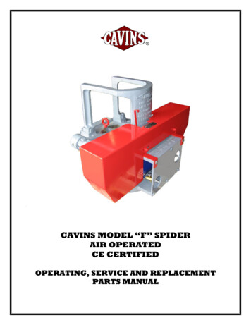
CAVINS MODEL “F” SPIDERAIR OPERATEDCE CERTIFIEDOPERATING, SERVICE AND REPLACEMENTPARTS MANUAL
CAVINS MODEL “F” SPIDERTABLE OF CONTENTSINTRODUCTION TO CAVINS SPIDERS. 3SPECIFICATIONS FOR CAVINS SPIDERS . 4MODEL “F” SPIDER ASSEMBLY AND ACCESSORIES. 5SLIPS FOR MODEL “F” SPIDER. 6INSTALLATION . 10OPERATION AND SAFETY PRECAUTIONS . 11MAINTENANCE & TROUBLESHOOTING. 13TROUBLESHOOTING. 23SHOP REPAIRS – ASSEMBLY WITH REPLACEMENT PARTS . 24REPLACEMENT PARTS. 27OVERALL DIMENSIONS . 30Cavins Oil Well Tools, 2853 Cherry Avenue, Signal Hill, CA 90755, U.S.A.Phone: 1 (562) 424-8564Fax: 1 (562) 595-6174Email: sales@cavins.comRevised 10/10/2009Page 2 of 30
CAVINS MODEL “F” SPIDERINTRODUCTION TO CAVINS SPIDERSThe “Advance” Spider developed by Cavins Oil Well Tools is considered to be the pioneer in powerslips. Through years of experience and testing, many improvements have been made, which makethe “Advance” Spider the leader in safe, economical and trouble free handling of tubular goods. Heattreated alloy steel is used throughout for the greatest possible strength and longest wearing life with aminimum of weight. The shafts are hardened alloy steel for longer life. Replaceable steel bushingsare fitted into the journal bearings. All bearings and journals are equipped with grease fittings forlubrication. Air cylinders and foot valves are mist lubricated through the air stream. All spiders areequipped with a manually operated safety latch, which should be used to positively lock the slips intheir set position. Because of the low operating pressure, the slips cannot release from the tubinguntil it has been raised by the elevators, thus, guarding against a lost string in the event that the footvalve is tripped accidentally. The slips, shafts and the air/hydraulic cylinders are protected by guardsto prevent damage caused by the elevators or other outside forces. Through research and fieldtesting, our engineers are constantly on the lookout for additional improvements which assure theuser in the field of receiving the safest and most maintenance free equipment available.A. APPLICATIONThe CAVINS “Advance” Spider is available in 5 models. The model “B” Spider is designed for usewith all API tubing sizes from 1.315” OD through 3-1/2” OD. The Model “C” and “C-HD” Spidersare designed for use with API tubing and drill pipe sizes from 1.315” OD through 5-1/2” OD. TheModel “F” Spider is capable of handling all API tubing, casing and drill pipe sizes from 2-3/8” ODthrough 8-5/8” OD. And finally, the Model “G” Spider can handle all API tubing, casing and drillpipe sizes from 2-3/8” OD through 13-3/8” OD. All models may be used on a rotary table with anadapter plate which fits into the master bushing drive square, thus centering the Spider on therotary table. All Spider Models can be modified to pass parallel strings of tubing or electric cable.B. COMPRESSED AIR OPERATED SPIDERAll Spider Models are available for compressed air operation. The relatively low operatingpressure required by the Spiders makes it easily adaptable to air supply on any rig or to aportable compressor if the rig is not so equipped.Each compressed air operated Spider requires the following equipment:1.2.3.4.5.One Air Spider Assembly complete.One Slip Assembly complete with inserts for each size tubing/casing/pipe to be run.One Air Filter, Pressure Regulator with gage and Lubricator assembly.One Foot operated Air control Valve assembly.Three lengths of Air Hose Assemblies. One hose to connect from the air supply to theinlet of the foot valve via the Lubricator assembly and the other two to connect the valveto the two ports on the air cylinder attached to the Spider.C. SLIPSA slip assembly consists of four individual segments, which are machined together as a unit toform a matched set. Each matched set must fit into a master gage which is identical to the bowl ina spider body, thereby assuring that all slip assemblies will fit in all spiders of the same model.However, slip segments from one set of slips will NOT interchange with slip segments fromanother set as they will not be matched sets. It is very important, that these sets are kept togetherto ensure proper gripping action. It is also important that adjacent segments within an assemblywhich are tied together with arm and tie bolts always be assembled together when replacing armbolts and tie bolts. A segment from one set of slips should never be substituted for a missingsegment in another set of slips.Revised 10/10/2009Page 3 of 30
CAVINS MODEL “F” SPIDERSPECIFICATIONS FOR CAVINS SPIDERSSPECIFICATIONSMODEL “B”MODEL “C”MODEL “CHD”MODEL “F”MODEL “G”MATERIALAlloy SteelAlloy SteelAlloy SteelAlloy SteelAlloy SteelWEIGHT – LESSSLIPS210 LBS95 KGS328 LBS149 KGS365 LBS165 KGS1175 LBS532 KGS2900 LBS1315 KGS28 IN/71 CM35 IN/89 CMA) 17 IN/43 CM totop of bowlw/o guard.B) 22-1/2 IN/57 CMTo highest ptw/o guard.A) 17 IN/43 CM totop of bowlw/o guard.B) 22-1/2 IN/57 CMTo highest ptw/o guardOVERALLHEIGHT15-1/2 IN39 CM16-1/2 IN42 CM16-1/2 IN42 CMBASEDIMENSIONS16 X 19-1/2 IN41 X 50 CM18-1/2 X 18-1/2 IN47 X 47 CM20 X 19 IN51 X 48 CM28 X 28 IN71 X 71 CM41 X 41-5/8 IN104 X 106 CMBOLT CENTERS11-1/8 – 16-1/2 IN28 – 42 CM12-3/4 – 14-1/2 IN32 – 37 CM12-3/4 – 14-1/2 IN32 – 37 CM18-3/4 – 24-1/2 IN48 – 62 CM31 – 37 IN78 – 94 CMGATE OPENING4-1/4 IN10.8 CM5-3/4 IN14.60 CM5-3/4 IN14.60 CM8.75 IN22.22 CM13-3/4 IN34.92 CMBOWL OPENING4-5/8 IN11.75 CM6-1/2 IN16.50 CM6-1/2 IN16.50 CM10-1/8 IN25.72 CM15-1/2 IN39.37 CMOPERATING AIRPRESSURE35 – 45 PSI40 – 50 PSI40 – 50 PSI60 – 80 PSI150 PSIOPERATINGHYDRAULICPRESSURE250-275 PSI1723 – 1896 KPA250-275 PSI1723 – 1896 KPA250-275 PSI1723 – 1896 KPA275-300 PSI1896 – 2068 KPA300-350 PSI2068 – 2413 KPATUBULARGOODS RANGE1.315 IN – 3-1/2 IN1.315 IN – 5-1/2 IN1.315 IN – 5-1/2 IN2-3/8 IN – 8-5/8 IN2-3/8 IN–13-3/8 INHOOK LOADCAPACITY110,000 LBS49.89 TONNES165,000 LBS74.84 TONNES250,000 LBS113.40 TONNES400,000 LBS181.44 TONNES700,000 LBS317.52 TONNESNOTES: To calculate maximum setting depth of string, divide the maximum load capacity by the weightper foot of the threaded and coupled tubular goods to be handled. For slips with Circular Button inserts and Strip inserts, reduce calculated setting depth by 40%.For slips with Chevron Inserts, reduce calculated setting depth by 25%.For slips with Integral teeth, no reduction of the calculated setting is necessary.For slips with Full circle inserts, no reduction of the calculated setting is necessary.For slips with Horizontal teeth inserts (applies to Model “F” Spider only), reduce calculated settingdepth by 25% for drill pipe only.Revised 10/10/2009Page 4 of 30
CAVINS MODEL “F” SPIDERMODEL “F” SPIDER ASSEMBLY AND ACCESSORIESPART 400TF170-P-20.500TF170-P-27.500TF170-SPART DESCRIPTIONNET WTLBS/KGSCAVINS 'ADVANCE' MODEL “F” AIR OPERATED SPIDER FOR2-3/8" TO 8-5/8" OD CSG FOR SINGLE STRING OPERATION(400,000# HOOK LOAD CAP.)FOOT OPER. RATCHET TYPE AIR CONTROL VALVE WITH QUICKCHANGE COUPLINGS & COVER GUARDCOMBINATION AIR CONTROL UNIT COMPLETE WITH RATCHETFOOT VALVE, AIR FILTER, PRESSURE REGULATOR, GAGE,LUBRICATOR & ALL FITTINGS MOUNTED IN SAFETY COVERGUARD.COMBINATION AIR CONTROL UNIT COMPLETE WITH PISTONFOOT VALVE, AIR FILTER, PRESSURE REGULATOR, GAGE,LUBRICATOR & ALL FITTINGS MTD. IN SAFETY COVER GUARD.FOOT OPERATED PISTON TYPE AIR CONTROL VALVE WITHQUICK CHANGE COUPLINGS & COVER GUARD.HAND OPERATED AIR CONTROL VALVEAIR HOSE ASSEMBLY-COMPLETE WITH Q/C COUPLINGS. ‘XX’REPRESENTS LENGTH OF HOSE DESIRED. 15 WOULD BE 15 FT.AIR FILTER/PRESSURE REGULATOR WITH GAGE & LUBRICATORUNIT COMPLETE WITH MOUNTING BRACKETPIN DRIVE ROTARY TABLE ADAPTER PLATE TO ADAPT MODEL "F"SPIDER TO API 20-1/2" PIN DRIVE MASTER BUSHING.PIN DRIVE ROTARY TABLE ADAPTER PLATE TO ADAPT MODEL "F"SPIDER TO API 27-1/2" OR 37-1/2" PIN DRIVE MASTER BUSHING.ROTARY TABLE ADAPTER PLATE TO ADAPT MODEL "F" SPIDERTO ANY ROTARY TABLE SQUARE DRIVE MASTER BUSHING WITHA STANDARD A.P.I. 13-9/16" ID.Revised 10/10/2009Page 5 of 5200/90.7185/83.9120/54.4
CAVINS MODEL “F” SPIDERSLIPS FOR MODEL “F” SPIDERMASTERSLIP BODYFOR MAX ODPIPE3-1/2”4-1/2”5-1/2”7-5/8”API 7-5/8”8-5/8”Revised 10/10/20098-5/8”TYPE “TD” SLIPS COMPLETE WITH INSERTSNETWT.PART .000TF150-D-7.625TF150-R-8.625INTEGRAL TEETH NO INSERTS REQDPage 6 of 154/70200/91205/93192/87143/65NO. OFTYPE“HTI”INSERTSPER SET161616323232323232484848-
CAVINS MODEL “F” SPIDERMASTERSLIP BODYFOR MAX ODPIPE3-1/2”4-1/2”5-1/2”7-5/8”TYPE “TD” SLIPS LESS INSERTSAPI PIPESIZESITACCOMODATESOD2-3/8” TO 3-1/2”3-1/2” TO 4-1/2”4-1/2” TO 5-1/2”6-5/8” TO 7-5/8”PART -D-7.625SLIP SIZESFOR MASTERTO HANDLESLIP BODYTUBULARSIZEGOODS 2”5-1/2”7-5/8”Revised 10/10/2009135/61108/49141/64174/79NO. OFTYPE“HTI”INSERTSPER SET16323248NO. OF TYPE “HTI” INSERTS PER SETPER SETODNO REQDPART -7.625SLIP SIZESFOR MASTERTO HANDLESLIP BODYTUBULARSIZEGOODS SIZEODNETWT.LBS/KGSNET 19.5/8.812.5/5.726/11.831/1418/8INSERTS – TYPE “HTI” FOR “TD” SLIPSEACHODPART 625X7.000TF157-7.625Page 7 of 30NET 9.88/.39.61/.28.39/.18.54/.24.65/.29.37/.17
CAVINS MODEL “F” SPIDERMASTERSLIP BODYFOR MAX vised 10/10/2009TYPE “FCR” SLIPS COMPLETE WITH INSERTSNETWT.PART TF610-FCR-7.625Page 8 of 01220/100209/95199/90186/84NO. OF“FCI”INSERTSPER SET44444444444444444444
CAVINS MODEL “F” SPIDERMASTERSLIP BODYFOR MAX ESOD2-3/8” TO 3-1/2”3-3/4” TO 5-1/2”5-3/4” TO 7-5/8”TYPE “FCR” SLIPS LESS INSERTS WITH RET PINSNETWT.PART CR-7.625116/53115/53133/60NO. OFTYPE“FCI”INSERTSPER SET444Note: * A set of cotter pins is supplied with each set of the “FCI” inserts.Some FCI inserts may require a minimum order of 2 sets.* INSERTS – TYPE “FCI” FOR TYPE “FCR” SLIPS FOR SINGLESTRINGSSLIP SIZESFOR MASTERSLIP BODYSIZETO HANDLETUBULARGOODS SIZEODODNO REQDPART 5-1/2”7-5/8”PER SETSLIP ASSEMBLY HARDWARE/SPARE PARTSNO PER SETPART NUMBERDESCRIPTIONREQDARM BOLT2TF154NUT FOR ARM BOLT2TF155TIE BOLT FOR SLIP2TF152LOCK NUT FOR TIE BOLT2TB112RETAINING PIN4TF601COTTER PIN *4TC602-SBOLT (3-1/2” TD SLIPS)4TF156-LBOLT (4-1/2–7-5/8 TD SLIPS)8 OR 12TF156-SLOCK NUT4,8 OR 12TF158Revised 10/10/2009Page 9 of 30NET 466/3053/24NET 1
CAVINS MODEL “F” SPIDERINSTALLATION The spider can be installed directly over the wellhead utilizing the slots in the base or on arotary table using an adapter plate. Adapter plates are available for both API square and pindrives.The proper size slips along with inserts can then be installed on the spider with the bolts andnuts provided. It should be verified that the slip set used is a matched set and the insertsinstalled are a combination of left and right segments if using type “FCR” slip body.Air hoses fitted with quick disconnects allow the cylinder on the spider to be connected to theair control valve assembly (refer to figure below). Before connecting the quick disconnects,they should be inspected for any debris and cleaned. The air control valve assembly isconnected to the air supply via a pressure regulator, lubricator and filter combination unit. Theair supply can be either the rig air supply or a portable compressor unit.Revised 10/10/2009Page 10 of 30
CAVINS MODEL “F” SPIDEROPERATION AND SAFETY PRECAUTIONS Read and understand all operating and service instructions before usingthe Spider Assembly. All operating personnel should be thoroughly trainedand knowledgeable of the equipment operation and safe use. Never place hand or feet in or around the operating parts of the SpiderAssembly when in use. Always lower the Slips into the bowl and disconnect the power sourcebefore moving, installing or performing maintenance on the equipment.The air supply to the cylinder is between 60 to 80 psi and hydraulic fluid issupplied at between 275 and 300psi to a hydraulic cylinder. Spider furnished with pinch point guards should not be used without theguard properly installed. Safety latch should be checked for proper function on a daily basis andreplaced when broken or damaged. Never use the equipment without asafety latch installed. The Spider assembly should only be lifted or hoisted by the body guardproperly secured to the spider body. Never lift or hoist the equipment byattaching to any moveable component, the cylinder guard or the pinchpoint guard. Never use the Spider without the gate and gate bolt installed. Gate shouldonly be removed using the lifting eye provided. Do not overload the Spider – never exceed the rated capacity.The following steps need to be taken before changing out slips or replacing inserts when the spider ispositioned over the well bore: Cycle the foot control valve or other designated rig console control valve until the slips and theslip lifting arms are in the fully open/retracted position. Engage the safety latch to prevent the liftarms from closing and disconnect the hoses to the operating cylinder to prevent accidentaloperation of the spider. Remove and install another set of slips or replace inserts in the slip segments already installed.Please reference maintenance and troubleshooting section drawings for slip and insertinformation. Rig personnel should take precautions during this activity to avoid dropping parts andtools down the hole.Revised 10/10/2009Page 11 of 30
CAVINS MODEL “F” SPIDER The slip sets consist of four segments and each segment is marked to ensure a matched set isinstalled in the spider. Two segments bolted together makes up one half of a set and is installedon the lift arm by running a bolt through the outside hole on the lugs of the slip segments and theslot in the lifting arm and installing the lock nut. Stroke the slips and check to make sure that theindividual slip segments do not bind.Insert Replacement procedure for Cavins Full Circle (Type “FCR”) Slips with replaceable “FCI”inserts: Place the Safety Latch in the locked position and remove the Slips from the Spider body byremoving the Lifting Arm Bolts and NutsRemove the Cotter Pins from each Slip segmentRemove the Insert Retaining Pins (insert a dowel rod or punch from the lower end of the slip andtap them out if necessary)Remove the old “FCI” Inserts from each Slip segment (gently tap them out with a hammer ifnecessary)Clean and lubricate the slips as needed prior to installing the new “FCI” Inserts and check forexcessive wearEach set of (4) “FCI” Inserts comes with 2 right and 2 left hand segments. Install the new “FCI”Inserts in each slip segment and check the fit. Inserts should fit snugly. If the fit appears to betoo loose, then the Slips may need to be replaced.Re-Install the Insert Retaining Pins in each Slip Segment.Re-Install the new Cotter Pins (included with the “FCI” Insert set) in each Slip Segment.Make sure the Safety Latch is in the locked position and Re-Install the Slips in the Spider Body bysecuring them to the Lifting Arms with the proper Slip Bolt and Self-locking NutOperational performance of the spider should be continuously monitored while in use. Check the function of the slips, and if necessary, adjust the cylinder pressure to control the rate ofspeed for raising and lowering the slips in the spider bowl. This may also require adjustment ofthe travel stop screw and or the cylinder yoke if changing out to a different slip size. This mayalso require adjustment of the cylinder pressure to compensate for the different weight of the newslip installed.Make appropriate adjustments to ensure that the slips will not damage the pipe or the inserts bysetting too hard (slamming down) on the pipe. Always remember to load the hook or top drivebefore opening the slips and to fully open on the slips before allowing pipe travel to preventdamage to pipe as well as inserts.Revised 10/10/2009Page 12 of 30
CAVINS MODEL “F” SPIDERMAINTENANCE & TROUBLESHOOTINGThe Cavins F spider design has been proven to be a safe, durable and trouble free design for bothmanual and power operated slips. Since the F spider and slip sets were first introduced in 1962, the toolhas been used routinely for drilling, completions, well servicing and snubbing operations around theworld. The 200 ton rating of the F spider and the capability of running tubulars from 2 3/8 to 8 5/8diameters makes it a versatile tool and when properly used and maintained, will provide years of troublefree service.Cavins F spiders and slip segment sets are manufactured from alloy steel castings, heat treated toachieve specified tensile and impact properties. The operating shafts lift arms and cross-over links arealso manufactured from alloy steel to ensure strength and durability. The Cavins model “F” spider designallows for both air and hydraulic operation without changes in the spider features.Slip sets are available in both the Type “FCR” (full circle insert) and Type “TD” (dovetail slotted) design.Both have replaceable inserts.Spiders are subject to normal wear in use which will lead to the gradual deterioration of the slip bowl, slipsand operating component parts, and will eventually affect the performance of the tool. To assure reliableand trouble free operation it is recommended that both routine and periodic inspections be performed toidentify potential problems and eliminate equipment failure or performance problems from occurring. Thefollowing guidelines should be incorporated into routine rig equipment maintenance, inspection andpersonnel awareness.Never do the following:Use the wrong size slips or inserts for the pipe diameter being run.Use mismatched slip segments. All Cavins slips are match marked sets (Figs. 1,3 & 5).Use mismatched size inserts for pipe diameter being run.Run pipe without the gate installed in the spider.Set slips on tool joints, upsets or couplings.Use the tool as a back-up for torque wrenches or power tongs.Use as a rotating piece of equipment.Hammer on the spider operating parts or the slip segments.Standard Maintenance (routine-daily while in service)1.2.3.4.5.Keep the spider clean.Lubricate the bowl.Grease the operating arms and cross-over link.Check and secure all bolting hardware.Weather protect as required.Function Check (routine-daily)1. Air or hydraulic operated spiders require pressure regulation to avoid hard setting (slamming) onthe pipe which can cause damage to the pipe and to the tool. Adjust the pressure regulator and orflow control valve (TF130) for air operated Spider or pressure reducer valve for hydraulicallyoperated Spider to lower the slips at a controlled rate.2. Slamming the slips can also create an uneven load on the slip segments when set on the pipe,and this load is then transferred to the spider’s top end mechanical parts (lift arms, operatingshafts, and cross-over link).Revised 10/10/2009Page 13 of 30
CAVINS MODEL “F” SPIDER3. The uneven loading on the operating parts will eventually lead to accelerated wear on thebushings and shafts, the bending or deformation of the shafts and lift arms, out-of-time conditionon the lift arm/shaft assembly, or the breaking of a shaft or lift arm.4. The withdrawal of the slips from the bowl should also be controlled to avoid the same type ofpotential damage to the top end operating parts as described above. This is adjusted by the useof an air pressure regulator valve on the air pressure feed for an air operated spider, or forhydraulic function by the operator’s pressure control system on the rig.5. Check the stroke on the piston rod and make sure the travel is sufficient for slip function. Theslips should not hang up on the top of the spider. The cylinder rod yoke can be adjusted to placethe slips at the bowl opening. The adjustment of the cylinder rod yoke requires removal of theyoke from the operating shaft and no pressure source should be connected to the cylinder whenthis is performed. Personnel performing the yoke adjustment must not put their hands into pinchpoints, and should use the hole in the shaft (TF105) with a round bar for manual function whilereplacing the yoke on the operating shaft after adjustment.Visual Check (routine-daily)1. Without removing the slips from the lift arms, with the slips fully out of the bowl and with the safetylatch engaged, clean and visually check the individual slip segments. Gouges or scoring of theback taper on the slip segments is an indicator of problems with debris or improper setting of theslips in the bowl which could also indicate damage to the bowl surface where the slips set (Fig 4).Using a slip set with damaged back taper surfaces will affect the proper setting of the slips on thepipe and will continue to cause potential damage to the tapered bowl surface in the spider. Slipsets found in this condition should be removed from service until they can be checked thoroughlyand either reconditioned (refer to Inspection section) or replaced.2. Clean and visually check the condition of the inserts in the individual slip segments. Damaged orbroken inserts (dies) should be replaced. When the inserts are worn where they will no longergrip the pipe, then the inserts need to be replaced.3. Without removing the slips from the lift arms, with the slips fully out of the bowl and with the safetylatch engaged, clean and visually check the spider bowl for any signs of damage to the taperedsurfaces. Gouges or scoring in the bowl will affect slip segment setting, and should be noted for amore comprehensive inspection between jobs when the tool can be put in safe condition byremoving the slips (refer to Inspection section).Precaution: Personnel should not be allowed at any time to place their hands or arms in the spiderbowl area when the slips are installed either open or closed.Inspection GuidelinesMechanical Function/Operation (periodic-every 90 to 120 day intervals)1. Remove the slip set from the spider and thoroughly clean both the spider and the slip segments.2. Check for any broken or missing bolts, set screws, taper pins or retaining rings and replace withnew ones.3. Check the bushing fit in the journals for the shafts, and the bushings in the cross-over operatinglink. The bushings should not be loose, working out or able to be moved by hand. If this be found,the bushing or bushings need to be replaced. Shaft fit in the bushings should be tight, without anyplay.4. Check the function of the safety latch on the operating link and make sure it works properly.Should the safety latch be bent or broken, or the safety latch screw be broken, replace with a newone.5. Install a set of slips that are in good condition with new inserts in the spider, and set the slips onthe appropriate pipe diameter to check the bowl for uniform fit of the slips and proper timing/evensetting of the left and right slip segments. A good uniform fit of the slips will be tight and free ofRevised 10/10/2009Page 14 of 30
CAVINS MODEL “F” SPIDERlateral side to side, front to back movement. A fairly even setting of the slips, within 3/16 inch ofvertical alignment, is evidence of acceptable timing. A non-uniform fit of the slips in the bowl thatallows the slips to rock back and forth is an indication of wear in the bowl.6. While performing Number 5 above, verify that the slips are not setting too low in the bowl of thespider. The bottom of the slips should never extend below the base of the spider body.Visual Inspection for Damage and Wear1. Visually examine the spider bowl for any mechanical cuts or gouges that would create an irregularsurface and interfere with the slips setting properly in the tapered bowl (Fig 6). Depending on thesize and/or extent, these areas may be polished out to remove any high spots that would preventthe slips from setting properly. Verify correction by setting the slips as described above in numberfive.2. Evenly spaced and eroded areas in the bowl are due to the contact area of the individual slipsegments wearing/foot printing into the bowl over a long or aggressive period of service. Theperformance of the tool is degraded when this is not corrected by re-machining the bowl torecover the proper taper. This service is provided by Cavins or by our authorized repairrepresentatives. This condition will, if not corrected, affect proper gripping of the pipe andaccelerate wear on new slip sets that may be used.3. Slip sets that have been in service should be routinely checked to ensure that the inserts may beremoved without having to use a hammer to drive the inserts out. Striking case hardened insertswith a steel hammer is dangerous, since the inserts may fracture and create shrapnel. Use abrass hammer or a brass rod with a hammer to drift out inserts that will not slip out by hand.4. Visually examine the tapered backs of each slip segment for gouges, cuts and deformation. Thesegment taper has to be smooth, with no raised metal, or the bowl in the spider will be damaged.Raised metal can be filed or power sanded (not ground) to the proper contour if done carefully.Magnetic Particle Inspection (annual examination)1. To allow access for pre-cleaning and performing Magnetic Particle Inspection (MPI), the spidershould be partially disassembled. The slips, cross over link, cylinder guard plate, operatingcylinder and gate are removed.2. The spider body bowl and the dovetail slots for the gate are the areas most affected by serviceinduced stress and are considered critical areas. These areas are machined surfaces, and unlessthere has been prolonged service with poor maintenance in a highly corrosive environment, thesesurfaces may only require scrubbing and thorough solvent cleaning in preparation for MPI.Should these surfaces be corroded, they will require sand blasting to thoroughly clean the surfacefor MPI. Sand blast of these surfaces should be to a white metal finish using fine grain particles,in order to avoid excessive scouring of the surfaces. The same cleaning treatment should beperformed on the gate to prepare for MPI of the machined surfaces and the areas adjacent to themachined surfaces.3. The preferred method for MPI is Wet Fluorescent due to the sensitivity of the suspended andfluorescing particles. Either a residual or continuous (active) field may be used provided the fieldis capable of being directed to reveal both longitudinal and transverse orientated indications.4. Any indication with a length that is three (3) times greater than its width is considered a relevantlinear indication and requires defect determination. When indications are determined to bedefects they shall be removed. Defects that do not exceed 3/32” (2.4 mm) in depth may beblended out to the adjacent surface. Excavations to remove defects in excess of 3/32” (2.4 mm)should be weld repaired. Cavins Oil Well Tools will provide technical guidance for weld repair toequipment operators who, due to location, are unable to return the spider to Cavins Oil Well Toolsfor repair.5. All weld repair areas which include the deposited weldment, the heat affecte
cavins model "f" spider model "f" spider assembly and accessories part number part description net wt lbs/kgs tf100-s cavins 'advance' model "f" air operated spider for 2-3/8" to 8-5/8" od csg for single string operation (400,000# hook load cap.) 1175/533 tb200 foot oper. ratchet type air control valve with quick