Transcription
PRIUSGasoline-ElectricHybrid Synergy DriveZVW50/ZVW51 Series
ForewordThis guide was developed to educate and assist dismantlers in the safe handling of Toyota PRIUSgasoline-electric hybrid vehicles. PRIUS dismantling procedures are similar to other non-hybrid Toyotavehicles with the exception of the high voltage electrical system. It is important to recognize andunderstand the high voltage electrical system features and specifications of the Toyota PRIUS, as theymay not be familiar to dismantlers.High voltage electricity powers the A/C compressor, electric motor, generator, and inverter/converter.All other conventional automotive electrical devices such as the head lights, radio, and gauges arepowered from a separate 12 Volt auxiliary battery. Numerous safeguards have been designed into thePRIUS to help ensure the high voltage, approximately 201.6 Volt, Nickel Metal Hydride (NiMH) HybridVehicle (HV) battery pack*1 or Lithium-ion (Li-ion) Hybrid Vehicle (HV) battery pack*2 is kept safeand secure in an accident.The NiMH HV battery pack*1 or the Lithium-ion (Li-ion) HV battery pack*2 contains sealed batteriesthat are similar to rechargeable batteries used in some battery operated power tools and other consumerproducts. The electrolyte is absorbed in the cell plates and will not normally leak out even if the batteryis cracked. In the unlikely event the electrolyte does leak, it can be easily neutralized with a dilute boricacid solution or vinegar.High voltage cables, identifiable by orange insulation and connectors, are isolated from the metal chassisof the vehicle.*1: for Nickel-Metal hydride battery*2: for Lithium-ion batteryAdditional topics contained in the guide include: Toyota PRIUS identification. Major hybrid component locations and descriptions.By following the information in this guide, dismantlers will be able to handle PRIUS hybrid-electricvehicles as safely as the dismantling of a conventional gasoline engine automobile. 2015 Toyota Motor CorporationAll rights reserved. This book may not be reproduced orcopied, in whole or in part, without the written permissionof Toyota Motor Corporation.
Table of ContentsAbout the PRIUS . 1PRIUS Identification . 2Exterior . 3Interior . 4Engine Compartment . 5Hybrid Component Locations & Descriptions. 6Specifications . 7Hybrid Synergy Drive Operation . 8Vehicle Operation . 8Hybrid Vehicle (HV) Battery Pack and Auxiliary Battery. 9HV Battery Pack . 9Components Powered by the HV Battery Pack . 9HV Battery Pack Recycling . 10Auxiliary Battery . 10High Voltage Safety . 11High Voltage Safety System . 11Service Plug Grip . 12Precaution to be observed when dismantling the vehicle . 13Necessary Items . 13Spills . 14Dismantling the vehicle . 16Removal of HV battery . 21
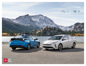
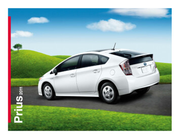
About the PRIUSThe PRIUS 5-door hatchback joins the hybrid model for Toyota. Hybrid Synergy Drivemeans that the vehicle contains a gasoline engine and electric motor for power.The two hybrid power sources are stored on board the vehicle:1. Gasoline stored in the fuel tank for the gasoline engine.2. Electricity stored in a high voltage Hybrid Vehicle (HV) battery pack for theelectric motor.The result of combining these two power sources is improved fuel economy andreduced emissions. The gasoline engine also powers an electric generator to rechargethe battery pack; unlike a pure all electric vehicle, the PRIUS never needs to berecharged from an external electric power source.Depending on the driving conditions one or both sources are used to power the vehicle.The following illustration demonstrates how the PRIUS operates in various drivingmodes. During light acceleration at low speeds, the vehicle is powered by the electric motor.The gasoline engine is shut off. During normal driving, the vehicle is powered mainly by the gasoline engine. Thegasoline engine also powers the generator to recharge the battery pack and to drivethe electric motor. During full acceleration, such as climbing a hill, both the gasoline engine and theelectric motor power the vehicle. During deceleration, such as when braking, the vehicle regenerates the kineticenergy from the front wheels to produce electricity that recharges the battery pack. While the vehicle is stopped, the gasoline engine and electric motor are off, howeverthe vehicle remains on and operational. StartingElectricity Normal DrivingElectricity and gasoline AccelerationElectricity and gasoline(additional electricityextracted from batteries)1 DecelerationCharging batteries StoppingEngine automaticallystopped
PRIUS IdentificationIn appearance, the PRIUS is a 5-door hatchback. Exterior, interior, and enginecompartment illustrations are provided to assist in identification.The alphanumeric 15 character Vehicle Identification Number (VIN) is provided on thefloor under the right side front seat, left side windshield cowl and left side B pillar.Example VIN:JTDKARFU3000101, JTDKBRFU3000101 or JTDKB3FU3000101A PRIUS is identified by the first 8 alphanumeric characters JTDKARFU, JTDKBRFUor JTDKB3FU.Left Side Windshield Cowl, Under the Right Side Front Seat and Left Side B Pillar2
PRIUS Identification (Continued)Exterior logos on the luggage compartment door and each front fender.Gasoline fuel filler door located on the left side rear quarter panel. Exterior Front and Left Side View Exterior Rear and Left Side View3
PRIUS Identification (Continued)Interior The instrument cluster (READY indicator, shift state indicators and warning lights)located in center of the dash and near the base of the windshield.Notice:If the vehicle is shut off, the instrument cluster gauges will be “blacked out”, notilluminated. This illustration is for an LHD modelInterior View READY IndicatorREADY Indicatorfor RHDfor LHDCombination Meter View4
PRIUS Identification (Continued)Engine Compartment 1.8-liter aluminum alloy gasoline engine. Logo on the engine cover.Orange colored high voltage power cables. Engine Compartment Viewfor Nickel-Metal hydride battery: for Lithium-ionbattery:Power Cables5
Hybrid Component Locations & DescriptionsComponentDescription12 Volt Auxiliary Battery Supplies electricity to the electrical components. Hybrid Vehicle (HV) Supplies electrical power to MG1 and MG2 in accordance with theBattery Pack driving conditions of the vehicle. Recharged by MG1 and MG2 in accordance with the SOC and thedriving conditions of the vehicle.Power Cables Connects the HV battery, inverter with converter assembly, hybridvehicle transaxle assembly and compressor with motor assembly.Inverter/DC-DCSteps down the HV battery nominal voltage of DC 201.6 V*1 / DCConverter Converter 207.2 V*2 to approximately DC 14 V in order to supply electricity to for 12 Volt the electrical components, as well as to recharge the auxiliary battery.AuxiliaryBatteryMotorControls the inverter and boost converter in accordance with theGeneratorsignals received from the hybrid vehicle control ECU, thus operatingECUMG1 and MG2 as either a generator or motor.BoostBoosts the HV battery nominal voltage of DC 201.6 V*1 / DC 207.2ConverterV*2 up to a maximum voltage of DC 600 V and vice versa (stepsdown DC 600 V to DC 201.6 V*1 / DC 207.2 V*2).InverterConverts the direct current from the boost converter into alternatingcurrent for MG1 and MG2, and vice versa (from AC to DC).Gasoline Engine Is a high-expansion ratio Atkinson cycle engine which is compatiblewith the hybrid system and which generates drive force for driving andenergy for electricity generation.Electric Motor MG2, which is driven by electrical power from MG1 and the HV battery, generates motive force for the drive wheels. During braking, or when the accelerator pedal is not depressed, itgenerates high-voltage electricity to recharge the HV battery.Electric Generator MG1, which is driven by the engine, generates high-voltage electricityin order to operate MG2 and charge the HV battery. Also, it functionsas a starter to start the engine.A/C CompressorIs driven at a speed calculated by the air conditioning amplifier(with inverter) assembly, receives drive requests from the hybrid vehicle control ECUand takes in, compresses and discharges refrigerant.Fuel Tank and Fuel Line The fuel tank provides gasoline via a fuel line to the engine. The fuel line is routed along the left side under the floor pan.*Numbers in the component column apply to the illustrations on the following page.*1: for Nickel-Metal hydride battery*2: for Lithium-ion battery6
Hybrid Component Locations & Descriptions (Continued)SpecificationsGasoline Engine:Electric Motor:Transmission:HV Battery:71 kW*1 / 72 kW*2, 1.8-liter Aluminum Alloy Engine53 kW (71 HP), Permanent Magnet MotorAutomatic Only201.6 Volt Sealed NiMH Battery*3207.2 Volt Sealed Li-ion- Battery*41,775 kg / 3,915 lbs*51,790 kg / 3,946 lbs*643 liters /11.4 galsSteel UnibodySteel PanelsCurb Weight:Fuel Tank:Frame Material:Body Material:Seating Capacity: 5 passenger*1: for North America, South Korea*2: except North America, South Korea*3: for Nickel-Metal hydride battery*4: for Lithium-ion battery*5: except Europe*6: for Europefor Nickel-Metal hydride battery: for Lithium-ion battery: for Nickel-Metal hydride battery: for Lithium-ionbattery: 7
Hybrid Synergy Drive OperationOnce the READY indicator is illuminated in the combination meter, the vehicle may bedriven. However, the gasoline engine does not idle like a typical automobile and willstart and stop automatically. It is important to recognize and understand the READYindicator provided in the instrument cluster. When illuminated, it informs the driver thatthe vehicle is on and operational even though the gasoline engine may be off and theengine compartment is silent.Vehicle Operation With the PRIUS, the gasoline engine may stop and start at any time while the READYindicator is on. Never assume that the vehicle is shut off just because the engine is off. Always look for theREADY indicator status. The vehicle is shut off when the READY indicator is off.The vehicle may be powered by:1. The electric motor only.2. A combination of both the electric motor and the gasoline engine.for RHDfor LHDCombination Meter READY Indicator8
Hybrid Vehicle (HV) Battery Pack and Auxiliary BatteryThe PRIUS features a high voltage Hybrid Vehicle (HV) battery pack that containssealed Nickel Metal Hydride (NiMH) battery modules*1 or Lithium-ion (Li-ion) batterycells*2.*1: for Nickel-Metal hydride battery*2: for Lithium-ion batteryHV Battery Packfor Nickel-Metal hydride battery: The HV battery pack is enclosed in a metal case and is rigidly mounted to the cabin areaunder the right side front seat. The metal case is isolated from high voltage and concealedby fabric covers in the cabin area. The HV battery pack consists of 28 low voltage (7.2 Volt) NiMH battery modulesconnected in series to produce approximately 201.6 Volts. Each NiMH battery module isnon-spillable and sealed in a metal case. The electrolyte used in the NiMH battery module is an alkaline mixture of potassium andsodium hydroxide. The electrolyte is absorbed into the battery cell plates and will notnormally leak, even in a collision.HV Battery PackBattery pack voltageNumber of NiMH battery modules in the packNiMH battery module voltage201.6 V287.2 Vfor Lithium-ion battery: The HV battery pack is enclosed in a metal case and is rigidly mounted to the cabin areaunder the right side front seat. The metal case is isolated from high voltage and concealedby fabric covers in the cabin area. The HV battery pack consists of 56 low voltage (3.6 Volt) Li-ion battery cells connected inseries to produce approximately 207.2 Volts. Each Li-ion battery cell is non-spillable and ina sealed case. The electrolyte used in the Li-ion battery cells is a flammable organic electrolyte. Theelectrolyte is absorbed into the battery cell separator and will not normally leak, even in acollision.HV Battery PackBattery pack voltageNumber of Li-ion battery cells in the packLi-ion battery cell voltageComponents Powered by the HV Battery Pack Electric MotorPower CablesA/C CompressorElectric GeneratorInverter/Converter- DC-DC Converter for 12 Volt Auxiliary Battery9207.2 V563.6 V
Hybrid Vehicle (HV) Battery Pack and Auxiliary Battery (Continued)HV Battery Pack Recycling The HV battery pack is recyclable. Contact either your Toyota Distributor as mentioned onHV battery Caution Label or the nearest Toyota dealer.Auxiliary Battery The PRIUS also contains a sealed lead-acid 12 Volt battery. This 12 Volt auxiliary batterypowers the vehicle electrical system similar to a conventional vehicle. As with otherconventional vehicles, the auxiliary battery is grounded to the metal chassis of the vehicle. The auxiliary battery is located in the luggage compartment area. It is concealed by a plasticresin cover on the right side in the battery compartment.for Nickel-Metal hydride battery:for Lithium-ion battery:12 Volt Auxiliary Battery Mounted inEngine Compartment Area201.6*1 / 207.2*2 Volt HV Battery Packfor Nickel-Metal hydride battery:for Lithium-ion battery:HV Battery Pack Mounted in Cabin Area*1: for Nickel-Metal hydride battery*2: for Lithium-ion battery10
High Voltage SafetyThe HV battery pack powers the high voltage electrical system with DC electricity. Positive andnegative orange colored high voltage power cables are routed from the battery pack, under thevehicle floor pan, to the inverter/converter. The inverter/converter contains a circuit that booststhe HV battery voltage from 201.6*1, 207.2*2 to 600 Volts DC. The inverter/converter creates3-phase AC to power the motor. Power cables are routed from the inverter/converter to eachhigh voltage motors (electric motor, electric generator, and A/C compressor). The followingsystems are intended to help keep occupants in the vehicle and emergency responders safe fromhigh voltage electricity:*1: for Nickel-Metal hydride battery*2: for Lithium-ion batteryHigh Voltage Safety System A high voltage fuse * provides short circuit protection in the HV battery pack. Positive and negative high voltage power cables * connected to the HV battery pack arecontrolled by 12 Volt normally open relays *. When the vehicle is shut off, the relays stopelectricity flow from leaving the HV battery pack.WARNING:・ The high voltage system may remain powered for up to 10minutes after the vehicle is shut off or disabled. To preventserious injury or death from severe burns or electric shock,avoid touching, cutting, or opening any orange high voltagepower cable or high voltage component. Both positive and negative power cables * are insulated from the metal body. Highvoltage electricity flows through these cables and not through the metal vehicle body.The metal vehicle body is safe to touch because it is insulated from the high voltagecomponents. A ground fault monitor * continuously monitors for high voltage leakage to the metalchassis while the vehicle is running. If a malfunction is detected, the hybrid vehiclecomputer * will illuminate the master warning lightin the instrument cluster and amessage indicating that the hybrid system is malfunctioning will be displayed on themulti-information display. The HV battery pack relays will automatically open to stop electricity flow in a collisionsufficient to activate the SRS.*Numbers apply to the illustration on the following page.11
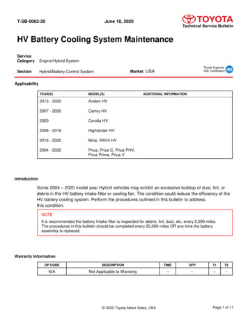
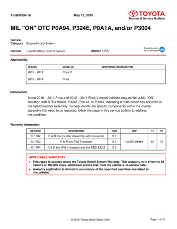
High Voltage Safety (Continued)Service Plug Grip The high voltage circuit is cut by removing the service plug grip (see page 16).Hybrid Vehicle Computer➍0.0Volts DCA/CCompressor➋➋ElectricGenerator12 VoltsAuxiliaryBattery❸Inverter/Converter0.0Volts DCElectricMotor0 Volts AC3-Phase❸➊HV Battery PackHigh Voltage Safety System – Vehicle Shut Off (READY-OFF)Hybrid Vehicle Computer201.6*1207.2*2Volts 12 VoltsAuxiliaryBattery201.6*1207.2*2Volts DCElectricMotor600 VoltsAC Max3-PhaseHV Battery PackHigh Voltage Safety System – Vehicle On and Operational (READY-ON)*1: for Nickel-Metal hydride battery*2: for Lithium-ion battery12
Precaution to be observed when dismantling the vehicleWARNING:・ The high voltage system may remain powered for up to 10minutes after the vehicle is shut off or disabled. To preventserious injury or death from severe burns or electric shock,avoid touching, cutting, or opening any orange high voltagepower cable or high voltage component.Necessary Items Protective clothing such as insulated gloves (electrically insulated), rubber gloves, safety goggles,and safety shoes.Insulating tape such as electrical tape that has a suitable electrical insulation rating.Before wearing insulated gloves, make sure that they are not cracked, ruptured, torn, or damaged inany way. Do not wear wet insulated gloves.An electrical tester that is capable of measuring DC 750 Volts or more.13
Spillsfor Nickel-Metal hydride battery:The PRIUS contains the same common automotive fluids used in other non-hybrid Toyota vehicles,with the exception of the NiMH electrolyte used in the HV battery pack. The NiMH battery electrolyteis a caustic alkaline (pH 13.5) that is damaging to human tissues. The electrolyte, however, is absorbedin the cell plates and will not normally spill or leak out even if a metal battery module is cracked.A catastrophic crash that would breach both the metal battery pack case and a metal battery modulewould be a rare occurrence.A caustic alkaline is at the opposite end of the pH scale from a strong acid. A safe (neutral) substance isapproximately in the middle of this scale. Adding a weak acidic mixture, such as a dilute boric acidsolution or vinegar, to the caustic alkaline electrolyte will cause the electrolyte to be neutralized. This issimilar but opposite to the use of baking soda to neutralize a lead-acid battery electrolyte spill.A Toyota Product Safety Data Sheets (PSDS) is attached to this document. Handle NiMH electrolyte spills using the following Personal Protective Equipment (PPE): Splash shield or safety goggles. A fold down face shield is not acceptable for acid orelectrolyte spills. Rubber, latex or nitrile gloves.Apron suitable for alkaline.Rubber boots.Neutralize NiMH electrolyte. Use a boric acid solution or vinegar.Boric acid solution - 800 grams boric acid to 20 liters water or 5.5 ounces boric acid to1 gallon of water.14
for Lithium-ion battery:The PRIUS hybrid contains the same common automotive fluids used in other non-hybrid Toyotavehicles, with the exception of the Li-ion electrolyte used in the HV battery pack. The electrolyte usedin the Li-ion battery cells is a flammable organic electrolyte. The electrolyte is absorbed into the batterycell separators, even if the battery cells are crushed or cracked, it is unlikely that liquid electrolyte willleak. Any liquid electrolyte that leaks from a Li-ion battery cell quickly evaporates.WARNING:・ The Li-ion battery contains organic electrolyte. Only a smallamount may leak from the batteries which may irritate the eyes,nose, throat, and skin.・ Contact with the vapor produced by the electrolyte may irritatethe nose and throat.・ To avoid injury by coming in contact with the electrolyte or vapor,wear personal protective equipment for organic electrolyteincluding SCBA or protective mask for organic gases. Handle Li-ion electrolyte spills using the following Personal Protective Equipment (PPE): Splash shield or safety goggles. A fold down face shield is not acceptable for acid orelectrolyte spills. Rubber gloves or gloves suitable for organic solvents.Apron suitable for organic solvents.Rubber boots or boots suitable for organic solvents.Protective mask for organic gases or SCBA.15
Dismantling the vehicleThe following 4 pages contain general instructions for use when working on a PRIUS.Read these instructions before proceeding to the HV battery removal instructions on page 21.WARNING:・ The high voltage system may remain powered for up to 10minutes after the vehicle is shut off or disabled. To preventserious injury or death from severe burns or electric shock,avoid touching, cutting, or opening any orange high voltagepower cable or any high voltage component.1. Shut off the ignition (READY indicator is off).Then disconnect the cable from the auxiliarybattery negative (-) terminal.(1) Loosen the nut, and disconnect the cable fromthe negative (-) auxiliary battery terminal.2. Remove the battery service hole cover.(1) Remove the clip.(2) Disengage the 5 claws and remove thebattery service hole cover.16
3. Remove the service plug grip.Caution:・Wear insulated gloves.・Do not inspect or service the high voltagesystem with the service plug grip installed.・To reduce the risk of electric shock, make sure to remove the service plug grip tocut off the high voltage circuit before servicing the vehicle.・To reduce the risk of electric shock, make sureto wait at least 10 minutes after removing theservice plug grip to fully discharge the highvoltage capacitor inside the inverter withconverter assembly.・Keep the removed service plug grip in your pocket to prevent other technicians fromaccidentally installing it while you are servicing the vehicle.・Place a "HIGH VOLTAGE WORK IN PROGRESS. DO NOT TOUCH." sign, in order toprevent other technicians from accidentally reconnecting the power while work is inprogress.Notice:・After removing the service plug grip, turning the power switch on (READY) may cause amalfunction. Do not turn the power switch on (READY) unless instructed by the repair manual.・Do not touch the terminals of the service plug grip.Hint:Waiting for at least 10 minutes is required to discharge the high voltage capacitor inside theinverter with converter assembly.17
(1) While wearing insulated gloves, rotate the handle of the service plug grip and remove theservice plug grip as indicated by the arrows, in the order shown in the illustration.for NICKEL METAL HYDRIDE BATTERY:231for LITHIUM-ION BATTERY:2314. Carry the removed service plug grip in your pocket to prevent other staff fromaccidentally reinstalling it while you are dismantling the vehicle.5. Make other staff aware that a high-voltage system is being dismantled by using thefollowing sign: CAUTION: HIGH-VOLTAGE. DO NOT TOUCH (see page 20).IG2-MAIN fuse6. If the service plug grip cannot be removed dueto damage to the vehicle, remove theIG2-MAIN fuse (25 A).Caution:This operation shuts off the HV system. Besure to wear insulated gloves because highvoltage is not shut off inside the HV battery.When it is possible to remove the service pluggrip, remove it and continue the procedure.18
7. After disconnecting or exposing a high-voltageconnector or terminal, insulate it immediatelyusing insulating tape. Before disconnecting ortouching a bare high-voltage terminal, wearinsulated gloves.8. Check the HV battery and nearby area for leakage.If you find any liquid, it may be strong alkalineelectrolyte. Wear rubber gloves and goggles and neutralize the liquid using a saturatedboric acid solution or vinegar. Then wipe up the liquid using waste rags etc.9. If the electrolyte comes into contact with your skin, wash the skin immediately using asaturated boric acid solution or a large amount of water. If the electrolyte adheres to anyarticle of clothing, take the clothing off immediately.10. If the electrolyte comes into contact with your eye(s), call out loudly for help. Do notrub your eye(s). Instead, wash the eye(s) with a dilute boric acid solution or a largeamount of water and seek medical care.11. With the exception of the HV battery, remove parts by following procedures which aresimilar to conventional Toyota vehicles. For the removal of the HV battery, refer to thefollowing pages.19
20
Removal of HV batteryWARNING:・ Be sure to wear insulated gloves when handling high-voltageparts.・ Even if the vehicle is shut off and the relays are off, be sure toremove the service plug grip before performing any furtherwork.・ Power remains in the high voltage electrical system for 10minutes even after the HV battery pack is shut off because thecircuit has a condenser that stores power.・ Make sure that the tester reading is 0 V before touching anyhigh-voltage terminals which are not insulated.・ The SRS may remain powered for up to 90 seconds after thevehicle is shut off or disabled. To prevent serious injury ordeath from unintentional SRS deployment, avoid cutting theSRS components.1. SHUT OFF IGINITION (READY indicator is off)2. REMOVE AUXILIARY BATTERY(1) Loosen the nut and disconnect the cable from thenegative (-) auxiliary battery terminal.(2) Disengage the 2 claws and open the battery terminalcap.(3) Loosen the nut and disconnect the cable from thepositive ( ) auxiliary battery terminal.21
(4) Remove the bolt.(5) Remove the No. 2 battery clamp as shown in theillustration.(6) Remove the auxiliary battery.3. REMOVE BATTERY SERVICE HOLE COVER(1) Remove the clip.(2) Disengage the 5 claws and remove the batteryservice hole cover.22
4. REMOVE SERVICE PLUG GRIPCaution:・Wear insulated gloves.・Do not inspect or service the high voltagesystem with the service plug grip installed.・To reduce the risk of electric shock, make sure to remove the service plug grip tocut off the high voltage circuit before servicing the vehicle.・To reduce the risk of electric shock, make sureto wait at least 10 minutes after removing theservice plug grip to fully discharge the highvoltage capacitor inside the inverter withconverter assembly.・Keep the removed service plug grip in your pocket to prevent other technicians fromaccidentally installing it while you are servicing the vehicle.・Place a "HIGH VOLTAGE WORK IN PROGRESS. DO NOT TOUCH." sign, in order toprevent other technicians from accidentally reconnecting the power while work is inprogress.Notice:・After removing the service plug grip, turning the power switch on (READY) may cause amalfunction. Do not turn the power switch on (READY) unless instructed by the repair manual.・Do not touch the terminals of the service plug grip.Hint:Waiting for at least 10 minutes is required to discharge the high voltage capacitor inside theinverter with converter assembly.23
(1) While wearing insulated gloves, rotate the handle of the service plug grip and remove theservice plug grip as indicated by the arrows, in the order shown in the illustration.for NICKEL METAL HYDRIDE BATTERY:231for LITHIUM-ION BATTERY:2315.REMOVE WINDSHIELD OUTSIDE MOULDINGLH(1) Using a moulding remover, disengage the 12 clawsand remove the windshield outside moulding.6.REMOVE WINDSHIELD OUTSIDE MOULDINGRHHint:Use the same procedure as for the LH side.24
7.REMOVE FRONT WIPER ARM HEAD CAP(1) Using a screwdriver, disengage the 3 claws toremove the front wiper arm head cap.Hint:Use the same procedure for the RH side and LH side.8.REMOVE FRONT WIPER ARM AND BLADEASSEMBLY LH(1) Remove the nut and front wiper arm and bladeassembly LH.9.REMOVE FRONT WIPER ARM AND BLADEASSEMBLY RH(1) Remove the nut and front wiper arm and bladeassembly RH.10. REMOVE COWL WATER EXTRACT SHIELD LH(1) Disengage the 2 claws and 2 guides to remove thecowl water extract shield LH as shown in theillustration.11. REMOVE COWL WATER EXTRACT SHIELD RHHint:Use the same procedure as for t
About the PRIUS The PRIUS 5-door hatchback joins the hybrid model for Toyota. Hybrid Synergy Drive means that the vehicle contains a gasoline engine and electric motor for power. The two hybrid power sources are stored on board the vehicle: 1. Gasoline stored in the fuel tank for the gasoline engine. 2.