Transcription
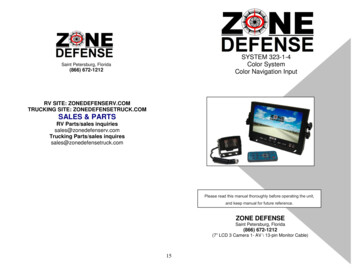
SYSTEM 323-1-4Color SystemColor Navigation InputSaint Petersburg, Florida(866) 672-12127 INCH FLAT MONITORRV SITE: ZONEDEFENSERV.COMTRUCKING SITE: ZONEDEFENSETRUCK.COMSALES & PARTSRV Parts/sales inquiriessales@zonedefenserv.comTrucking Parts/sales inquiressales@zonedefensetruck.comPlease read this manual thoroughly before operating the unit,and keep manual for future reference.ZONE DEFENSESaint Petersburg, Florida(866) 672-1212(7” LCD 3 Camera 1- AV \ 13-pin Monitor Cable)15
Optional EquipmentTABLE OF CONTENTSWindshield PedestalMonitor Mount - Part # 400ASafety Information . 3-4System Features . 5System Components . 6-7System Operations . 8Connections . 9Menu Operations .11-13Trouble Shooting. 14Optional Equipment . 15E-Z Windshield Mount allows for themonitor to be removed when not inuse.Zone Defense Truck/5thWheel Coil Cable - Part# 359AAuxiliary Coiled Camera Cable With 2ReceptaclesZone Defense Camera Cables20 Meter Cable Part #35815 Meter Cable Part #358A10 Meter Cable Part #358bZONE DEFENSETM offers systems to meet any need and pricepoint within the RV/Trucking Industries. Our systems offerunparalleled features designed for professional drivers. ZoneDefense develops, manufactures and markets, among otherdevices: products and applications developed to transmit voice,video, audio and data either individually or in any combinationwith one another. The Company has also developed,manufactured and marketed different kinds of underwater videocameras, lights and accessories for the marine, commercial,transportation, trucking and consumer retail markets.Color CameraPart # 312-313COptional I/R Non-Color camera w/cables and 5m camera CableDome CameraPart # 312-313DColor infrared camera w/ adjustableangle view 5m camera CableOPTIONAL TRUCK - TRAILER CABLEZone Defense Trailer Coil CableAuxiliary Coiled 2-Camera Cable with 2 Receptacles for ZoneDefense Camera Cables. Part# 359A2BV 5/08114
SAFETY INFORMATIONTECHNICAL SUPPORTSymptomSmall UnstableimageBlack imageWhite imageBlurred imageEngine noiseor Static linesNo lightdisplayed onmonitorNo imageBefore installing and operating read manualTrouble Shooting ChartCauseSolutionCheck the voltage ofMonitor improperpower supplyvoltageMonitor impropervoltageMonitor/CameraDirty camera lensMonitorBroken fuse or lowbrightness levelNo power orunpluggedconnectorImportant! – Please Read This Manual BeforeInstalling!Congratulations on the purchase of your Zone DefenseTMSystem. Zone Defense is a leader in vehicle observationsystems. When properly installed and used, your System 323-1-4is designed to provide you with years of trouble-free operation.This manual contains important information required to properlyinstall and operate the unit. Please read this manual thoroughlybefore beginning.Check fuse, check powercable, wires orconnections (look forloose or broken wires)Check main systemcable. Make sureall connectors areconnected properly.If ok, check 4 pin camera/monitor cableClean camera lensCheck ground and 12VDC source.Check the brightness hasbeen turned to the lowestlevelCheck power and checkfor unplugged or brokencamera cableAll Zone Defense products are strictly intended to be installed asa supplement and Zone Defense observation systems and/orproducts are not intended for use as substitutes for rear-viewmirror devices, or for any other standard motor vehicle equipmentrequired to be installed on vehicles by law. Zone Defenseproducts contribute to improving the vehicle operator’s field ofview. Our products are no substitute for proper defensive drivingtechniques, observance of traffic laws and motor vehicle safetyregulations.Warnings!Installation LocationIt is unlawful in most jurisdictions for any person(s) to drive amotor vehicle equipped with a television viewer/screen located atany point forward of the back of the driver’s seat (or in anylocation that is visible, directly or indirectly), to the driver whileoperating the vehicle. The system 323-1-4 is designed to be usedprimarily as a rear observation device. In any installations whereSystems 323-1-4 products are used to display televisionbroadcasts or recorded video playback, installation location mustadhere to local laws and regulations.Technical SupportFor help with Zone Defense technical support, please email us.Email: fenseRV.ComPhone support: 866-672-1212RV Parts/Sales Inquiries Sales@ZoneDefenseRV.ComTrucking Parts/Sales Inquires Sales@ZoneDefenseTruck.Com13TamperingTo prevent electrical shock, DO NOT OPEN THE MONITORCASE. There are potentially harmful voltages inside the monitor.There are no user serviceable parts inside any of thecomponents of the Zone Defense products. If tampering is2 detected, the warranty will be considered void.
3 SYSTEMFACTORY PRE SET FOR APPLICATIONDO NOT ADJUSTWARNING Do not place heavy object on cables or coverthem with rugs or carpet. Do not place cables where they can be pinchedor stepped on. Designed as a driving aid. Watching videos,broadcasts, DVDs and/or any images otherthan intended driving assistance cameras isprohibited.The BLUE BACK, HORIZONTAL, VERTICAL, ZOOM functions willdisplay on the screen as illustrated below: COLOR-SYS(pre factory adjusted for your application, do not adjust)SYSTEMCAUTION To avoid damage to electronic circuit, stopusing this product while doing welding work tothe vehicle and/or trailers. Never immerse any component in water, anddo not employ spray cleaners. When cleaning,use damp lint-free cloth only. Connect this unit only to other compatibledevices. Make sure all cables are connected properly;improper cable connections may damage thecamera and the monitor. Make sure all cables are connected firmly. Cables should not be allowed to touch hot orrotating parts, such as engine, ventilator, etc. Do not locate the monitor near heat generatingvents or devices. Turn off power to the monitor when connectingthe camera.COLOR SYSBLUE BACKHORIZONTALVERICALZOOMSELECTPRE SETON0ADJUSTConnection of AV OutputConversion AdapterAlign the small end of AV conversionadapter with AV2 jack on front panel ofthe display, and then plug in RCA.Monitors are not designed to be waterproof. Exposureto water, such as rain, may damage the unit.312
Press CH- to select SCALE.SYSTEM TDisplay Device: 7” Color TFT-LCDAudio Output: Max. 1WLoudspeaker: One 4.0cm round loudspeakerPower Supply: 12v-32vOuter dimensions: 182mm(W) x 122mm(H) x 26(T) without back shield; 198mm(W) x 138mm(H)x 31mm(T) with back shieldDot Pitch: 0.321 (W ) x 0.372 (H)Resolution: 480x3 RGB x234Contrast: 250:1Brightness: 450cd/m²Viewing Angle: U: 30 / D: 60, R/L:60Operating Temperature -20 70C, RH90%Storage temperature -30 80C, RH90%ENGNORMALNORMALNORMALNORMALNORMALADJUST1 / 3” COLOR CCD SENSOR SPECIFICATIONSS (REAR)With Audio and IRTV System: NTSCEffective Pixels: 512 x 492 pixelsSensing Area: 4.9mm x 3.7mmScanning System: 2:1InterlaceSync. System: InternalResolution: 420TV linesHorizontal Sync. Frequency: 15.734KHzVertical Sync. Frequency: 60HzMinimum Illumination: 0 LuxBLC: AutoMicrophone: YesVideo Output: 1.0vp-p, 75OhmAGC: AutoWhite Balance: AutoS/N Ratio: Better than 48dBElectronic Shutter: 1/60 1/10,000Current Consumption: Max. 300mAPower Supply: DC12VOperating Temperature: -20 C 70 C, RH95% MAXStorage Temperature: -40 C 80 C,RH95% MAXLens: f 2.8Lens Angle: 100 Vertical 130 Horizontally (May vary depending on system configuration)Press\to select ON/OFF. Scale refers to thereversing distance indicator display on the monitor. Press CH- to select NORMALNORMALNORMALNORMALNORMAL1 / 3” COLOR CCD SENSOR SPECIFICATIONS(SIDE OPTIONAL)Without Audio Image Device: SHARPEffective Pixels: 512 x 582 pixelsSensing Area: 4.9mm x 3.7mmScanning System: 2:1InterlaceSync. System: InternalResolution: 420TV linesHorizontal Sync. Frequency: 15.625KHz / 15.734KHzVertical Sync. Frequency: 50Hz / 60HzMinimum Illumination: 0 Lux/F1.2 with IRVideo Output: 1.0vp-p, 75OhmGamma Consumption: 0.45AGC: AutoBLC: AutoWhite Balance: AutoS/N Ratio: Better than 48dBElectronic Shutter: 1/60(NTSC) / 1/50(PAL) 1/10,000 SecondsPower Supply: DC12VCurrent Consumption: Max. 300mAOperating Temperature: -20 C 70 C, RH95% MAXStorage Temperature: -40 C 80 C,RH95% MAXLens: f 3.6mm / F 2.0Lens Angle: 120 (Standard)ADJUSTto select NORMAL / MIRROR114
ALL SPECIFICATIONS ARE SUBJECT TO CHANGESYSTEM COMPONENTS Press CH- to select HT50HUE50!!!!!!!!!!!!!!!!!. 50I/F Remote7-Inch Flat PanelSELECTPressADJUST/to adjust the Brightness2. OptionsInfrared Color w/ audioRear CameraThe LANG, SCALE, CAM1, CAM2, CAM3, DVD options displayedon the screens as illustrated below:20-Meter CameraCableOPTION12 volt DC Power13-pin AV MonitorCableLANGSCALECAM1CAM2CAM2DVDUniversal TFlush MountPress\to select ENGLISH / JAPANESE / FRENCH /PORTUGESE / SPAINISH / RUSSIAN / TURKISH / GERMAN /ITALIAN / BULGARIAN / ARIBIC.510
MENU OPERATIONSMONITORThis monitor can be mounted in dash, hanging or seating inany position, which ever is suitable to the driver to observe theimages. Take care not to block any necessary viewing areawhen mounting.1. MENU:MENU:Press MENU in turn to display options as follows:1. PICTURE2. OPTION3. SYSTEMMounting Monitor1.After determining the monitor location, position themonitor support bracket, mark the bolt hole location and thendrill the holes. Be careful not to drill into any other surface thatmay be hidden.2.If supplied, use washers on mounting screws. Attachmonitor bracket. Check installation before mounting monitor.3.Mount the monitor to the support bracket with supplied 4angle adjustment screws.4. Connect one end of the power cable (wire) to the properconnections. Connect the other end of the power cable (plug)to the monitor, connect the monitor and the camera with thesystem connecting cable.(1) Picture(Note Color adjustment valid on Navigation input channel only)The VOLUME, BRIGHTNESS, CONTRAST, COLOR, SHARP, HUE(NTSC Only) options will display on the screen as illustrated below. Press CH- to select HT50HUE50!!!!!!!!!!!!!!!!!. 50PressSELECT/Camera MountingWaterproof CameraConnectorsADJUSTto adjust the VOLUME LevelSecondary Waterproof SleeveSlides Over ConnectionGrommet To SealThrough Vehicle Exterior95/8-inch hole needed to pass connector through theexterior wall. Be careful not to drill a hole so large thatthe grommet will not seal. Before drilling make surethere are no obstacles in the way in the drill bit. Check tomake sure wall thickness is suitable for weatherproofinggrommet. Use proper hardware to mount camera6 bracket.
CONNECTION OPERATIONSMONITOR / REMOTE OPERATIONSCH-POWERMENUSELAuxiliary A/V Input123465879101. Remote Signal Receiver Window2. Power Indicator Light3. Power Off/On button4. Brightness Increase Options Control Button5. Brightness Decrease6. Channel – (Down button)7. Menu Control Button8. SEL Switches between AV 1, AV 2, & AV39. Video out10. Earphone JackMENUSELECTION ( )MENUMUTEPOWERMUTEFLIPHORIZONTALRED wire (with in-line fuse)power supply DC / 12-32V ( ).BLACK wire for GND (-).BROWN wire to positive powersupply of backup light.WHITE (activates camera 1) wire topositive power supply of left directionallight (if side camera used).POWERBLUE (activates camera 2) wire topositive power supply of rightdirectional light (if side camera used).FLIP VERTICALCAMERA 3 LLPICTUREMODELANGUAGESELECTIONMENUSELECTION (-)CHCAMERA 2 [Right-side]CAMERA 1 [Left-side]MODELANGCALLTIMERSELTIMERAV1/AV2 /AV3SWITCH78
This manual has been provided courtesy ofMy RV Works, Inc.www.myrvworks.comYou can find more RV service manuals here:www.myrvworks.com/manualsOver the years of running a mobile RV repair service, having a dedicated placeto access service manuals for all the different appliances and componentsfound on RVs was something that I always had a desire to create.I hope this resource makes your RV repairs easier, as it has mine, but pleasebe careful and follow proper safety practices when attempting to repairyour own RV.If in doubt, please consult with a professional RV technician!DARREN KOEPP - OWNER, MY RV WORKS, INC.All service manuals provided on www.myrvworks.com are believed to bereleased for distribution and/or in the public domain.
MONITOR Display Device: 7" Color TFT-LCD Audio Output: Max. 1W Loudspeaker: One 4.0cm round loudspeaker Power Supply: 12v-32v . Check installation before mounting monitor. 3. Mount the monitor to the support bracket with supplied 4 angle adjustment screws. 4. Connect one end of the power cable (wire) to the proper


