Transcription
ICE MAKERUse & Care GuideTable of Contents . 22313687B
TABLE OF CONTENTSICE MAKER SAFETY.2INSTALLATION INSTRUCTIONS .3Unpack the Ice Maker.3Location Requirements .3Electrical Requirements .3Water Supply Requirements .4Leveling .4Connect Water Supply.4Drain Connection .5Ice Maker Door.6Normal Sounds .7ICE MAKER USE.8How Your Ice Maker Works .8Using the Controls.8ICE MAKER CARE.8Cleaning.8Vacation and Moving Care.10TROUBLESHOOTING .11Ice Maker Operation.11Ice Production .11Ice Quality.12Plumbing Problems .12ASSISTANCE OR SERVICE .12ICE MAKER SAFETYYour safety and the safety of others are very important.We have provided many important safety messages in this manual and on your appliance. Always read and obey all safetymessages.This is the safety alert symbol.This symbol alerts you to potential hazards that can kill or hurt you and others.All safety messages will follow the safety alert symbol and either the word “DANGER” or “WARNING.”These words mean:DANGERWARNINGYou can be killed or seriously injured if you don't immediatelyfollow instructions.You can be killed or seriously injured if you don't followinstructions.All safety messages will tell you what the potential hazard is, tell you how to reduce the chance of injury, and tell you what canhappen if the instructions are not followed.IMPORTANT SAFETY INSTRUCTIONSWARNING: To reduce the risk of fire, electric shock, or injury when using your ice maker, follow these basicprecautions: Plug into a grounded 3 prong outlet. Disconnect power before cleaning. Do not remove ground prong. Disconnect power before servicing. Do not use an adapter. Replace all parts and panels before operating. Do not use an extension cord. Use two or more people to move and install ice maker.SAVE THESE INSTRUCTIONS2
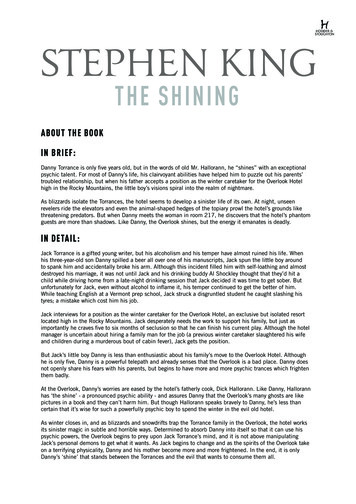
INSTALLATION INSTRUCTIONS Unpack the Ice MakerBe sure the drain line (on some models) is not pinchedbetween the ice maker and the cabinet.WARNINGExcessive Weight HazardUse two or more people to move and install ice maker.11¹ ₂"(29.2 cm)Failure to do so can result in back or other injury.34"(86.4 cm)Min.34¹ ₂"(87.6 cm)Max.Removing Packaging MaterialsRemove tape and glue from your ice maker before using. To remove any remaining tape or glue from the exterior of theice maker, rub the area briskly with your thumb. Tape or glueresidue can also be easily removed by rubbing a smallamount of liquid dish soap over the adhesive with yourfingers. Wipe with warm water and dry. After you remove all of the packaging materials, clean the insideof your ice maker before using it. See the cleaning instructions inthe “Ice Maker Care” section.Location Requirements To ensure proper ventilation for your ice maker, the front sidemust be completely unobstructed. The unit may be closed-inon the top and three sides, but the installation should allowthe ice maker to be pulled forward for servicing if necessary. Installation of the ice maker requires a cold water supply inletof ¹ ₄" (6.35 mm) OD soft copper tubing with a shutoff valveand either a gravity-drain system or condensate pump tocarry the water to an existing drain. Choose a well ventilated area with temperatures above 55 F(13 C) and below 110 F (43 C). Best results are obtainedbetween 70 F (21 C) and 90 F (32 C). This unit must be installed in an area protected from theelements, such as wind, rain, water spray, or drip. When installing the ice maker under a counter, follow therecommended opening dimensions shown. Place electricaland plumbing fixtures in the recommended location asshown.28¹ ₂"(72.4 cm)9"3¹ ₂"(22.9 cm)(8.9 cm)24"(60.1 cm)Do not use sharp instruments, rubbing alcohol, flammablefluids, or abrasive cleaners to remove tape or glue. Do notuse chlorine bleach on the stainless steel surfaces of the icemaker. These products can damage the surface of your icemaker.Cleaning Before UseAB15"(38.1 cm)A. Recommended location for electricaland plumbing fixturesB. Floor level You should choose a location where the floor is even. It isimportant for the ice maker to be level in order to workproperly. If needed, you can adjust the height of the ice makerby changing the height of the leveling legs. See “Leveling.”Electrical RequirementsWARNINGElectrical Shock HazardPlug into a grounded 3 prong outlet.Do not remove ground prong.Do not use an adapter.Do not use an extension cord.Failure to follow these instructions can result in death,fire, or electrical shock.NOTE: Be sure the power supply cord is not pinched betweenthe ice maker and the cabinet. Be sure the water supply line is not pinched between theice maker and the cabinet.Before you move your ice maker into its final location, it isimportant to make sure you have the proper electricalconnection:A 115 Volt, 60 Hz., AC only, 15- or 20-amp electrical supply,properly grounded in accordance with the National ElectricalCode and local codes and ordinances, is required.3
It is recommended that a separate circuit, serving only your icemaker, be provided. Use a receptacle which cannot be turned offby a switch or pull chain.IMPORTANT: If this product is connected to a GFCI (GroundFault Circuit Interrupter) protected outlet, nuisance tripping of thepower supply may occur, resulting in loss of cooling. Ice qualitymay be affected. If nuisance tripping has occurred, and if thecondition of the ice appears poor, dispose of it.Recommended grounding methodFor your personal safety, this appliance must be grounded. Thisappliance is equipped with a power supply cord having a 3 pronggrounding plug. To minimize possible shock hazard, the cordmust be plugged into a mating, 3 prong, grounding-type wallreceptacle, grounded in accordance with the National ElectricalCode and local codes and ordinances. If a mating wall receptacleis not available, it is the personal responsibility of the customer tohave a properly grounded, 3 prong wall receptacle installed by aqualified electrician.1. Move the ice maker to its final location.NOTE: If this is a built-in installation, move the ice maker asclose as possible to the final location.2. Place a carpenter’s level on top of the product to see if the icemaker is level from front to back and side to side.3. Push up on the top front of the ice maker, and then locate theleveling screws that are on the bottom front of the ice maker.4. Using an adjustable wrench, change the height of the legs asfollows: Turn the leveling leg to the right to lower that side of theice maker. Turn the leveling leg to the left to raise that side of the icemaker.NOTE: The ice maker should not wobble. Use shims to addstability when needed.Water Supply RequirementsA cold water supply with water pressure of between 30 and120 psi (207 and 827 kPa) is required to operate the ice maker. Ifyou have questions about your water pressure, call a licensed,qualified plumber.Reverse Osmosis Water SupplyIMPORTANT: The pressure of the water supply coming out of areverse osmosis system going to the water inlet valve of the icemaker needs to be between 30 and 120 psi (207 and 827 kPa).If a reverse osmosis water filtration system is connected to yourcold water supply, the water pressure to the reverse osmosissystem needs to be a minimum of 40 to 60 psi (276 to 414 kPa).The reverse osmosis system must provide 1 gal. (3.79L) of waterper hour to the ice maker for proper ice maker operation.If the water pressure to the reverse osmosis system is less than40 to 60 psi (276 to 414 kPa): Check to see whether the sediment filter in the reverseosmosis system is blocked. Replace the filter if necessary. LevelingIt is important for the ice maker to be level in order to workproperly. Depending upon where you install the ice maker, youmay need to make several adjustments to level it. You may alsouse the leveling legs to lower the height of the ice maker forundercounter installations.Tools needed:Gather the required tools and parts before starting installation. 9" levelAdjustable wrenchNOTE: It is easier to adjust the leveling legs if you have anotherperson to assist you.Connecting the water line1. Turn off main water supply. Turn on nearest faucet longenough to clear line of water.2. Find a ¹ ₂" (12.70 mm) to 1¹ ₄" (3.18 cm) vertical cold water4Connect Water SupplyRead all directions thoroughly before you begin.IMPORTANT: Plumbing shall be installed in accordance with theInternational Plumbing Code and any local codes andordinances. Use copper tubing and check for leaks. Install copper tubing only in areas where temperatures willremain above freezing.Allow the storage tank on the reverse osmosis system to refillafter heavy usage.If you have questions about your water pressure, call a licensed,qualified plumber. 5. Push up on the top rear of the ice maker and locate theleveling legs that are on the bottom rear of the ice maker.6. Follow the instructions in Step 4 to change the height of thelegs.7. Use a carpenter’s level to recheck the ice maker to see that itis even from front to back and side to side. If the ice maker isnot level, repeat steps 2 to 5. If the ice maker is level, go tothe “Connect Water Supply” section.Tools needed:Gather the required tools and parts before starting installation.Read and follow the instructions provided with any tools listedhere. Flat-blade screwdriver ⁷ ₁₆" and ¹ ₂" open-end wrenches or two adjustable wrenches ¹ ₄" nut driver ¹ ₄" drill bit Hand drill or electric drill properly groundedNOTE: Your ice maker dealer has a kit available with a ¹ ₄"(6.35 mm) saddle-type shutoff valve, a union, and copper tubing.Before purchasing, make sure a saddle-type valve complies withyour local plumbing codes. Do not use a piercing-type or ³ ₁₆"(4.76 mm) saddle valve which reduces water flow and clogs moreeasily.pipe near the ice maker.NOTE: Horizontal pipe will work, but the following proceduremust be followed: Drill on the top side of the pipe, not thebottom. This will help keep water away from the drill. Thisalso keeps normal sediment from collecting in the valve.
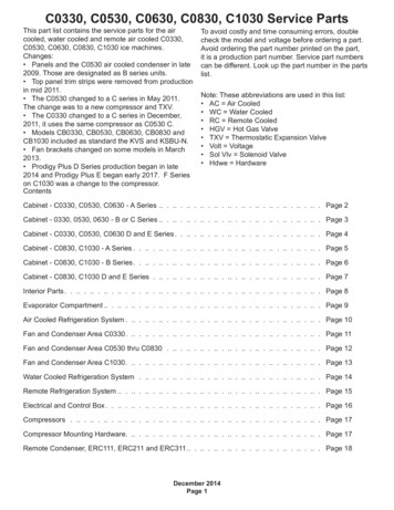
3. Using a grounded drill, drill a ¹ ₄" (6.35 mm) hole in the coldwater pipe you have selected.4. Fasten shutoff valve to cold water pipe with pipe clamp. Besure outlet end is solidly in the ¹ ₄" (6.35 mm) drilled hole in thewater pipe and that the washer is under the pipe clamp.Tighten packing nut. Tighten the pipe clamp screws slowlyand evenly so washer makes a watertight seal. Do notovertighten the pipe clamp or you may crush cold water pipeif it is soft copper tubing. Do not use a piercing-type or ³ ₁₆"(4.76 mm) saddle-type valve which reduces water flow andclogs more easily.5. Now you are ready to connect the copper tubing. Use ¹ ₄"(6.35 mm) OD soft copper tubing for the cold water supply. Ensure that you have the proper length needed for thejob. Be sure both ends of the copper tubing are cutsquare. Slip compression sleeve and compression nut on coppertubing as shown. Insert end of tubing into outlet endsquarely as far as it will go. Screw compression nut ontooutlet end with adjustable wrench. Do not overtighten.8. Thread the nut onto the coupling on the end of the coppertubing. Tighten the nut by hand. Then tighten it with a wrenchtwo more turns. Do not overtighten.NOTE: To avoid rattling, be sure the copper tubing does nottouch the cabinet’s side wall or other parts inside the cabinet.ABCA. Line to ice makerB. Nut (purchased)C. Ferrule (purchased)D. Coupling (purchased)DEFGE. FerruleF. NutG. Supplied line from ice maker9. Turn shutoff valve ON.10. Check for leaks. Tighten any connections (includingconnections at the valve) or nuts that leak.ADrain ConnectionBHCG FEA. Cold water pipeB. Pipe clampC. Copper tubingD. Coupling (purchased)Gravity Drain SystemDE. Compression nutF. Compression sleeveG. Shutoff valveH. Packing nut6. Place the free end of the tubing into a container or sink, andturn on main water supply and flush out tubing until water isclear. Turn off shutoff valve on the water pipe.NOTE: Always drain the water line before making the finalconnection to the inlet of the water valve to avoid possiblewater valve malfunction.7. Bend the copper tubing to meet the water line inlet which islocated on the back of the ice maker cabinet as shown.Leave a coil of copper tubing to allow the ice maker to bepulled out of the cabinet or away from the wall for service.REAR VIEWABCConnect the ice maker drain to your drain in accordance with allstate and local codes and ordinances. If the ice maker isprovided with a gravity drain system, follow these guidelineswhen installing drain lines. This will help keep water from flowingback into the ice maker storage bin and potentially flowing ontothe floor causing water damage. Drain lines must have a minimum of ⁵ ₈" (15.88 mm) insidediameter. Drain lines must have a 1" drop per 48" (2.54 cm drop per122 cm) of run or ¹ ₄" drop per 12" (6.35 mm per 30.48 cm) ofrun and must not have low points where water can settle. The floor drains must be large enough to accommodatedrainage from all drains. The ideal installation has a standpipe with a 1¹ ₂" (3.81 cm) to2" (5.08 cm) PVC drain reducer installed directly below theoutlet of the drain tube as shown. You must maintain a1" (2.54 cm) air gap between the drain hose and thestandpipe. It may be desirable to insulate the drain line thoroughly up tothe drain inlet.A. Drain hose (drain pump models only)B. Vent hose (drain pump models only)C. Water supply line5
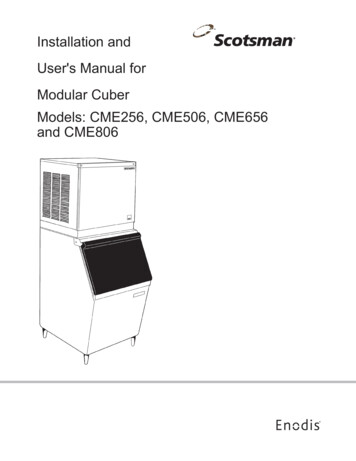
SIDE VIEWWARNINGExcessive Weight HazardUse two or more people to move and install ice maker.AB3⁵ ₈"(9.2 cm)1" (2.54 cm)C23"(58.4 cm)D2" - 1¹ ₂"(5 cm - 3.8 cm)A. Drain hoseB. 1" (2.54 cm) air gapC. PVC drain reducerD. Center of drain should be 23" (58.4 cm) from front of door,with or without the ³ ₄" (1.91 cm) panel on the door. Thedrain should also be centered from left to right (7⁵ ₁₆"[18.56 cm] from either side of the ice maker).Failure to do so can result in back or other injury.2. Style 1 - For gravity drain system, push the ice maker intoposition so that the ice maker drain tube is positioned overthe PVC drain reducer. See “Gravity Drain System” earlier inthis section. Style 2 - For drain pump system connect thedrain pump outlet hose to the drain. See “Drain PumpSystem” earlier in this section.3. Recheck the ice maker to be sure that it is level. See“Leveling.”4. If it is required by your local sanitation code, seal the cabinetto the floor with an approved caulking compound after allwater and electrical connections have been made.Ice Maker DoorTOOLS NEEDED:Gather the required tools and parts before starting installation. ⁵ ₁₆" wrench Flat putty knife ¹ ₄" wrench Phillips screwdriverDrain Pump System (on some models)Connect the ice maker drain to your drain in accordance with theInternational Plumbing Code and any local codes andordinances.NOTE: If the drain hose becomes twisted and water cannotdrain, your ice maker will not work.Hinge pin⁵ ₁₆" Hex-head hinge screwHandle screwEnd Cap screwConnecting the DrainAfter ensuring that the drain system is adequate, follow thesesteps to properly place the ice maker:WARNINGElectrical Shock HazardPlug into a grounded 3 prong outlet.Do not remove ground prong.Do not use an adapter.Remove Door1. Unplug ice maker or disconnect power.2. Remove the handle screws and handle (on some models).Keep the parts together and set them aside.3. Remove the hinge pin from the top hinge.4. Remove the door from the hinges and screw the top hinge pinback into the top hinge.5. Reverse the door end caps as follows: Remove both the screws and end caps (top and bottom). Move the top end cap diagonally to the opposite side'sbottom corner, keeping the straight side of the end capfacing the front of the ice maker Move the bottom end cap diagonally to the oppositeside's top corner, keeping the straight side of the end capfacing the front of the ice maker.Do not use an extension cord.Failure to follow these instructions can result in death,fire, or electrical shock.1. Plug ice maker into a grounded 3 prong outlet.66. Set the door aside.
Reverse HingesReverse Door Catch1. Unscrew and remove the top hinge. Replace the screws inthe empty hinge holes.2. Remove the screws from the bottom of the opposite side ofthe ice maker cabinet. Turn the top hinge upside down sothat the hinge pin points up. Place the hinge on the bottomopposite side of the ice maker and tighten screws.3. Remove the plastic hinge pin sleeve from the “old” bottomhinge and replace it on the new bottom hinge pin.4. Remove the “old” bottom hinge screws and hinge. Replacethe screws in the empty hinge holes.5. Remove the screws from the top of the opposite side of theice maker cabinet. Turn the hinge upside down so that thehinge pin points down. Place the hinge on the top oppositeside of the ice maker and tighten the screws.6. Remove the top hinge pin.1. Remove the hole plugs from the opposite side of the doorand set aside.2. Remove the screws from the magnetic door catch andreplace it on the opposite side of the door.3. Push the hole plugs into place on the opposite side of thedoor.WARNINGElectrical Shock HazardReplace DoorPlug into a grounded 3 prong outlet.1. Place plastic hinge pin sleeve in the top hinge hole on thedoor. Align the door with the top hinge hole and replace thetop hinge pin.2. Replace the handle and handle screws.Do not remove ground prong.Top HingeFailure to follow these instructions can result in death,fire, or electrical shock.Do not use an adapter.Do not use an extension cord.A4. Plug in ice maker or reconnect power.BNormal SoundsCYour new ice maker may make sounds that are not familiar toyou. Because the sounds are new to you, you might beconcerned about them. Most of the new sounds are normal. Hardsurfaces such as floors, walls and cabinets can make the soundsseem louder than they actually are. The following describes thekinds of sounds that might be new to you and what may bemaking them. You will hear a buzzing sound when the water valve opens tofill the water reservoir for each cycle.DA. Hinge pinB. Hinge pin sleeveC. HingeD. Hex-head hinge screw Rattling noises may come from the flow of the refrigerant orthe water line. Items stored on top of the ice maker can alsomake noises. The high-efficiency compressor may make a pulsating or highpitched sound. Water running over the evaporator plate may make asplashing sound. Water running from the evaporator plate to the water reservoirmay make a splashing sound. As each cycle ends, you may hear a gurgling sound due tothe refrigerant flowing in your ice maker.C You may hear air being forced over the condenser by thecondenser fan.D During the harvest cycle, you may hear a “thud” when the icesheet slides from the evaporator onto the cutter grid. When you first start the ice maker, you may hear waterrunning continuously. The ice maker is programmed to run arinse cycle before it begins to make ice.Bottom HingeABA. Hex-head hinge screwB. Hinge pin sleeveC. HingeD. Hinge pin7
ICE MAKER USEUsing the Controls1. To start the normal ice making cycle, select ON.2. To stop ice maker operation, select OFF.How Your Ice Maker WorksWhen you first start your ice maker, the water pan will fill and thesystem will rinse itself before starting to make ice. The rinsingprocess takes about 5 minutes.Under normal operating conditions, the ice maker will cycle atpreset temperatures. The ice level sensor located in the icestorage bin will monitor the ice levels.IMPORTANT: If the water supply to the ice maker is turned off, be sure toset the ice maker control to OFF. The ice maker is designed to make clear ice from the majorityof water sources on a daily basis. If your results areunsatisfactory, your water may need to be filtered or treated.The Ice Making Process1. Water is constantly circulated over a freezing plate. As thewater freezes into ice, the minerals in the water are rejected.This produces a sheet of ice with a low mineral content.NOTE: Pressing the ON/OFF switch does not shut off power tothe ice maker. Allow 24 hours to produce the first batch of ice. Discardthe first batch produced.Off LightThe off light blinks when service is needed. If the off light starts toblink, turn the ice maker off and back on. If the off light continuesto blink, call for service.Cleaning Needed Status LightThe Cleaning Needed Status light will help you know when it istime to clean your ice maker. The light will change from green toyellow. This tells you it is almost time to clean your ice maker. It isrecommended that you clean the ice maker when the status lightchanges to red OR ice production decreases significantly. Toclean your ice maker, see “Ice Maker System.”ICE MAKER CARE2. When the desired thickness is reached, the ice sheet isreleased and slides onto a cutter grid. The grid divides thesheet into individual cubes.CleaningThe ice making system and the air cooled condenser need to becleaned regularly for the ice maker to operate at peak efficiencyand to avoid premature failure of system components. See the“Ice Maker System” and the “Condenser” sections.Exterior Surfaces3. The water containing the rejected minerals is drained aftereach freezing cycle.4. Fresh water enters the machine for the next ice making cycle.5. Cubes fall into the storage bin. When the bin is full, the icemaker shuts off automatically and restarts when more ice isneeded. The ice bin is not refrigerated, and some melting willoccur. The amount of melting varies with room temperature.Wash the exterior enamel surfaces and gaskets with warm waterand mild soap or detergent. Wipe and dry. Regular use of a goodhousehold appliance cleaner and wax will help protect the finish.Do not use abrasive cleaners on enamel surfaces as they mayscratch the finish.For products with a stainless steel exterior, use a clean sponge orsoft cloth and a mild detergent in warm water. Do not useabrasive or harsh cleaners. Do not use chlorine bleach on thestainless steel surfaces.Ice Maker SystemNOTE: As the room and water temperatures vary, so will theamount of ice produced and stored. This means that higheroperating temperatures result in reduced ice production.8Minerals that are removed from water during the freezing cyclewill eventually form a hard scaly deposit in the water system.Cleaning the system regularly helps remove the mineral scalebuildup. How often you need to clean the system depends uponhow hard your water is. With hard water of 15 to 20 grains/gal.(4 to 5 grains/liter), you may need to clean the system as often asevery 6 months.NOTE: Use one 16 oz (473 mL) bottle of approved ice makercleaner. To order, call 1-800-442-9991 and ask for Part Number4396808. In Canada, call 1-800-807-6777.1. Push the selector switch to OFF.
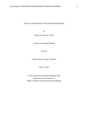
2. Wait 5 to 10 minutes for the ice to fall into the storage bin.Remove all ice from the storage bin.3. Unscrew the drain cap from the bottom of the water panlocated inside the storage bin as shown. Allow the water todrain completely.4. Replace the drain cap securely on the water pan. If the draincap is loose, water will empty from the water pan and you willhave either thin ice or no ice.5. Read and follow all handling information on the cleaner bottlebefore completing the steps below. Use one 16 oz (473 mL)bottle of approved ice maker cleaner.6. Pour one bottle of solution into the water pan. Fill the bottletwice with tap water and pour it into the water pan.2. Remove the two screws in the lower access panel and thetwo screws from the base grille area of the front panelsupport. Pull forward to remove the lower access panel.3. Pull the bottom forward and then pull down to remove thelower access panel.4. Remove dirt and lint from the condenser fins and the unitcompartment with a brush attachment on a vacuum cleaner.ABBCA. Water panB. Water pan thumb screwsC. Drain cap7. Press and hold the CLEAN button. See “Using the Controls.”The light will blink, indicating that the cleaning cycle is inprocess. When the indicator light turns green (approximately70 minutes), the cleaning cycle is complete. During thecleaning cycle, the system will both clean and rinse itself.8. After the cleaning cycle is complete, remove the drain capfrom the water pan. Look for any cleaning solution left in thewater pan. If cleaning solution drains from the water pan, youshould run the clean cycle again. Be sure to replace the draincap securely on the water pan. If the drain cap is loose, waterwill empty from the water pan and you will have either thin iceor no ice.NOTE: Severe scale buildup may require repeated cleaning witha fresh quantity of cleaning solution.9. Push the selector switch to ON to resume ice production.5. Replace the lower access panel using the four screws.6. Plug in ice maker or reconnect power.Interior Components1. Unplug ice maker or disconnect power.2. Open the storage bin door and remove any ice that is in thebin.3. Remove the drain cap from the water pan and drainthoroughly. Replace the drain cap securely on the water pan.If the drain cap is loose, water will empty from the water pan,and you will have either thin ice or no ice.4. Remove the two screws that hold the cutter grid cover inplace and remove the cutter grid cover.5. Unplug the wiring harness from the left side of the cutter grid.ACondenserBA dirty or clogged condenser: Obstructs proper airflow. Reduces ice making capacity. Causes higher than recommended operating temperatureswhich may lead to component failure.WARNINGA. Cutter grid coverB. Screws6. Unplug the ice level sensor from the right side of the cuttergrid. Pull the ice level sensor down and forward away fromthe cutter grid.7. Remove the right-hand and left-hand screws. Lift the cuttergrid up and out.NOTE: Make sure the plastic spacer from the right-hand sideof the cutter grid bracket stays with the cutter grid.DElectrical Shock HazardABCDisconnect power before cleaning.EFReplace all parts and panels before operating.Failure to do so can result in death or electrical shock.A. Cutter grid harnessB. ScrewC. Cutter gridD. Ice level sensor harnessE. Plastic spacerF. Screw1. Unplug ice maker or disconnect power.9
8. Remove the two thumb screws that hold the water pan inplace. Push down with one hand on the front of the pan whilepulling forward on the bottom back side.Vacation and Moving CareWARNINGABBElectrical Shock HazardCDisconnect power before servicing.A. Water panB. Water pan thumb screwsC. Drain capReplace all parts and panels before operating.9. Remove, clean and replace the ice scoop and ice scoopholder. After removing the ice scoop, remove the holder byremoving the two thumb screws. Wash the ice scoop holder along with the other interiorcomponents using the following instructions. Replace the ice scoop holder by replacing the thumbscrews.Failure to do so can result in death or electrical shock.To shut down the ice maker:1.2.3.4.Unplug ice maker or disconnect power.Remove all ice from storage bin.Shut off the water supply.Remove the two screws in the lower access panel and thetwo screws from the base grille area of the front panelsupport. Pull forward to remove the lower access panel.ABA. Thumb screwB. Ice scoop holder10. Wash the interior components (cutter grid, exterior of hoses,and water pan) and the storage bin, door gasket, ice scoop,and ice scoop holder with mild soap or detergent and warmwater. Rinse in clean water. Then clean the same parts with asolution of 1 tbs (15 mL) of household bleach in 1 gal. (3.8 L)warm water. Rinse again thoroughly in clean water.NOTE: Do not remove hoses. Do not wash plastic parts indishwasher. They cannot withstand temperatures above145 F (63 C).11. Replace water pan by pushing back on the bottom with onehand while pushing up and back on the top. Secure the waterpan by replacing both screws.12. Check the following: Drain cap from the water pan is securely in place. If thedrain cap is loose, water will empty from the water pan,and you will have either thin ice or no ice. Hose from water pan is inserted into storage bin drainopening.13. Slide the cutter grid back into place and secure it byreplacing the right-hand screw and plastic spacer. Thentighten the left-hand screw. Reconnect the cutter gridharness and the ice level sensor harness.14. Replace the cutter grid cover and the two screws.15. Plug in ice maker or reconnect power.105. Disconnect the inlet and outlet lines to water valve. Allowthese lines to drain and then re
(6.35 mm) saddle-type shutoff valve, a union, and copper tubing. Before purchasing, make sure a saddle-type valve complies with your local plumbing codes. Do not use a piercing-type or ³ ₁₆" (4.76 mm) saddle valve which reduces water flow and clogs more easily. Connecting the water line 1. Turn off main water supply. Turn on nearest .