Transcription
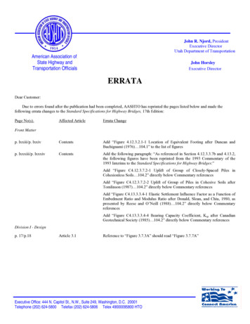
John R. Njord, PresidentExecutive DirectorUtah Department of TransportationAmerican Association ofState Highway andTransportation OfficialsJohn HorsleyExecutive DirectorERRATADear Customer:Due to errors found after the publication had been completed, AASHTO has reprinted the pages listed below and made thefollowing errata changes to the Standard Specifications for Highway Bridges, 17th Edition:Page No(s).Affected ArticleErrata Changep. lxxiii/p. lxxivContentsAdd “Figure 4.12.3.2.1-1 Location of Equivalent Footing after Duncan andBuchignami (1976) 104.1” to the list of figuresp. lxxxiii/p. lxxxivContentsAdd the following paragraph: “As referenced in Section 4.12.3.3.7b and 4.13.2,the following figures have been reprinted from the 1993 Commentary of the1993 Interims to the Standard Specifications for Highway Bridges:”Front MatterAdd “Figure C4.12.3.7.2-1 Uplift of Group of Closely-Spaced Piles inCohesionless Soils 104.2” directly below Commentary referencesAdd “Figure C4.12.3.7.2-2 Uplift of Group of Piles in Cohesive Soils afterTomlinson (1987) 104.2” directly below Commentary referencesAdd “Figure C4.13.3.3.4-1 Elastic Settlement Influence Factor as a Function ofEmbedment Ratio and Modulus Ratio after Donald, Sloan, and Chiu, 1980, aspresented by Reese and O’Neill (1988) 104.2” directly below CommentaryreferencesAdd “Figure C4.13.3.3.4-4 Bearing Capacity Coefficient, Ksp after CanadianGeotechnical Society (1985) 104.2” directly below Commentary referencesDivision I - Designp. 17/p.18Article 3.1Reference to “Figure 3.7.3A” should read “Figure 3.7.7A”Executive Office: 444 N. Capitol St., N.W., Suite 249, Washington, D.C. 20001Telephone (202) 624-5800 Telefax (202) 624-5806 Telex 49000095800 HTO
Page No(s).Affected ArticleErrata Changep. 39/p. 40Article 3.26.1.1Reference to “Article 20.19.1” should read “Article 16.3.14”p. 95/p. 96Article 4.11.2Remove the letter “C” from the following references: “ArticleC4.10.4” and “Article C4.11.4.1.1”p. 115/p. 116Article 5.2.2.4Reference to “1996 Commentary, Division 1A, Article 6, inparticular Equation C6-10 of these specifications” should read“AASHTO LRFD Bridge Design Specifications, 2nd Edition”p. 157/p. 158Article 5.8.7.1Reference to “Article 8.5.4.2” should read “Article 5.8.4.2”p. 239/p. 240Article 9.20.3.2Add missing square root symbol to “ 4 f c′b′ d ” so that it readsf c′ b′ d ”“4p. 253/p. 254Article 10.1.1Reference to “Article 10.38.17” for notation Fv should read“Article 10.38.1.7”p. 255/p. 256Article 10.1.1Reference to “Article 10.53.1.4” for notation Vu should read“Article 10.53.3”p. 289/p. 290Article 10.32.1In Table 10.32.1A, ““p. 339/p. 340Article 12.1.2135,008,740( KL / r )2135,000,740( KL / r )2” should read”Remove the following: “Cdl dead load adjustment coefficient(Article 12.8.4.3.2)”Reference to “Article 12.8.4.3.3” for Md should read “Article12.8.4.3.1”Reference to “Article 12.8.4.3.3” for M12.8.4.3.2”should read “ArticleReference to “Articles 12.3.1 and 12.3.3” for φ should read“Articles 12.3.1, 12.3.3, 12.5.3.1, 12.6.1.3, and 12.8.4.2”p. 343/p. 344Article 12.4.1.5Reference to “Article 23.10–Division II” should read“Division II, Article 26.6”p. 355/p. 356Article 12.8.4.3Three references to “Table 12.8.4D” should read “Table12.8.4B”Article 12.8.4.3.1Add “factored” in first paragraph before “crown and haunchdead load moments”Two references to “MDL” should read “Md ”Add “ ( Dead load, load factor ) ” to end of Equation 12-12Reference to “nominal” for Md should read “factored”Article 12.8.4.3.2HB-17-E3Add “factored” in first paragraph before “crown and haunchlive load moments”2
Page No(s).Affected ArticleErrata Changep. 355/p. 356Article 12.8.4.3.2Two references to “MLL” should read “M”Add parentheses around “C K1S/K2” and“ ( Live load, load factor ) ” to end of Equation 12-13Reference to “nominal” for Mshould read “factored”Article 12.8.4.3.3Add “ φ ” to beginning of Equations 12-19 and 12-20Article 12.8.4.33Delete “Cdl” and “Cll” from Equation 12-19Delete “Cdl” and “Cll” from Equation 12-20Article 12.8.5Reference to “Articles 23.3.1.4” should read “Division II,”p. 395/p. 396Article 14.6.5.2Reference to “Figure 14.6.5.2-2” should read “Figure14.6.5.2-1”p. 467/p. 468Article 7.3.1Reference to “Figure 5” should read “Figure 3.10”p. 509/p. 510Article 6.4.3Reference to “Article 10.3.1.4.3, ‘Anchorage Devices withDistribution Plates.’” should read “Division I, Article 9.21.7.2,‘Bearing Strength.’ ”p. 561/p. 562Article 10.10.2Reference to “Article 10.5.1.4” should read “Article 10.5.1”p. 579/p. 580Article 11.5.6.4.3Reference to “7/8 inch” should read “7/8”; the last bulletshould be a new paragraph, not a bullet.p. 631/p. 632Article 18.9.1Reference to “Article 18.4.10” should read “Article 18.4.9”p. 665/p. 666Article 26.5.4.1Reference to “Figure 26.5.1D” should read “Figure 26.5.2D”p. 687/p. 688Article 30.1.1Reference to “Division I, Section 18” should read “Division I,Section 17”Division II – ConstructionThe following new pages have been added:p. 104.1/p. 104.2Add Figure 4.12.3.2.1-1 Location of Equivalent Footing afterDuncan and Buchignami (1976) to p. 104.1Add the following paragraph: “As referenced in Section4.12.3.3.7b and 4.13.2, the following figures have beenreprinted from the 1993 Commentary of the 1993 Interims tothe Standard Specifications for Highway Bridges:” to p. 104.2Add Figure C4.12.3.7.2-1 Uplift of Group of Closely-SpacedPiles in Cohesionless Soils to p. 104.2Add Figure C4.12.3.7.2-2 Uplift of Group of Piles in CohesiveSoils after Tomlinson (1987) to p. 104.2HB-17-E33
p. 104.1/p. 104.2Add Figure C4.13.3.3.4-1 Elastic Settlement Influence Factoras a Function of Embedment Ratio and Modulus Ratio afterDonald, Sloan, and Chiu, 1980, as presented by Reese andO’Neill (1988) to p. 104.2Add Figure C4.13.3.3.4-4 Bearing Capacity Coefficient, Kspafter Canadian Geotechnical Society (1985) to p. 104.2Please substitute the original pages of text with the enclosed pages. We apologize for any inconvenience thismay have caused.AASHTO Publications StaffJune 2004HB-17-E34
FiguresCONTENTSFigure 3.7.6BFigure 3.7.7ALane Loading . . . . . . . . . . . . . . . . . . . . . . . . . . . . . . . . . . . . . . .23Standard HS Trucks . . . . . . . . . . . . . . . . . . . . . . . . . . . . . . . . . .24SECTION 4—FOUNDATIONSFigure 4.4.3AFigure 4.4.7.1.1.1AFigure 4.4.7.1.1.1BFigure 4.4.7.1.1.1CFigure 4.4.7.1.1.4AFigure 4.4.7.1.1.4BFigure 4.4.7.1.1.6AFigure 4.4.7.1.1.7AFigure 4.4.7.1.1.7BFigure 4.4.7.1.1.8AFigure 4.4.7.2.1AFigure 4.4.7.2.3AFigure 4.4.7.2.3BFigure 4.4.7.2.3CFigure 4.4.7.2.3DFigure 4.4.8.1.1AFigure 4.4.8.2.2AFigure 4.5.4AFigure 4.6.3AFigure 4.6.5.1.1AFigure 4.6.5.3.1AFigure 4.6.5.5.1.1AFigure 4.6.5.5.1.1BFigure 4.6.5.5.1.2ADesign Terminology for Spread Footing Foundations . . . . . . .48Definition Sketch for Loading and Dimensionsfor Footings Subjected to Eccentric or Inclined Loads,Modified after EPRI (1983) . . . . . . . . . . . . . . . . . . . . . . . . . .52Contact Pressure for Footing Loaded EccentricallyAbout One Axis . . . . . . . . . . . . . . . . . . . . . . . . . . . . . . . . . . . .52Contact Pressure for Footing Loaded EccentricallyAbout Two Axes, Modified after AREA (1980) . . . . . . . . . .53Modified Bearing Capacity Factors for Footingson Sloping Ground, Modified after Meyerhof (1957) . . . . .54Modified Bearing Capacity Factors for Footing AdjacentSloping Ground, Modified after Meyerhof (1957) . . . . . . . . .54Definition Sketch for Influence of Ground Water Tableon Bearing Capacity . . . . . . . . . . . . . . . . . . . . . . . . . . . . . . . .55Typical Two-Layer Soil Profiles . . . . . . . . . . . . . . . . . . . . . . . . .56Modified Bearing Capacity Factor for Two-Layer CohesiveSoil with Softer Soil Overlying Stiffer Soil, EPRI (1983) . .56Definition Sketch for Footing Base Inclination . . . . . . . . . . . .57Boussinesg Vertical Stress Contours for Continuousand Square Footings, Modified after Sowers (1979) . . . . . .58Typical Consolidation Compression Curvefor Overconsolidated Soil—Void RatioVersus Vertical Effective Stress, EPRI (1983) . . . . . . . . . . .60Typical Consolidation Compression Curvefor Overconsolidated Soil—Void StrainVersus Vertical Effective Stress . . . . . . . . . . . . . . . . . . . . . . .60Reduction Factor to Account for Effects of ThreeDimensional Consolidation Settlement, EPRI (1983) . . . . .60Percentage of Consolidation as a Function of TimeFactor, T, EPRI (1983) . . . . . . . . . . . . . . . . . . . . . . . . . . . . . .61Allowable Contact Stress for Footings on Rock with TightDiscontinuities, Peck, et al. (1974) . . . . . . . . . . . . . . . . . . . . .62Relationship Between Elastic Modulus and UniaxialCompressive Strength for Intact Rock, Modifiedafter Deere (1968) . . . . . . . . . . . . . . . . . . . . . . . . . . . . . . . . . .66Design Terminology for Driven Pile Foundations . . . . . . . . . .71Design Terminology for Drilled Shaft Foundations . . . . . . . . .81Identification of Portions of Drilled Shafts Neglectedfor Estimation of Drilled Shaft Side Resistancein Cohesive Soil, Reese and O’Neill (1988) . . . . . . . . . . . . . .82Procedure for Estimating Average Unit Shear for SmoothWall Rock-Socketed Shafts, Horvath et al. (1983) . . . . . . . .85Load Transfer in Side Resistance Versus Settlement DrilledShafts in Cohesive Soil, after Reese and O’Neill (1988) . . .87Load Transfer in Tip Bearing Settlement Drilled Shaftsin Cohesive Soil, after Reese and O’Neill (1988) . . . . . . . . .87Load Transfer in Side Resistance Versus Settlement Drilled Shaftsin Cohesionless Soil, after Reese and O’Neill (1988) . . . . . .88lxxiii
lxxivCONTENTSFigure 4.6.5.5.1.2BFigure 4.6.5.5.2AFigure 4.6.5.5.2BFigure 4.12.3.2.1-1Figure 5.2AFigure 5.2BFigure 5.2CFigure 5.5.1AFigure 5.5.2AFigure 5.5.2BFigure 5.5.2CFigure 5.5.2DFigure 5.5.5AFigure 5.6.2AFigure 5.6.2BFigure 5.6.2CFigure 5.6.2DFigure 5.7.1AFigure 5.7.2AFigure 5.7.2BFigure 5.8.1AFigure 5.8.2AFigure 5.8.2BFigure 5.8.2CFigure 5.8.2DFigure 5.8.3ALoad Transfer in Tip Bearing Versus Settlement Drilled Shaftsin Cohesionless Soil, after Reese and O’Neill (1988) . . . . . .88Influence Coefficient for Elastic Settlement of Rock-SocketedDrilled Shafts, Modified after Pells and Turner (1979) . . . .89Influence Coefficient for Elastic Uplift Displacement ofRock-Socketed Drilled Shafts, Modified after Pells andTurner (1979) . . . . . . . . . . . . . . . . . . . . . . . . . . . . . . . . . . . . .89Location of Equivalent Footing after Duncan and Buchignami(1976) . . . . . . . . . . . . . . . . . . . . . . . . . . . . . . . . . . . . . . . . .104.1Typical Mechanically Stabilized Earth Gravity Walls . . . . .112Typical Prefabricated Modular Gravity Walls . . . . . . . . . . .113Typical Rigid Gravity, Semi-Gravity Cantilever, NongravityCantilever, and Anchored Walls . . . . . . . . . . . . . . . . . . . . .114Terms Used in Design of Rigid Gravity and Semi-GravityRetaining Walls . . . . . . . . . . . . . . . . . . . . . . . . . . . . . . . . . . .121Computational Procedures for Active Earth Pressures(Coulomb Analysis) . . . . . . . . . . . . . . . . . . . . . . . . . . . . . . .122Procedure to Determine Lateral Pressure Due to Point andLine Loads, Modified after Terzaghi (1954) . . . . . . . . . . . .123Computational Procedures for Passive Earth Pressures for Sloping Wall with Horizontal Backfill (Caquot and Kerisel Analysis), Modified after U.S. Department of Navy (1982) . . . . . .124Computational Procedures for Passive Earth Pressures for Vertical Wall with Sloping Backfill (Caquot and Kerisel Analysis),Modified after U.S. Department of Navy (1982) . . . . . . . . .125Design Criteria for Rigid Retaining Walls,(Coulomb Analysis) . . . . . . . . . . . . . . . . . . . . . . . . . . . . . . .127Simplified Earth Pressure Distributions for PermanentFlexible Cantilevered Walls with Discrete Vertical WallElements . . . . . . . . . . . . . . . . . . . . . . . . . . . . . . . . . . . . . . . .129Simplified Earth Pressure Distributions and DesignProcedures for Permanent Flexible Cantilevered Wallswith Continuous Vertical Wall Elements, Modified afterTeng (1962) . . . . . . . . . . . . . . . . . . . . . . . . . . . . . . . . . . . . . .130Simplified Earth Pressure Distributions for TemporaryFlexible Cantilevered Walls with Discrete Vertical WallElements . . . . . . . . . . . . . . . . . . . . . . . . . . . . . . . . . . . . . . . .130Simplified Earth Pressure Distributions for TemporaryFlexible Cantilevered Walls with Continuous VerticalWall Elements, Modified after Teng (1962) . . . . . . . . . . . .131Typical Terms Used in Flexible Anchored Wall Design . . . .133Guidelines for Estimating Earth Pressure on Walls withTwo or More Levels of Anchors Constructed from the TopDown, Modified after Terzaghi and Peck (1967) . . . . . . . .134Settlement Profiles Behind Braced or Anchored Walls,Modified after Clough and O’Rourke (1990) . . . . . . . . . . .135MSE Wall Element Dimensions Needed for Design . . . . . . .139External Stability for Wall with Horizontal Backslopeand Traffic Surcharge . . . . . . . . . . . . . . . . . . . . . . . . . . . . .140External Stability for Wall with Sloping Backslope . . . . . . .141External Stability for Wall with Broken Backslope . . . . . . .142Overall and Compound Stability of Complex MSEWall Systems . . . . . . . . . . . . . . . . . . . . . . . . . . . . . . . . . . . . .143Calculation of Vertical Stress for Bearing CapacityCalculations (for Horizontal Backslope Condition) . . . . .144Figures
TablesCONTENTSSECTION 11—STEEL STRUCTURESTable 11.4.3.3.2Table 11.5ATable 11.5BTable 11.5CMinimum Cold-Bending Radii . . . . . . . . . . . . . . . . . . . . . . . .571Required Fastener Tension Minimum Bolt Tensionin Pounds . . . . . . . . . . . . . . . . . . . . . . . . . . . . . . . . . . . . . . . .578Nut Rotation from the Snug-Tight Condition Geometryof Outer Faces of Bolted Parts . . . . . . . . . . . . . . . . . . . . . . .579Untitled . . . . . . . . . . .
HB-17-E3 3 . p. 104.1/p. 104.2 Add Figure C4.13.3.3.4-1 Elastic Settlement Influence Factor as a Function of Embedment Ratio and Modulus Ratio after Donald, Sloan, and Chiu, 1980, as presented by Reese and O’Neill (1988) to p. 104.2 Add Figure C4.13.3.3.4-4 Bearing Capacity Coefficient, Ksp after Canadian Geotechnical Society (1985) to p. 104.2 Please substitute the original pages of text .

