Transcription
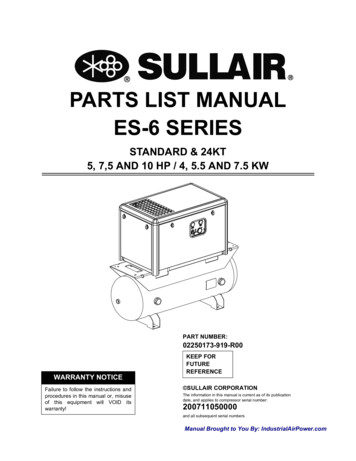
PARTS LIST MANUALES-6 SERIESSTANDARD & 24KT5, 7,5 AND 10 HP / 4, 5.5 AND 7.5 KWPART NUMBER:02250173-919-R00WARRANTY NOTICEFailure to follow the instructions andprocedures in this manual or, misuseof this equipment will VOID itswarranty!KEEP FORFUTUREREFERENCE SULLAIR CORPORATIONThe information in this manual is current as of its publicationdate, and applies to compressor serial number:200711050000and all subsequent serial numbersManual Brought to You By: IndustrialAirPower.com
Sullair Corporation3700 E. Michigan Blvd.Michigan City, IN 46360Attn: Service Training Department.- Or Write -1-888-SULLAIR or219-879-5451 (ext. 5623)www.sullair.comSullair Customer Care Training DepartmentFor detailed course outlines, schedule, and cost information contact:Instruction includes training on the function and installation of Sullair service parts, troubleshooting common faults andmalfunctions, and actual equipment operation. These seminars are recommended for maintenance, contractormaintenance, and service personnel.Sullair Air Care Seminars are courses that provide hands-on instruction for the proper operation, maintenance, andservicing of Sullair products. Individual seminars on Industrial compressors and compressor electrical systems are offeredat regular intervals throughout the year at Sullair’s corporate headquarters training facility located at Michigan City, Indiana.AIR CARE SEMINAR TRAINING
62830323436CONTROL BOX - WYE-DELTA DECALS, ETC.CONTROL BOX - WYE-DELTACONTROL BOX - STANDARDRECEIVER TANK - ENCLOSED WITHDRYERRECEIVER TANK - OPEN WITHDRYERRECEIVER TANK - ENCLOSEDRECEIVER TANK - OPENINLET CONTROLCOMPRESSOR SYSTEMCOMPRESSOR COOLING SYSTEMMOTOR, HOUSING AND PARTSSEAL AND DRIVE GEARINLET FILTERFLUID MANAGEMENT SYSTEMFRAME AND MOUNTING - TANKMOUNTED ENCLOSUREFRAME AND MOUNTING - STANDARDAND ENCLOSUREFRAME AND MOUNTING - OPENMAINTENANCE PARTS LISTPROCEDURE FOR ORDERING 271.261.251.241.231.203846SECTIONPAGETABLE OF CONTENTSDRYER OPTION - SCF125/SRS75(SRS-24)DRYER OPTION - SCF65/SRS50(SRS-18)DRYER OPTION - SCF40/SRS35(SRS-12)DRYER OPTION - SCF40/SRS25(SRS-9)DECAL LOCATIONS - ES-6 OPENTANK-MOUNTEDDECAL LOCATIONS - ES-6 ENCLOSEDTANK-MOUNTEDDECAL LOCATIONS - ES-6 ENCLOSEDSTANDARDDECAL LOCATIONS - ES-6 OPENSTANDARDDECAL GROUPENCLOSUREDESCRIPTION
ES-6 SERIES PART LIST MANUALFigure 1-1 Serial Plate / Serial Number Location1-888-SULLAIR (785-5247)219-874-1835CUSTOMER CARE for PARTS and SERVICESullair Road, No. 13700 East Michigan BoulevardMichigan City, Indiana 46360 U.S.Awww.sullair.comTelephone: 1-800-SULLAIR (U.S.A. only)Fax: 219-874-1273Chiwan, ShekuoShenzhen, Guangdong PRV.PRC POST CODE 518068Telephone: 755-6851686Fax: 755-6853473www.sullair-asia.comSULLAIR EUROPE, S.A.Zone Des Granges BP 8242602 Montbrison, FranceTelephone: 33-477968470Fax: 33-477968499www.sullaireurope.comSULLAIR ASIA, LTD.SULLAIR CORPORATIONHallam, Victoria 3803AustrailiaTelephone: 61-3-9796-4000Fax: ss HighwayCHAMPION COMPRESSORS, LTD.1The genuine Sullair service parts listed meet or exceed the demands of this compressor. Use of replacement parts other than those approved bySullair Corporation may lead to hazardous conditions over which Sullair Corporation has no control. Such conditions include, but are not limited to,bodily injury and compressor failure.When ordering parts always indicate the Serial Number of the compressor. This can be obtained from the Bill of Lading for the compressor or fromthe Serial Number Plate located on the compressor. See Figure 1-1 Serial Plate / Serial Number Location.Parts should be ordered from the nearest Sullair Representative or the Representative from whom the compressor was purchased. If for any reasonparts cannot be obtained in this manner, contact the factory directly at the address, phone numbers or fax numbers below.1.1 PROCEDURE FOR ORDERING PARTSSection 1 - ILLUSTRATION AND PARTS LIST
2KITSrepair kit for minimum pressure/check valve 604131replacement piston seal kit for air inlet control valvereplacement piston for inlet control valvereplacement washer for inlet control valverepair kit for ES-6 1/2" npt service connection 250026-066replacement kit for hoses srs 25-35replacement kit for hoses srs 50-75replacement for dryer pre-filter scf-40n/breplacement for dryer pre-filter scf-65n/breplacement for dryer pre-filter 250153-2918 910111213141516171819repair kit for thermostat actuator 250025-413NOTEContinued on page 3PLEASE NOTE: WHEN ORDERING PARTS, INDICATE SERIAL NUMBER OF COMPRESSORrepair kit for regulator valve 250017-280replacement coil for solenoid valve 02250125-655repair kit for solenoid valve 02250125-65511250028-03602250160-743repair kit, shaft seal installationrepair kit for motor shaft seal 02250100-823filter, clean air inlet option es6replacement element kit for air filter 02250111-680replacement element kit for air/fluid separator 250025-264replacement element kit for fluid filter 250026-982DESCRIPTIONSection 1 - ILLUSTRATION AND PARTS 28-0351250028-033251QTY250028-032ORDER PART NO.1ELEMENTSKEY NO.1.2 MAINTENANCE PARTS LISTES-6 SERIES PART LIST MANUAL
250022-66902250051-153250019-662212223fluid, Sullube (one gallon)fluid, Sullube (five gallons)fluid, 24 KT (five gallons)fluid, SRF 1/4000 (five gallons)-DESCRIPTION-QTY(I)(I)(I)(I)NOTEPLEASE NOTE: WHEN ORDERING PARTS, INDICATE SERIAL NUMBER OF COMPRESSORMixing of other lubricants within the compressorunit will void all warranties.CAUTION!3ES-6 SERIES PART LIST MANUAL(I) For proper amount of fluid fill, please consult Lubrication Guide in Section 3, Specifications in the User’s Manual.250009-396ORDER PART NO.20FLUIDKEY NO.1.2 MAINTENANCE PARTS LIST (CONTINUED)Section 1 - ILLUSTRATION AND PARTS LIST
402250170-709R001.3 FRAME AND MOUNTING - OPENES-6 SERIES PART LIST MANUALSection 1 - ILLUSTRATION AND PARTS LIST
08-02012345678910DESCRIPTION1 screw, hex serr washer m8 x 201 nut, serr flng m8 x 1.252 washer, lock ext tooth 1/44 washer, pl-b reg pltd 1/41 screw, hex ser washer 1/4-20 x 3/48 nut, hex f pltd 5/16-182 nut, hex f pltd 1/4-204 isolator, vibration 3/4" x 1-1/4" x 93#1 support, shipping es6 tm open1 wire, ground bond 12" 10 gaQTYPLEASE NOTE: WHEN ORDERING PARTS,INDICATE SERIAL NUMBER OF COMPRESSOR11various1 es6 unit(I) This part may vary per machine design. Consult factory withmachine serial number to determine the proper part number.PARTNO.KEYNO.1.3 FRAME AND MOUNTING - OPENSection 1 - ILLUSTRATION AND PARTS LIST(I)NOTE5ES-6 SERIES PART LIST MANUAL
602250170-710001.4 FRAME AND MOUNTING - STANDARD ENCLOSUREES-6 SERIES PART LIST MANUALSection 1 - ILLUSTRATION AND PARTS LIST
05012345678910111213141516A1 A2DESCRIPTION2 conn, 37 fl/mpt pltd 3/4 x 1/21 hose, 3/4 encl 7.5-10 hp es61 hose, 3/4 encl 5 hp es61 es6 unit6 screw, tf-hex m8 x 16 blk zinc1 screw, hex serr washer m8 x 161 nut, serr flng m8 x 1.256 washer, sealing m82 washer, lock ext tooth 1/44 washer, pl-b reg pltd 1/41 screw, hex ser washer 1/4-20 x 3/44 nut, hex f pltd 5/16-182 nut, hex f pltd 1/4-204 gasket, seal es6 encl vib mnt4 isolator, vibration 3/4" x 1-1/4" x 93#1 support, shipping es6 encl2 rail, encl bse es6 std1 frame, base pan es61 wire, ground bond 24" 10 gaQTYA3841500-0081 bulkhead, pipe 1/2” npt(I) This part may vary per machine design. Consult factory withmachine serial number to determine the proper part number.PARTNO.KEYNO.1.4 FRAME AND MOUNTING - STANDARD ENCLOSURESection 1 - ILLUSTRATION AND PARTS LIST(I)NOTEKEYNO.QTYDESCRIPTIONPLEASE NOTE: WHEN ORDERING PARTS,INDICATE SERIAL NUMBER OF COMPRESSORPARTNO.NOTE7ES-6 SERIES PART LIST MANUAL
802250170-712R001.5 FRAME AND MOUNTING - TANK-MOUNTED ENCLOSUREES-6 SERIES PART LIST MANUALSection 1 - ILLUSTRATION AND PARTS LIST
0172-677KEYNO.123456789101112131415161718A1 DESCRIPTION1 hose, 3/4 unit/tnk encl l/dr 801 hose, 3/4 unit/tnk encl w/dr 1201 hose, 3/4 unit/tnk encl w/dr 801 hose, 3/4 unit/tnk opn l/dr1 hose, 3/4 unit/tnk opn w/dr1 es6 unit6 screw, hex serr washer m8 x 251 screw, hex serr washer m8 x 168 nut, serr flng m8 x 1.256 washer, sealing m84 washer, lock ext tooth 1/48 washer, pl-b reg pltd 1/42 screw, hex ser washer 1/4-20 x 14 nut, hex f pltd 5/16-183 nut, hex f pltd 1/4-201 clamp, hose 7/8" i.d.4 gasket, seal es6 encl vib mnt4 isolator, vibration 3/4" x 1-1/4" x 93#1 support, shipping es6 encl1 frame, base pan es61 wire, ground bond 24" 10 ga1 wire, ground bond 12" 10 ga1 trim, clip-on grip 185-260duqQTY1.5 FRAME AND MOUNTING - TANK-MOUNTED ENCLOSURESection 1 - ILLUSTRATION AND PARTS LIST(I)NOTEPARTNO.QTYDESCRIPTIONPLEASE NOTE: WHEN ORDERING PARTS,INDICATE SERIAL NUMBER OF COMPRESSOR 02250172-678 1 hose, 3/4 unit/tnk encl l/dr 120(I) This part may vary per machine design. Consult factory withmachine serial number to determine the proper part number.KEYNO.NOTE9ES-6 SERIES PART LIST MANUAL
101.6 FLUID MANAGEMENT SYSTEMES-6 SERIES PART LIST MANUALSection 1 - ILLUSTRATION AND PARTS LIST
51617 DESCRIPTION12 capscrew, socket ISO4762 m 12 x80 (metric)12 capscrew, ferry hd 1/2"-13 x 3"1 actuator, thermostat1 piston, thermostat1 spring, compression1 pin, roll 1/4" x 1 1/2"1 guide, thermostat spring1 plug, thermostat 1 1/16"-121 glass, sight1 adapter, fluid filter1 element, fluid filter1 cap, separator element1 o-ring, 2 3/16" x 3/32"1 element, separator air/fluid1 o-ring, 1 7/16" x 1/16"1 housing, bell3 o-ring1 plug, hex head 1 1/16"-12 SAEQTY(II) For maintenance on air/fluid separator element no. 250025264, order repair kit no. 250028-033.181 decal, fluid(I) For replacement only.PARTNO.KEYNO.1.6 FLUID MANAGEMENT SYSTEMSection 1 - ILLUSTRATION AND PARTS EASE NOTE: WHEN ORDERING PARTS,INDICATE SERIAL NUMBER OF COMPRESSOR(V) Decal will vary with compressor fluid fill requirement. Factoryfill (Sullube) decal part no. is 02250069-389.(IV) For maintenance on thermostat actuator no. 250025-413,order repair kit no. 250028-036.(III) For maintenance on fluid filter element no. 250026-982, orderrepair kit no. 250028-032.KEYNO.11NOTEES-6 SERIES PART LIST MANUAL
121.7 INLET FILTERES-6 SERIES PART LIST 1 rod, threaded 1/4" x 7.25"1 plate, air filter base1 element, air filter1 hood, air filter1 washer, seal1 nut, wing 1/4"-201 filter, assemblyQTYPLEASE NOTE: WHEN ORDERING PARTS,INDICATE SERIAL NUMBER OF COMPRESSOR802250111-683 1 pre-filter, heavy duty(I) For maintenance on air filter assembly no. 02250111-679, orderrepair kit no. 02250111-804.PARTNO.KEYNO.1.7 INLET FILTER(I)NOTESection 1 - ILLUSTRATION AND PARTS LIST
PARTNO.250028-339499082-705consult factoryconsult 67DESCRIPTION1 seal, shaft Teflon/Viton1 sleeve, wear1 spacer, gear1 gear, drive1 gear, driven1 bearing, cylinder roll plain1 plate, inletQTY1.8 SEAL AND DRIVE GEAR1.8 SEAL AND DRIVE GEARSection 1 - ILLUSTRATION AND PARTS LIST(I)NOTEDESCRIPTION2 capscrew, ferry head 1/4" - 20 x 3/4"1 housing, shaft sealQTYPLEASE NOTE: WHEN ORDERING PARTS,INDICATE SERIAL NUMBER OF COMPRESSORNOTE: Requires special tooling for removal/installation.10826502-1501 o-ring, 2 7/8" x 3/32"(I) For maintenance on motor shaft seal no. 02250100-823, orderrepair kit no. TEES-6 SERIES PART LIST MANUAL
141.9 MOTOR, HOUSING AND PARTSES-6 SERIES PART LIST MANUALSection 1 - ILLUSTRATION AND PARTS LIST
4567891011121314 15161718DESCRIPTION2 capscrew, hex GR8 1/2"-13 x 1"2 washer, reg 1/2"2 plug, pipe hex soc 1/8" NPT1 switch, temperature 230 F NC1 valve, relief 1/2" 200# (13.8 bar)1 valve, relief 1/2" 175# (12.1 bar)1 cap, minimum pressure/check valve1 spring, minimum pressure/checkvalve1 o-ring, 3/32" x 3/4"1 piston, minimum pressure/checkvalve1 spring, minimum pressure/checkvalve1 stem, minimum pressure/checkvalve1 seat, minimum pressure/checkvalve1 washer, pl-b #81 screw, machine rd hd #8-32 x 1/2"1 group, minimum pressure valve1 capscrew, hex 5/16"-18 x 7/8"1 bail, lifting1 connector, tube-M 5/8" x 1/2"QTY1.9 MOTOR, HOUSING AND PARTSSection 1 - ILLUSTRATION AND PARTS LIST(I)NOTEDESCRIPTION1 connector, tube-M 1/2" x 1/2"1 base, compressorQTYPLEASE NOTE: WHEN ORDERING PARTS,INDICATE SERIAL NUMBER OF COMPRESSOR15NOTEA1: If the addition of fluid becomes frequent, a problem has developed. By removing lower plug, fluid may spill from hole; a shaft sealfailure may exist.(I) For maintenance on minimum pressure valve group no.604131, order repair kit no. -6 SERIES PART LIST MANUAL
161.10 COMPRESSOR COOLING SYSTEMES-6 SERIES PART LIST MANUALSection 1 - ILLUSTRATION AND PARTS LIST
034-535consult factory250028-964consult EYNO.1 23 4567891011121314151617181920DESCRIPTION1 tubing, fluid cooler out1 elbow, tube 7/8" x 1/2"2 connector, tube 1/2" x 3/4"1 tube, fluid cooler out es61 tubing, aftercooler in1 elbow, tube 5/8" x 7/8"2 capscrew, ferry hd 5/16"-18 x 2"2 washer, flat 5/16" x 1 1/4"1 cooler, fluid1 plate, cooler filler1 nut, hex 5/16"-188 insert, 1/4"-20 threaded blind1 ring, orifice1 screw, brass set1 fan, 12" dia1 guard, fan1 motor1 ring, aftrclr 180 frame1 ring, aftrclr 210 frame8 screw, hex serrated washer 1/4"-20x 1/2"1 duct, cooler motor 180 frame1 duct, cooler motor 210 frameQTY1.10 COMPRESSOR COOLING SYSTEMSection 1 - ILLUSTRATION AND PARTS LISTNOTEPARTNO.QTYDESCRIPTIONPLEASE NOTE: WHEN ORDERING PARTS,INDICATE SERIAL NUMBER OF COMPRESSORA4: Discharge airA3: From compressor (out) to aftercooler (in)A2: Oil cooler (out) to compressor (in)A1: To compressor drainKEYNO.17NOTEES-6 SERIES PART LIST MANUAL
181.11 COMPRESSOR SYSTEMES-6 SERIES PART LIST MANUALSection 1 - ILLUSTRATION AND PARTS LIST
TION1 valve, regulator1 nipple, pipe 1/4"NPT x close3 elbow, tube 90 M 1/4" x 1/4"1 hose, nylon 1/4"1 plate, inlet2 capscrew, ferry hd 3/8"-16 x 3 3/4"1 rotor, male "E" profile1 rotor, female "E" profile4 pin, dowel 3/8" x 1"2 washer, seal2 capscrew, ferry hd 5/16"-18 x 2 1/4"1 housing, stator2 capscrew, socket hd 1/4"-20 x 1/4"1 washer, metric elt sm 8 x 153 capscrew, ferry hd 5/16"-18 x 1"2 bearing, taper1 wavespring, male1 locknut, male M25 x 12 bearing, taper1 wavespring, female1 locknut, female M17 x 11 cover, outlet5 capscrew, ferry hd 1/4"-20 x 1 1/4"QTY1.11 COMPRESSOR SYSTEM 1Section 1 - ILLUSTRATION AND PARTS 8250041-9563435363738DESCRIPTION1 tee, tube1 conn, tube-m 1/2 X 3/8"1 screw, set cup 5/8"-11 x 1/2"1 valve, body thermostat1 fitting, separator fluid return1 tube, separator fluid return2 capscrew, ferry hd 5/16"-18 x 1 1/2"1 screw, machine flat head 1/4"-20 x1/2"1 retainer, inlet bearing1 bearing, needle roller steel1 orifice, gear spray (mounting location)1 bearing, cylinder roll plain1 plate, identification2 screw, drive rod plated #8 x 3/8"1 tee, tube 1/4"QTYPLEASE NOTE: WHEN ORDERING PARTS,INDICATE SERIAL NUMBER OF COMPRESSORContinued on page 21(II) For maintenance on thermostat, order repair kit no. 250028036.39250034-0011 base, compressor(I) For maintenance on pressure regulator valve no. 250017-280,order repair kit no. NOTEES-6 SERIES PART LIST MANUAL
201.11 COMPRESSOR SYSTEM (CONTINUED)ES-6 SERIES PART LIST MANUALSection 1 - ILLUSTRATION AND PARTS LIST
1 plug, pipe 3/8” 3000# stl plt1 tube, fluid drain es6 w/ encl1 valve, ball mini f x f 3/8” viton1 valve, ball 1/4"1 nipple, pipe 1/4" x 2 1/2"1 tee, pipe 1/4"2 capscrew, ferry hd 3/8"-16 x 3/4"PLEASE NOTE: WHEN ORDERING PARTS,INDICATE SERIAL NUMBER OF COMPRESSORA4: To “out” solenoid valveA3: To air inletA2: To pressure gaugeDESCRIPTION2 washer, reg 3/8"QTYA1: To “in” solenoid valvePARTNO.KEYNO.1.11 COMPRESSOR SYSTEM (CONTINUED)Section 1 - ILLUSTRATION AND PARTS LISTNOTE21ES-6 SERIES PART LIST MANUAL
221.12 INLET CONTROLES-6 SERIES PART LIST MANUALSection 1 - ILLUSTRATION AND PARTS LIST
29-8981234567891011121314DESCRIPTION1 cap, air intake1 spring, inlet control1 capscrew, #10-32 x 1/2" Nylok2 washer, Belleville spring1 seal, intake control piston1 piston, intake control valve1 elbow, 90 M 1/8"npt x 1/4" tubehose, nylon 1/4"1 housing, intake control1 head, intake control valve1 gasket, inlet valve1 retainer, intake control valve1 spring, intake check1 rod, intake control valveQTYPLEASE NOTE: WHEN ORDERING PARTS,INDICATE SERIAL NUMBER OF COMPRESSOR15836150-1371 ring, retaining internal 1 3/8"(I) For maintenance on inlet control valve, order replacement piston seal kit no. 02250045-287, and replacement piston no.02250044-811.PARTNO.KEYNO.1.12 INLET CONTROLSection 1 - ILLUSTRATION AND PARTS LIST(I)NOTE23ES-6 SERIES PART LIST MANUAL
2402250172-397R001.13 RECEIVER TANK - OPENES-6 SERIES PART LIST MANUALSection 1 - ILLUSTRATION AND PARTS LIST
1 23456789DESCRIPTION1 bushing, red hex pltd 1 1/4 x 3/41 nipple, pipe pltd 1/4 x 1 1/21 nipple, pipe pltd 1/4 x 11 elbow, pipe 90 deg plt 1/4"1 elbow, 37fl 90m 3/4 x 3/41 plug, pipe 1 1/4" 3000# stl1 valve, pressure relief 200 psig1 valve, ball 1/4" npt1 tank, assy es6 120 gal1 tank, assembly es6 80 galQTYPLEASE NOTE: WHEN ORDERING PARTS,INDICATE SERIAL NUMBER OF COMPRESSORA2: Tank drainA1: From unitPARTNO.KEYNO.1.13 RECEIVER TANK - OPENSection 1 - ILLUSTRATION AND PARTS LISTNOTE25ES-6 SERIES PART LIST MANUAL
2602250172-395R001.14 RECEIVER TANK - ENCLOSEDES-6 SERIES PART LIST MANUALSection 1 - ILLUSTRATION AND PARTS LIST
1 23456789DESCRIPTION2 bushing, red hex pltd 1 1/4 x 3/41 nipple, pipe pltd 1/4 x 1 1/21 nipple, pipe pltd 1/4 x 11 elbow, pipe 90 deg plt 1/4"2 elbow, 37fl 90m 3/4 x 3/41 plug, pipe 1 1/4" 3000# stl1 valve, pressure relief 200 psig1 valve, ball 1/4" npt1 tank, assembly es6 120 gal1 tank, assembly es6 80 galQTYPLEASE NOTE: WHEN ORDERING PARTS,INDICATE SERIAL NUMBER OF COMPRESSORA2: Tank drainA1: From unitPARTNO.KEYNO.1.14 RECEIVER TANK - ENCLOSED Section 1 - ILLUSTRATION AND PARTS LISTNOTE27ES-6 SERIES PART LIST MANUAL
2802250172-393R001.15 RECEIVER TANK - OPEN WITH DRYERES-6 SERIES PART LIST MANUALSection 1 - ILLUSTRATION AND PARTS LIST
1 234567892 bushing, red hex pltd 1 1/4 x 3/41 plug, pipe 1 1/4" 3000# stl plt1 nipple, pipe pltd 1/4 x 1 1/21 nipple, pipe pltd 1/4 x 11 elbow, pipe 90 deg plt 1/4"2 elbow, 37fl 90m 3/4 x 3/41 valve, pressure relief 200 psig1 valve, ball 1/4" npt1 tank, assembly es6 120 galPLEASE NOTE: WHEN ORDERING PARTS,INDICATE SERIAL NUMBER OF COMPRESSORA3: Tank drainDESCRIPTION1 tank, assembly es6 80 galQTYA2: To dryer filter assemblyA1: From unitPARTNO.KEYNO.1.15 RECEIVER TANK - OPEN WITH DRYERSection 1 - ILLUSTRATION AND PARTS LISTNOTE29ES-6 SERIES PART LIST MANUAL
3002250170-492R001.16 RECEIVER TANK - ENCLOSED WITH DRYERES-6 SERIES PART LIST MANUALSection 1 - ILLUSTRATION AND PARTS LIST
1 234567892 bushing, red hex pltd 1 1/4 x 3/41 nipple, pipe pltd 1/4 x 1 1/21 nipple, pipe pltd 1/4 x 11 elbow, pipe 90 deg plt 1/4"2 elbow, 37fl 90m 3/4 x 3/41 plug, pipe 1 1/4" 3000# stl1 valve, pressure relief 200 psig1 valve, ball 1/4" npt1 tank, assembly es6 120 galPLEASE NOTE: WHEN ORDERING PARTS,INDICATE SERIAL NUMBER OF COMPRESSORA3: Tank drainDESCRIPTION1 tank, assembly es6 80 galQTYA2: To dryer filter assemblyA1: From unitPARTNO.KEYNO.1.16 RECEIVER TANK - ENCLOSED WITH DRYERSection 1 - ILLUSTRATION AND PARTS LISTNOTE31ES-6 SERIES PART LIST MANUAL
321.17 CONTROL BOX - STANDARDES-6 SERIES PART LIST MANUALSection 1 - ILLUSTRATION AND PARTS LIST
81920DESCRIPTION1 connector, liq tight plastic 1/2npt1 tee, male branch brass 1/8"1 connector,fem tube 1/4 x 1/8 nptf1 relay, p.c. board e6e1 connector, male 1/4tube x 1/83 elbow,90deg m swvl 1/4t x 1/8npt1 switch pressure 0-200 dpst n11 starter, f 3ph 120vc chf open1 fuse, limitron ktk-r 0.501 gauge, pressure 2"1 light, pilot assy green1 plug, hole 1/2"1 panel, gauge es6 std with hrmtr1 decal, 3-pos switch pnl es61 valve, solenoid 2wno 1/8 500# n41 transformer, control 50va univ w/prifh1 gasket, hourmeter 2.75 o.d. hobbs1 block, contact chf lrg aux 1 no1 pushbutton, reset manual nema 1ch1 gauge, temperature cap 1/2 npt x 4'w/logoQTY1.17 CONTROL BOX - STANDARDSection 1 - ILLUSTRATION AND PARTS LIST(I)NOTE847200-050847815-0503334DESCRIPTION2 nipple, chase cond 1/23 locknut, conduit 1/24 screw, mach-pan hd #10-24 x 1/27 screw, hex ser washer 1/4-20 x 1/27 nut, hex f pltd 1/4-201 bushing, red stl 1/4 x 1/81 hourmeter, rnd 2-1/2" 120v/60hze6e1 support, lower ctl box e6e1 support, start box 5;7.5&10hp1 box, ctl assy 60hz e6e4 screw,1/4-20 x 1/2lg tri rnd1 box, junction 7.5/10hp e6e2 fuse, kldr 0.75 600v td1 base, compr e6eQTYPLEASE NOTE: WHEN ORDERING PARTS,INDICATE SERIAL NUMBER OF COMPRESSOR35848815-0501 bushing, conduit plastic 1/2(I) For maintenance on solenoid valve no. 0250125-655, orderrepair kit no. 02250160-743, and replacement coil no. 92122PARTNO.KEYNO.33NOTEES-6 SERIES PART LIST MANUAL
341.18 CONTROL BOX - WYE-DELTAES-6 SERIES PART LIST MANUALSection 1 - ILLUSTRATION AND PARTS LIST
---------------123456789101112131415QTYpower onhourmetertemperature gaugeselector switchpressure gaugecontactorcontactorpressure switchcontactorcontactorcontactorcontrol relayCPT with tamper-proof coverfuseterminal I)(I)(I)(I)NOTEPLEASE NOTE: WHEN ORDERING PARTS,INDICATE SERIAL NUMBER OF COMPRESSOR16reset button(I)(I) The wye-delta starter is a complete unit. For parts breakdown,consult factory.PARTNO.KEYNO.1.18 CONTROL BOX - WYE-DELTASection 1 - ILLUSTRATION AND PARTS LIST35ES-6 SERIES PART LIST MANUAL
3602250174-394R001.19 CONTROL BOX - WYE-DELTA - DECALS, ETC.ES-6 SERIES PART LIST MANUALSection 1 - ILLUSTRATION AND PARTS LIST
rew, self drilllingnipple, chase cond 1/2locknut, conduit 1/2bushing, conduit plastic 1/2"plug, hole 3/4"pnl, ga es6 top mountdecal ,top ga pnl es6 wye-deltadecal, elec encl es6 wye-deltadecal, danger electro englishdecal, danger electro frenchdecal, protective earth grounddecal, pe designationsign, warning-hot surfaces englishsign, warning-hot surfaces frenchdecal, electrocution hazard englishsign, warning ground fault englishsign, warning ground fault frenchsign, warning-comp oil fil cap englishsign, warning-comp oil fil cap frenchdecal, danger hi voltage englishdecal, danger hi voltage frenchgskt, hourmeterhrmtr, rnd 2-1/2" 120v/50hzvlv, sol 2wno 1/8 5001 n4ga, temp cap 1/2 npt x 4'switch pressure 0-250 dpst n1gauge, press 2"dia 0-230#str, es6 y/d 5.5/7.5/iohp eu ce1.19 CONTROL BOX - WYE-DELTA - DECALS, ETC.ITPARTA B C DDESCRIPTIONNO.EMSection 1 - ILLUSTRATION AND PARTS 262524ITEMterminal, spadestart, asy es6 wyedelta englishstart, asy es6 wyedelta english cestart, asy es6 wyedelta frenchstart, asy es6 wyedelta french ceDESCRIPTION00000000REV35 lbs33 lbs35 lbs33 lbs37WEIGHTswitch, press rg 6.5 to 8.5 ncnipple, galv 1/2 x 1 1/2conn, liq tight plastic 1/2nptDESCRIPTIONPLEASE NOTE: WHEN ORDERING PARTS,INDICATE SERIAL NUMBER OF RTNO.ES-6 SERIES PART LIST MANUAL
3802250170-250R001.20 ENCLOSUREES-6 SERIES PART LIST MANUALSection 1 - ILLUSTRATION AND PARTS LIST
4 gusset, corner p8 p1002250152-3362 rail, top horiz side es61 panel, canopy roof es61 panel, canopy front es61 panel, canopy rear es61 panel, canopy end es632 screw, tf-hex m8 x 16 blk zinc1 filter, clean air inlet 008-01602250172-109910111213141587PLEASE NOTE: WHEN ORDERING PARTS,INDICATE SERIAL NUMBER OF COMPRESSOR3 retainer, es6 part 5.510hpacac50601 panel, air baffle es61 panel, canopy end es6 air inl2 rail, top horiz end es602250170-20364 rail, corner vert es602250165-862 1ft seal, trim, clip-on4 insulation, foam 2" corner piece02250152-323DESCRIPTION4 cap, molded canopy .1.20 ENCLOSURESection 1 - ILLUSTRATION AND PARTS LISTOPTN 1NOTE39ES-6 SERIES PART LIST MANUAL
401.21 DECAL GROUPES-6 SERIES PART LIST MANUALSection 1 - ILLUSTRATION AND PARTS LIST
ntinued on page 431 decal, warning auto start1 decal, danger hi voltage1 decal, electrocution hazard interntl/glbl1 sign, warning- hot surfaces1 decal, danger electo - english1 sign, warning ground fault1 sign, warning- comp oil fill cap1 decal, danger breath air1 sign, warning "food grade" lubeQTYPLEASE NOTE: WHEN ORDERING PARTS,INDICATE SERIAL NUMBER OF COMPRESSORPARTNO.KEYNO.1.21 DECAL GROUPSection 1 - ILLUSTRATION AND PARTS LISTNOTE41ES-6 SERIES PART LIST MANUAL
421.21 DECAL GROUP (CONTINUED)ES-6 SERIES PART LIST MANUALSection 1 - ILLUSTRATION AND PARTS LIST
02250173-00602250173-00710111213141516 17 18192021DESCRIPTION1 decal, no forklift 1.8 x 1.52 decal, forklift arrow lh 3x1.52 decal, forklift arrow rh 3x1.51 decal, compressor fluid sullube1 decal, sullair 9" blk1 decal, "sullair" .75 x 61 decal, sullair 16.5" blk1 decal, es-6 black 2.65 x .7501 decal, es-6 black 7.25 x 2.3751 decal, PE designation1 decal, protective earth ground1 decal, s-energy blk ES-61 decal, voltage international1 decal, rotation direction1 decal, ISO 9001QTYPLEASE NOTE: WHEN ORDERING PARTS,INDICATE SERIAL NUMBER OF COMPRESSOR(III) Not shown.(II)(I)NOTE(III)(II) Decal varies by fluid. Consult factory with machine serial number.2202250171-730 1 decal, 3-pos switch panel ES6(I) Decal varies by voltage type. Consult factory with machineserial number.PARTNO.KEYNO.1.21 DECAL GROUP (CONTINUED)Section 1 - ILLUSTRATION AND PARTS LIST43ES-6 SERIES PART LIST MANUAL
4402250173-476R001.22 DECAL LOCATIONS - ES-6 OPEN STANDARDES-6 SERIES PART LIST MANUALSection 1 - ILLUSTRATION AND PARTS LIST
91011121314DESCRIPTION1 decal, danger breath air1 decal, rotation1 decal, danger electro-english1 sign, warn "food grade" lube1 decal, warning elect. shock-groundfault1 sign, warning-comp oil fil cap1 decal, danger hi voltage1 decal, electrocution hazard international/global1 decal, pe designation1 decal, protective earth ground1 decal, volt 230/3
(6 6(5,(6 3 57 /,67 0 18 / 6hfwlrq ,//8675 7,21 1' 3 576 /,67 352&('85( )25 25'(5,1* 3 576 3duwv vkrxog eh rughuhg iurp wkh qhduhvw 6xoodlu 5hsuhvhqwdwlyh ru wkh 5hsuhvhqwdwlyh iurp zkrp wkh frpsuhvvru zdv sxufkdvhg ,i iru dq\ uhdvrq sduwv fdqqrw eh rewdlqhg lq wklv pdqqhu frqwdfw wkh idfwru\ gluhfwo\ dw wkh dgguhvv skrqh qxpehuv ru id[ qxpehuv ehorz :khq rughulqj sduwv dozd\v lqglfdwh wkh .
