Transcription
Ballot ID:Title:MODIFICATION OF API 581 CARBONATE CRACKING – Confirmation BallotPurpose:Modification of the damage factor to include susceptibility chartImpact:Changes in the damage factor criteriaRationale:To update Part 10 based on the modified susceptibility range. This was derived fromNACE chart for pH versus Carbonate g LinCompany:Lloyd’s RegisterPhone:E-mail:Huang.lin@lr.comCosponsors: Name/Company: Shervin Maleki / TWIName/Company: Robert Sladek / AOCTracking StatusSubmitted to Task GroupDateResolutionSubmitted to SCIDateResolutionSubmitted to Master EditorDateAddedProposed Changes and/or Wording {attach additional documentation after this point}
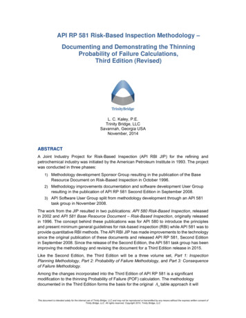
10 SCC Damage Factor – Alkaline Carbonate Stress Corrosion Cracking10.1 ScopeThe DF calculation for components subject to alkaline carbonate stress corrosion cracking (ACSCC)is covered in this section.10.2 Description of DamageACSCC is the common term applied to surface breaking cracks that occur at or near carbon and lowalloy steel welds under the combined action of tensile stress and in the presence of alkaline watercontaining moderate to high concentrations of carbonate ions (CO32-).On a macroscopic level, ACSCC typically propagates parallel to the weld in the adjacent basematerial, but can also occur in the weld deposit or heat-affected zones.At times surface inspection results of ACSCC may be mistaken for SSC or SOHIC, but further reviewwill show that ACSCC is usually located further from the toe of the weld into the residual stress field ofthe base material and can contain multiple parallel cracks. When cracking is in the weld metal, thepattern of cracking observed on the steel surface is sometimes described as a “spider web” of smallcracks, which often initiate at or interconnect with weld-related flaws that serve as local stress risers.Finally, from the microscopic perspective the cracking is characterized by predominantly intergranular,oxide-filled cracks similar in appearance to ACSCC found in caustic and amine services.Historically, ACSCC has been most prevalent in fluid catalytic cracking unit main (FCCU) fractionatoroverhead condensing and reflux systems, the downstream wet gas compression system, and the sourwater systems emanating from these areas. Based upon recent survey results, sour water stripperswith side-pump around designs, CO2 removal facilities for hydrogen manufacturing units and delayedcoker light ends units have been added to the list of affected units. There have also been cases ofACSCC in non-refining industries. In all instances, both piping and vessels are affected.Assuming the presence of an alkaline water phase containing H2S, three key parameters are used toassess the susceptibility of steel fabrications to ACSCC; pH of the water, carbonate ion concentrationof the water, and the residual stress level of the exposed carbon or low alloy steel.a) pH – Typically pHs are greater than 7.5 and process streams that are lower in H2S or higher in NH3causing higher pHs will be more susceptible to this form of ACSCC. Although H2S is often present, nothreshold level has been established; no evidence exists to indicate cyanides or polysulfides have animpact.b) Carbonates – Plants that generate more carbonate ions in the water will be more susceptible toACSCC.c) Residual Stresses – ACSCC appears to be very susceptible to residual stress levels so that weldedstructures and cold worked structures will be susceptible.Studies have concluded that the electrochemical potential of the alkaline water can be used toassess the likelihood of ACSCC. However, accurate measurement in a field environment is difficult.Therefore, further discussion of the electrochemical potential is outside the scope of this document.With regard to mitigation techniques, the application of a post fabrication stress-relieving heattreatment (e.g., post weld heat treatmentPWHT) is the most commonly used method of preventingACSCC in carbon and low alloy steels. A heat treatment of about 649-663 C (1,200-1,225 F) inaccordance with WRC 452 or AWS D1010 is considered effective to minimize residual stresses. Theheat treatment requirements apply to all exposed welds as well as any external welds with heataffected zones (HAZ) in contact with the service environment. Other mitigation techniques include:process barriers (either organic or metallic), alloy upgrades (solid or clad 300 series, Alloy 400 orother corrosion resistant alloys), effective water washing and inhibitor injection.10.3 Screening CriteriaIf the component’s material of construction of the component is carbon or low alloy steel and theprocess environment contains water at pH 7.5 in any concentration, then the component should beconsidered for evaluation for susceptibility to ACSCC. Another trigger would be changes in FCCU
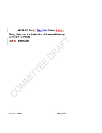
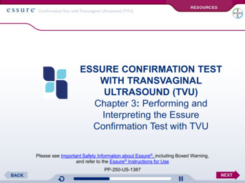
feed sulfur and nitrogen contents particularly when feed changes have reduced sulfur (low sulfurfeeds or hydroprocessed feeds) or increased nitrogen [7].10.4 Required DataThe basic component data required for analysis is given in Table 4.1 and the specific data required fordetermination of the ACSCC DF is provided in Table 10.1.10.5 Basic AssumptionsThe main assumption in determining the DF for ACSCC is that the damage can be characterized by asusceptibility parameter that is designated as high, medium, or low based on process environment,material of construction, and component fabrication variables (i.e. cold work, welding and heattreatment). A severity index is assigned based on the susceptibility parameter.If cracks are detected in the component during an inspection, the susceptibility is designated as High,and this will result in the maximum value for the Severity Index. Cracks that are found during aninspection should be evaluated using Fitness-For-Service methods in API 579-1/ASME FFS-1 [120].10.6 Determination of the Damage Factor10.6.1 OverviewA flow chart of the steps required to determine the DF for ACSCC is shown in Figure 10.1. Thefollowing sections provide additional information and the calculation procedure.10.6.2 Inspection EffectivenessInspections are ranked according to their expected effectiveness at detecting for ACSCC. Examplesof inspection activities that are both intrusive (requires entry into the equipment) and non-intrusive(can be performed externally), are provided in Annex 2.C, Table 2.C.9.4.If multiple inspections of a lower effectiveness have been conducted during the designated timeperiod, they can be equated to an equivalent higher effectiveness inspection in accordance withSection 3.4.3.10.6.3 Calculation of the Damage FactorThe following procedure may be used to determine the DF for ACSCC, see Figure 10.1a) STEP 1 – Determine the susceptibility for cracking using Figure 10.1 and Table 10.2 based on thepH of the water, CO32- concentration, and knowledge of whether the component has beenPWHT’dstress relieved. Note that a HIGH susceptibility should be used if cracking is confirmed to bepresent.b) STEP 2 – Based on the susceptibility in STEP 1, determine the severity index,SVI , from Table10.3.c) STEP 3 – Determine the time in-service, age , since the last Level A, B or C inspection wasperformed with no cracking detected or cracking was repaired. Cracking detected but not repairedshould be evaluated and future inspection recommendations based upon FFS evaluation.d) STEP 4 – Determine the number of inspections, and the corresponding inspection effectivenesscategory using Section 10.6.2 for past inspections performed during the in-service time. Combine theinspections to the highest effectiveness performed using Section 3.4.3.e) STEP 5 – Determine the base DF for ACSCC,D fBACSCC , using Table 6.3 based on the number of,and the highest inspection effectiveness determined in STEP 4, and the severity index,SVI , fromSTEP 2.f) STEP 6 – Calculate the escalation in the DF based on the time in-service since the last inspectionusing the age from STEP 3 and Equation (2.29). In this equation, it is assumed that the probability
for cracking will increase with time since the last inspection as a result of increased exposure to upsetconditions and other non-normal conditions.(2.29)10.7 NomenclatureageDACSCCfis the component in-service time since the last cracking inspection or service start dateis the DF for ACSCCD fBACSCCis the base value of the DF for ACSCCSVIis the severity index10.8 References1. R. D. Merrick, “Refinery Experiences with Cracking in Wet H2S Environments,” MaterialsPerformance 27, 1 (1988), pp. 30–36.2. J. H. Kmetz and D. J. Truax, “Carbonate Stress Corrosion Cracking of Carbon Steel in RefineryFCC Main Fractionator Overhead Systems,” NACE Paper #206, CORROSION/90.3. H. U. Schutt, “Intergranular Wet Hydrogen Sulfide Cracking,” NACE Paper #454, Corrosion/92 (seealso “Stress Corrosion Cracking of Carbon Steel in Amine Systems,” NACE paper #187,Corrosion/87) (see also Materials Performance 32, 11 (1993), pp. 55-60).4. E. Mirabel et al, “Carbonate-type Cracking in a FCC Wet Gas Compressor Station”, MaterialsPerformance, July, 1991, pp.41-45.5. NACE Publication 34108, “Review and Survey of Alkaline Carbonate Stress Corrosion Cracking inRefinery Sour Water”, NACE International, Houston, TX, 2008.6. M. Rivera et al, “Carbonate Cracking Risk Assessment for an FCCU Gas Plant”, Paper #04639,NACE International, Houston, TX, 2004.7. D. Milton et al, “FCCU Light Ends Plant Carbonate Cracking Experience”, Paper #07564, NACEInternational, Houston, TX 2007.8. WRC Bulletin 452, “Recommended Practices for Local Heating of Welds in Pressure Vessels”,Welding Research Council (WRC), Shaker Heights, OH.9. NACE International Publication 8X194, “Materials and Fabrication Practices for New PressureVessels Used in Wet H2S Refinery Service”, December 2006.10. NACE International Publication 34108, “Review and Survey of Alkaline Carbonate StressCorrosion Cracking in Refinery Sour Waters”, Appendix D, June 2013.11. API RP 571, Damage Mechanisms Affecting Fixed Equipment in the Refining Industry, AmericanPetroleum Institute, 2nd Edition, April 2011.12. API 579-1/ASME FFS-1 Fitness-For-Service, American Petroleum Institute, Washington, D.C.,20005, 2016.10.9 TablesTable 10.1 – Data Required for Determination of the Damage Factor – ACSCCRequired DataSusceptibilityCommentsThe susceptibility is determined by expert advice or using
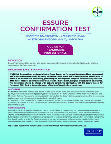
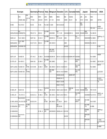
(Low, Medium, High)Presence of Water(Yes or No)pH of WaterCO32 Concentration in waterAge(years)Inspection EffectivenessCategoryNumber of inspectionsthe procedures in this section. This type of cracking maybe sporadic and may grow rapidly depending on subtlechanges in the process conditions. Periodic monitoring ofprocess pH and CO32 in FCC alkaline waters should bedone to determine cracking susceptibility.Determine whether free water is present in the component.Consider not only normal operating conditions, but alsostartup, shutdown, process upsets, etc.Determine the pH of the water phase. If analytical resultsare not readily available, it should be estimated by aknowledgeable process engineer.Determine the carbonate ion concentration of the waterphase present in this component. If analytical results arenot readily available, it should be estimated by aknowledgeable process engineer.Use inspection history to determine the time since the lastSCC inspection.The effectiveness category that has been performed on thecomponent.The number of inspections in each effectiveness categorythat have been performed.Table 10.2 – Susceptibility to Cracking – ACSCC[2]Susceptibility to Cracking as a Function of Residual Stress andCO32 pHEffective PWHTCO32 7pH 9.59.0 pH 9.58.5 pH 9.0 7.5 to 8.0 pH 8.5 7.5 pH 8.0 to 9.0 9.0pH 7.5 Concentration in the Water(1)Unknown or Ineffective PWHT and/or Possible Cold WorkingCO3 10 CO3 100 2 2 CO310,000 ppm(2) 10 ppmNoneCO32 CO32 CO31,000 ppm100 ppm1,000 HighNoneNoneNoneLowLowNoneNoneNoneNoneNoneNote 1: Traditional alkalinity titration methods (P,M alkalinity) are not effective for measurement of CO3in sour water.Note 2: In refinery processes, the concentration ofis typically less than 10,000 ppm
Table 10.3 – Determination of Severity Index – ACSCCSusceptibilityHighMediumLowNoneSeverity Index –SVI1,0001001002-
AMERICAN PETROLEUM INSTITUTEAPI RP 581 – RISK BASED INSPECTION METHODOLOGYBALLOT COVER PAGEDeveloped from the following chart:Document Rev 1 –07/26/2016Page 8 of 8
Title: MODIFICATION OF API 581 CARBONATE CRACKING – Confirmation Ballot Purpose: Modification of the damage factor to include susceptibility chart Impact: Changes in the damage factor criteria Rationale: To update Part 10 based on the modified susceptibility range. This was derived from NACE chart for pH versus Carbonate ion. Technical Reference(s): Primary Sponsor: Name: Huang Lin
![API Ballot: [Ballot ID] – API 510 & API 570, Deferrals, Rev05](/img/5/api510andapi570deferralsrev5.jpg)