Transcription
EE321 Electrical Machines 1Notes for Chapter 1CHAPTER 1 – Introduction to Machinery PrinciplesSummary:1. Basic concept of electrical machines fundamentals:o Rotational component measurements Angular Velocity, Acceleration Torque, Work, Power Newton’s Law of Rotationo Magnetic Field study Production of a Magnetic Field Magnetic Circuits2. Magnetic Behaviour of Ferromagnetic Materials3. How magnetic field can affect its surroundings: Faraday’s Law – Induced Voltage from a Time-Changing MagneticField. Production of Induced Force on a Wire. Induced Voltage on a Conductor moving in a Magnetic Field4. Linear DC Machines1
EE321 Electrical Machines 1Notes for Chapter 1Introduction1.Electric Machines mechanical energy to electric energy or vice versaMechanical energy Electric energy : GENERATORElectric energy mechanical energy : MOTOR2.Almost all practical motors and generators convert energy from one form to another through theaction of a magnetic field.3.Only machines using magnetic fields to perform such conversions will be considered in this course.4.When we talk about machines, another related device is the transformer. A transformer is a devicethat converts ac electric energy at one voltage level to ac electric energy at another voltage level.5.Transformers are usually studied together with generators and motors because they operate on thesame principle, the difference is just in the action of a magnetic field to accomplish the change involtage level.6.Why are electric motors and generators so common?- electric power is a clean and efficient energy source that is very easy to transmit overlong distances and easy to control.- Does not require constant ventilation and fuel (compare to internal-combustion engine),free from pollutant associated with combustion1. Basic concept of electrical machines fundamentals1.1 Rotational Motion, Newton’s Law and Power RelationshipAlmost all electric machines rotate about an axis, called the shaft of the machines. It is important tohave a basic understanding of rotational motion.Angular position, - is the angle at which it is oriented, measured from some arbitrary reference point.Its measurement units are in radians (rad) or in degrees. It is similar to the linear concept of distancealong a line.Conventional notation: ve value for anticlockwise rotation-ve value for clockwise rotationAngular Velocity, - Defined as the velocity at which the measured point is moving. Similar to theconcept of standard velocity where:v drdtwhere:r – distance traverse by the bodyt – time taken to travel the distance rFor a rotating body, angular velocity is formulated as: d dt(rad/s)where: - Angular position/ angular distance traversed by the rotating bodyt – time taken for the rotating body to traverse the specified distance, .2
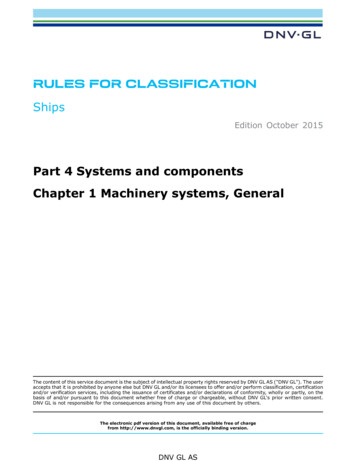
EE321 Electrical Machines 1Notes for Chapter 1Angular acceleration, - is defined as the rate of change in angular velocity with respect to time. Itsformulation is as shown: d (rad/s2)dtTorque, 1.In linear motion, a force applied to an object causes its velocity to change. In the absence of anet force on the object, its velocity is constant. The greater the force applied to the object, themore rapidly its velocity changes.2.Similarly in the concept of rotation, when an object is rotating, its angular velocity is constantunless a torque is present on it. Greater the torque, more rapid the angular velocity changes.3.Torque is known as a rotational force applied to a rotating body giving angular acceleration,a.k.a. ‘twisting force’.4.Definition of Torque: (Nm)‘Product of force applied to the object and the smallest distance between the line of action of theforce and the object’s axis of rotation’ Force perpendicular distance F r sin Directionof rotationrsin rsin FWork, W – is defined as the application of Force through a distance. Therefore, work may be defined as:W FdrAssuming that the direction of F is collinear (in the same direction) with the direction of motion andconstant in magnitude, hence,W FrApplying the same concept for rotating bodies,Assuming that is constant,W d W (Joules)3
EE321 Electrical Machines 1Notes for Chapter 1Power, P – is defined as rate of doing work. Hence,P dWdt(watts)Applying this for rotating bodies,d dtd dt P This equation can describe the mechanical power on the shaft of a motor or generator.Newton’s Law of RotationNewton’s law for objects moving in a straight line gives a relationship between the force applied to theobject and the acceleration experience by the object as the result of force applied to it. In general,F mawhere:F – Force appliedm – mass of objecta – resultant acceleration of objectApplying these concept for rotating bodies, J (Nm)where: - TorqueJ – moment of inertia - angular acceleration1.2 The Magnetic FieldMagnetic fields are the fundamental mechanism by which energy is converted from one form toanother in motors, generators and transformers.First, we are going to look at the basic principle – A current-carrying wire produces a magnetic fieldin the area around it.Production of a Magnetic Field1.Ampere’s Law – the basic law governing the production of a magnetic field by a current: H dl Inetwhere H is the magnetic field intensity produced by the current Inet and dl is a differential element oflength along the path of integration. H is measured in Ampere-turns per meter.4
EE321 Electrical Machines 1Notes for Chapter 12.Consider a current currying conductor is wrapped around a ferromagnetic core; ICSAN turnsmean path length, lc3.Applying Ampere’s law, the total amount of magnetic field induced will be proportional to theamount of current flowing through the conductor wound with N turns around the ferromagneticmaterial as shown. Since the core is made of ferromagnetic material, it is assume that a majorityof the magnetic field will be confined to the core.4.The path of integration in Ampere’s law is the mean path length of the core, l c. The currentpassing within the path of integration Inet is then Ni, since the coil of wires cuts the path ofintegration N times while carrying the current i. Hence Ampere’s Law becomes,Hlc Ni H 5.NilcIn this sense, H (Ampere turns per metre) is known as the effort required to induce a magneticfield. The strength of the magnetic field flux produced in the core also depends on the material ofthe core. Thus,B HB magnetic flux density (webers per square meter, Tesla (T))µ magnetic permeability of material (Henrys per meter)H magnetic field intensity (ampere-turns per meter)6.The constant may be further expanded to include relative permeability which can be defined asbelow: r owhere: o – permeability of free space (a.k.a. air)7.Hence the permeability value is a combination of the relative permeability and the permeability offree space. The value of relative permeability is dependent upon the type of material used. Thehigher the amount permeability, the higher the amount of flux induced in the core. Relativepermeability is a convenient way to compare the magnetizability of materials.8.Also, because the permeability of iron is so much higher than that of air, the majority of the fluxin an iron core remains inside the core instead of travelling through the surrounding air, which haslower permeability. The small leakage flux that does leave the iron core is important indetermining the flux linkages between coils and the self-inductances of coils in transformers andmotors.5
EE321 Electrical Machines 1Notes for Chapter 19.In a core such as in the figure,B H NilcNow, to measure the total flux flowing in the ferromagnetic core, consideration has to be made interms of its cross sectional area (CSA). Therefore, BdAAWhere: A – cross sectional area throughout the coreAssuming that the flux density in the ferromagnetic core is constant throughout hence constantA, the equation simplifies to be: BATaking into account past derivation of B, NiAlc2. Magnetics CircuitsThe flow of magnetic flux induced in the ferromagnetic core can be made analogous to an electricalcircuit hence the name magnetic circuit.The analogy is as follows: A V-RF Ni(mmf)Electric Circuit Analogy1.-Reluctance, RMagnetic Circuit AnalogyReferring to the magnetic circuit analogy, F is denoted as magnetomotive force (mmf) which issimilar to Electromotive force in an electrical circuit (emf). Therefore, we can safely say that F isthe prime mover or force which pushes magnetic flux around a ferromagnetic core at a value of Ni(refer to ampere’s law). Hence F is measured in ampere turns. Hence the magnetic circuitequivalent equation is as shown:F R2. (similar to V IR)The polarity of the mmf will determine the direction of flux. To easily determine the direction offlux, the ‘right hand curl’ rule is utilised:a) The direction of the curled fingers determines the current flow.b) The resulting thumb direction will show the magnetic flux flow.6
EE321 Electrical Machines 1Notes for Chapter 13.The element of R in the magnetic circuit analogy is similar in concept to the electrical resistance.It is basically the measure of material resistance to the flow of magnetic flux. Reluctance in thisanalogy obeys the rule of electrical resistance (Series and Parallel Rules). Reluctance is measuredin Ampere-turns per weber.Series Reluctance,Req R1 R2 R3 .Parallel Reluctance,1111 .Req R1 R2 R34.The inverse of electrical resistance is conductance which is a measure of conductivity of amaterial. Hence the inverse of reluctance is known as permeance, P where it represents thedegree at which the material permits the flow of magnetic flux.1RF since R FPP Also, NiAlc Ni F P 5. Alc Alc Alc,R lc ABy using the magnetic circuit approach, it simplifies calculations related to the magnetic field in aferromagnetic material, however, this approach has inaccuracy embedded into it due toassumptions made in creating this approach (within 5% of the real answer). Possible reason ofinaccuracy is due to:a) The magnetic circuit assumes that all flux are confined within the core, but in reality a smallfraction of the flux escapes from the core into the surrounding low-permeability air, and this fluxis called leakage flux.b) The reluctance calculation assumes a certain mean path length and cross sectional area (csa) ofthe core. This is alright if the core is just one block of ferromagnetic material with no corners, forpractical ferromagnetic cores which have corners due to its design, this assumption is notaccurate.7
EE321 Electrical Machines 1Notes for Chapter 1c) In ferromagnetic materials, the permeability varies with the amount of flux already in thematerial. The material permeability is not constant hence there is an existence of non-linearityof permeability.d) For ferromagnetic core which has air gaps, there are fringing effects that should be taken intoaccount as shown:NSExample 1.1A ferromagnetic core is shown. Three sides of this core are of uniform width, while the fourth side issomewhat thinner. The depth of the core (into the page) is 10cm, and the other dimensions are shown inthe figure. There is a 200 turn coil wrapped around the left side of the core. Assuming relativepermeability µr of 2500, how much flux will be produced by a 1A input current?Solution:3 sides of the core have the same csa, while the 4th side has a different area. Thus the core can be dividedinto 2 regions:(1) the single thinner side(2) the other 3 sides taken togetherThe magnetic circuit corresponding to this core:8
EE321 Electrical Machines 1Notes for Chapter 1Example 1.2Figure shows a ferromagnetic core whose mean path length is 40cm. There is a small gap of 0.05cm inthe structure of the otherwise whole core. The csa of the core is 12cm2, the relative permeability of thecore is 4000, and the coil of wire on the core has 400 turns. Assume that fringing in the air gap increasesthe effective csa of the gap by 5%. Given this information, find(a) the total reluctance of the flux path (iron plus air gap)(b) the current required to produce a flux density of 0.5T in the air gap.Solution:The magnetic circuit corresponding to this core is shown below:9
EE321 Electrical Machines 1Notes for Chapter 1Example 1.3Figure shows a simplified rotor and stator for a dc motor. The mean path length of the stator is 50cm,and its csa is 12cm2. The mean path length of the rotor is 5 cm, and its csa also may be assumed to be12cm2. Each air gap between the rotor and the stator is 0.05cm wide, and the csa of each air gap(including fringing) is 14cm2. The iron of the core has a relative permeability of 2000, and there are 200turns of wire on the core. If the current in the wire is adjusted to be 1A, what will the resulting fluxdensity in the air gaps be?Solution:To determine the flux density in the air gap, it is necessary to first calculate the mmf applied to the coreand the total reluctance of the flux path. With this information, the total flux in the core can be found.Finally, knowing the csa of the air gaps enables the flux density to be calculated.The magnetic cct corresponding to this machine is shown below.10
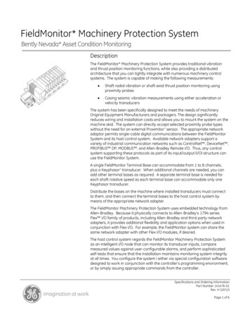
EE321 Electrical Machines 1Notes for Chapter 1Magnetic Behaviour of Ferromagnetic Materials1.Materials which are classified as non-magnetic all show a linear relationship between the fluxdensity B and coil current I. In other words, they have constant permeability. Thus, for example,in free space, the permeability is constant. But in iron and other ferromagnetic materials it is notconstant.2.For magnetic materials, a much larger value of B is produced in these materials than in free space.Therefore, the permeability of magnetic materials is much higher than µo. However, thepermeability is not linear anymore but does depend on the current over a wide range.3.Thus, the permeability is the property of a medium that determines its magneticcharacteristics. In other words, the concept of magnetic permeability corresponds to the ability ofthe material to permit the flow of magnetic flux through it.4.In electrical machines and electromechanical devices a somewhat linear relationship between Band I is desired, which is normally approached by limiting the current.5.Look at the magnetization curve and B-H curve. Note: The curve corresponds to an increase of DCcurrent flow through a coil wrapped around the ferromagnetic core (ref: Electrical MachineryFundamentals 4th Ed. – Stephen J Chapman).6.When the flux produced in the core is plotted versus the mmf producing it, the resulting plot lookslike this (a). This plot is called a saturation curve or a magnetization curve. A small increase inthe mmf produces a huge increase in the resulting flux. After a certain point, further increases inthe mmf produce relatively smaller increases in the flux. Finally, there will be no change at all asyou increase mmf further. The region in which the curve flattens out is called saturation region,and the core is said to be saturated. The region where the flux changes rapidly is called theunsaturated region. The transition region is called the ‘knee’ of the curve.7.From equation H Ni/lc F/lc and BA, it can be seen that magnetizing intensity is directlyproportional to mmf and magnetic flux density is directly proportional to flux for any given core.B µH slope of curve is the permeability of the core at that magnetizing intensity. The curve (b)shows that the permeability is large and relatively constant in the unsaturated region and thengradually drops to a low value as the core become heavily saturated.8.Advantage of using a ferromagnetic material for cores in electric machines and transformers is thatone gets more flux for a given mmf than with air (free space). 11
EE321 Electrical Machines 1Notes for Chapter 19.If the resulting flux has to be proportional to the mmf, then the core must be operated in theunsaturated region.10.Generators and motors depend on magnetic flux to produce voltage and torque, so they need asmuch flux as possible. So, they operate near the knee of the magnetization curve (flux not linearlyrelated to the mmf). This non-linearity as a result gives peculiar behaviours to machines.11.As magnetizing intensity H increased, the relative permeability first increases and then starts todrop off.Example 1.5A square magnetic core has a mean path length of 55cm and a csa of 150cm2. A 200 turn coil of wire iswrapped around one leg of the core. The core is made of a material having the magnetization curveshown below. Find:a) How much current is required to produce 0.012 Wb of flux in the core?b) What is the core’s relative permeability at that current level?c) What is its reluctance?12
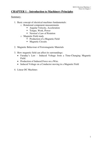
EE321 Electrical Machines 1Notes for Chapter 1Energy Losses in a Ferromagnetic CoreI. Hysteresis Loss1.Discussions made before concentrates on the application of a DC current through the coil. Nowlet’s move the discussion into the application of AC current source at the coil. Using ourunderstanding previously, we can predict that the curve would be as shown, 1st PositiveCycle2nd NegativeCycleFTheoretical ac magnetic behaviour for flux in a ferromagnetic core.2.Unfortunately, the above assumption is only correct provided that the core is ‘perfect’ i.e. there areno residual flux present during the negative cycle of the ac current flow. A typical flux behaviour(or known as hysteresis loop) in a ferromagnetic core is as shown in the next page.13
EE321 Electrical Machines 1Notes for Chapter 1Typical Hysterisis loop when ac current is applied.3.Explanation of Hysteresis Loop Apply AC current. Assume flux in the core is initially zero.As current increases, the flux traces the path ab. (saturation curve)When the current decreases, the flux traces out a different path from the one when the currentincreases.When current decreases, the flux traces out path bcd.When the current increases again, it traces out path deb.NOTE: the amount of flux present in the core depends not only on the amount of currentapplied to the windings of the core, but also on the previous history of the flux in the core.HYSTERESIS is the dependence on the preceding flux history and the resulting failure toretrace flux paths.When a large mmf is first applied to the core and then removed, the flux path in the core willbe abc.When mmf is removed, the flux does not go to zero – residual flux. This is how permanentmagnets are produced.To force the flux to zero, an amount of mmf known as coercive mmf must be applied in theopposite direction.14
EE321 Electrical Machines 1Notes for Chapter 14.Why does hysteresis occur? To understand hysteresis in a ferromagnetic core, we have to look into the behaviour of itsatomic structure before, during and after the presence of a magnetic field. The atoms of iron and similar metals (cobalt, nickel, and some of their alloys) tend to havetheir magnetic fields closely aligned with each other. Within the metal, there is an existenceof small regions known as domains where in each domain there is a presence of a smallmagnetic field which randomly aligned through the metal structure.This as shown below:An example of a magnetic domain orientation in a metal structure beforethe presence of a magnetic field. Magnetic field direction in each domain is random as such that the net magnetic field is zero. When mmf is applied to the core, each magnetic field will align with respect to the direction ofthe magnetic field. That explains the exponential increase of magnetic flux during the early stageof magnetisation. As more and more domain are aligned to the magnetic field, the total magneticflux will maintain at a constant level hence as shown in the magnetisation curve (saturation). When mmf is removed, the magnetic field in each domain will try to revert to its random state. However, not all magnetic field domain’s would revert to its random state hence it remained inits previous magnetic field position. This is due to the lack of energy required to disturb themagnetic field alignment. Hence the material will retain some of its magnetic properties (permanent magnet) up until anexternal energy is applied to the material. Examples of external energy may be in the form ofheat or large mechanical shock. That is why a permanent magnet can lose its magnetism if it isdropped, hit with a hammer or heated. Therefore, in an ac current situation, to realign the magnetic field in each domain during theopposite cycle would require extra mmf (also known as coercive mmf). This extra energy requirement is known as hysteresis loss. The larger the material, the more energy is required hence the higher the hysteresis loss. Area enclosed in the hysteresis loop formed by applying an ac current to the core is directlyproportional to the energy lost in a given ac cycle.15
EE321 Electrical Machines 1Notes for Chapter 1II. Eddy Current Loss1.2.3.4.5.A time-changing flux induces voltage within a ferromagnetic core.These voltages cause swirls of current to flow within the core – eddy currents.Energy is dissipated (in the form of heat) because these eddy currents are flowing in a resistivematerial (iron)The amount of energy lost to eddy currents is proportional to the size of the paths they followwithin the core.To reduce energy loss, ferromagnetic core should be broken up into small strips, or laminations,and build the core up out of these strips. An insulating oxide or resin is used between the strips, sothat the current paths for eddy currents are limited to small areas.Conclusion:Core loss is extremely important in practice, since it greatly affects operating temperatures, efficiencies,and ratings of magnetic devices.3. How Magnetic Field can affect its surroundings3.1 FARADAY’S LAW – Induced Voltage from a Time-Changing Magnetic FieldBefore, we looked at the production of a magnetic field and on its properties. Now, we will look at thevarious ways in which an existing magnetic field can affect its surroundings.1.Faraday’s Law:‘If a flux passes through a turn of a coil of wire, voltage will be induced in the turn of the wire that isdirectly proportional to the rate of change in the flux with respect of time’eind d dtIf there is N number of turns in the coil with the same amount of flux flowing through it, hence:eind Nd dtwhere: N – number of turns of wire in coil.Note the negative sign at the equation above which is in accordance to Lenz’ Law which states:‘The direction of the build-up voltage in the coil is as such that if the coils were short circuited, it wouldproduce current that would cause a flux opposing the original flux change.’16
EE321 Electrical Machines 1Notes for Chapter 1Examine the figure below: If the flux shown is increasing in strength, then the voltage built up in the coil will tend toestablish a flux that will oppose the increase.A current flowing as shown in the figure would produce a flux opposing the increase.So, the voltage on the coil must be built up with the polarity required to drive the current throughthe external circuit. So, -eindNOTE: In Chapman, the minus sign is often left out because the polarity of the resulting voltagecan be determined from physical considerations.2.Equation eind -d /dt assumes that exactly the same flux is present in each turn of thecoil. This is not true, since there is leakage flux. This equation will give valid answer if thewindings are tightly coupled, so that the vast majority of the flux passing thru one turn of the coildoes indeed pass through all of them.3.Now consider the induced voltage in the ith turn of the coil,ei d idtSince there is N number of turns,eind N ei 1N i 1 id idtd N i dt i 1 The equation above may be rewritten into,eind where (flux linkage) is defined as:d dtN ii 1(weber-turns)17
EE321 Electrical Machines 1Notes for Chapter 14.Faraday’s law is the fundamental property of magnetic fields involved in transformer operation.5.Lenz’s Law in transformers is used to predict the polarity of the voltages induced in transformerwindings.3.2Production of Induced Force on a Wire.1.A current carrying conductor present in a uniform magnetic field of flux density B, would producea force to the conductor/wire. Dependent upon the direction of the surrounding magnetic field, theforce induced is given by:F i l B where:i – represents the current flow in the conductorl – length of wire, with direction of l defined to be in the direction of current flowB – magnetic field density2.The direction of the force is given by the right-hand rule. Direction of the force depends on thedirection of current flow and the direction of the surrounding magnetic field. A rule of thumb todetermine the direction can be found using the right-hand rule as shown below:Thumb(resultant force)Index Finger(current direction)MiddleFinger(Magnetic Flux Direction)3.Right Hand ruleThe induced force formula shown earlier is true if the current carrying conductor is perpendicularto the direction of the magnetic field. If the current carrying conductor is position at an angle to themagnetic field, the formula is modified to be as follows:F ilB sin Where: - angle between the conductor and the direction of the magnetic field.4.In summary, this phenomenon is the basis of an electric motor where torque or rotational force ofthe motor is the effect of the stator field current and the magnetic field of the rotor.Example 1.7The figure shows a wire carrying a current in the presence of amagnetic field. The magnetic flux density is 0.25T, directed into thepage. If the wire is 1m long and carries 0.5A of current in thedirection from the top of the page to the bottom, what are themagnitude and direction of the force induced on the wire?18
EE321 Electrical Machines 1Notes for Chapter 13.3Induced Voltage on a Conductor Moving in a Magnetic Field1.If a conductor moves or ‘cuts’ through a magnetic field, voltage will be induced between theterminals of the conductor at which the magnitude of the induced voltage is dependent upon thevelocity of the wire assuming that the magnetic field is constant. This can be summarised in termsof formulation as shown:eind (v x B) lwhere:v – velocity of the wireB – magnetic field densityl – length of the wire in the magnetic field2.Note: The value of l (length) is dependent upon the angle at which the wire cuts through themagnetic field. Hence a more complete formula will be as follows:eind (v x B)l cosθwhere: - angle between the conductor and the direction of (v x B)3.The induction of voltages in a wire moving in a magnetic field is fundamental to the operation of alltypes of generators.Example 1.8The figure shows a conductor moving with a velocity of5m/s to the right in the presence of a magnetic field. Theflux density is 0.5T into the page, and the wire is 1m length,oriented as shown. What are the magnitude and polarity ofthe resulting induced voltage?Example 1.9Figure shows a conductor moving with a velocity of 10m/sto the right in a magnetic field. The flux density is 0.5T, outof the page, and the wire is 1m in length. What are themagnitude and polarity of the resulting induced voltage?19
EE321 Electrical Machines 1Notes for Chapter 14.The Linear DC MachineLinear DC machine is the simplest form of DC machine which is easy to understand and it operatesaccording to the same principles and exhibits the same behaviour as motors and generators. Consider thefollowing:SwitchBReindVB -Equations needed to understand linear DC machines are as follows:Production of Force on a current carrying conductorF i l B Voltage induced on a current carrying conductor moving in a magnetic fieldeind (v x B) lKirchoff’s voltage lawVB iR eind 0 VB eind iR 0Newton’s Law for motionFnet ma20
EE321 Electrical Machines 1Notes for Chapter 1Starting the Linear DC Machine1.To start the machine, the switch is closed.2.Current will flow in the circuit and the equation can be derived from Kirchoff’s law:Since, VB iR eind i VB eindRAt this moment, the induced voltage is 0 due to no movement of the wire (the bar is at rest).3.As the current flows down through the bar, a force will be induced on the bar. (Section 1.6 a currentflowing through a wire in the presence of a magnetic field induces a force in the wire).F i (l B ) ilB sin 90 ilBDirection of movement: Right4.When the bar starts to move, its velocity will increase, and a voltage appears across the bar.eind (v B)l vBl sin 90 ilBDirection of induced potential: positive upwards5.Due to the presence of motion and induced potential (eind), the current flowing in the bar will reduce(according to Kirchhoff’s voltage law). The result of this action is that eventually the bar will reacha constant steady-state speed where the net force on the bar is zero. This occurs when eind has risenall the way up to equal VB. This is given by:VB eind vsteady state Bl vsteady state VBBl21
EE321 Electrical Machines 1Notes for Chapter 16.The above equation is true assuming that R is very small. The bar will continue to move along atthis no-load speed forever unless some external force disturbs it. Summarization of the starting oflinear DC machine is sketched in the figure below:22
EE321 Electrical Machines 1Notes for Chapter 1The Linear DC Machine as a Motor1.Assume the linear machine is initially running at the no-load steady state condition (as before).2.What happen when an external load is applied? See figure below:3.A force Fload is applied to the bar opposing the direction of motion. Since the bar was initially atsteady state, application of the force Fload will result in a net force on the bar in the directionopposite the direction of motion.Fnet Fload Find4.Thus, the bar will slow down (the resulting acceleration a Fnet/m is negative). As soon as thathappen, the induced voltage on the bar dr
1. Electric Machines mechanical energy to electric energy or vice versa Mechanical energy Electric energy : GENERATOR Electric energy mechanical energy : MOTOR 2. Almost all practical motors and generators convert energy from one form to another through the action of a magnetic field. 3.