Transcription
DIGITAL MULTIMETERUSER’S Manual
DIGITAL MULTIMETERCONTENTS1.General instructions.11.1 Precautions safety measures .11.1.1 Preliminary .11.1.2 During use .21.1.3 Symbols .41.1.4 Instructions .51.2 Protec tion mechanisms. .62. Description.72.1 Instrument Fa miliarization. 72.2 LCD display . 82.3 Keypad . 102.4 Rotary switch . 112.5 Terminals . 133. Function description.143.1 General function .143.1.1 Data hold mode .143.1.2 Manual ranging and auto range mode .143.1.3 Battery saver.153.1.4 Relative measurement mode .153.2 Measurement functions .163.2.1 AC and DC Voltage measurement .163.2.2 Resistance measurement .19DIGITAL MULTIMETERCONTENTS3.2.3 Diode test.213.2.4 Continuity check .233.2.5 Capacitance measurement .253.2.6 Frequency and duty cyclemeasurement .273.2.7 Temperature measurement .273.2.8 Current measurement .284. Specifications . 314.1 General specifications . 314.2 Measurement Specifications .324.2.1 DC Voltage . 324.2.2 AC Voltage . 324.2.3 Frequency .334.2.4 Resistance .334.2.5 Diode Test . 334.2.6 Continuity . 344.2.7 Capac itance. 344.2.8 Temperature . 344.2.9 DC Current . 354.2.10 AC Current . 355. Maintenance . 365.1 Replacing the Batteries . 365.2 Replacing the Test Lead(or alligator clip) . 366. Accessories . 36
DIGITAL MULTIMETER1.General InstructionsThis instrument complies with IEC 1010-1 (61010 - 1@IEC: 2001), CAT II 1000V and CAT III 600V overvoltagestandards. See Specifications.To get the best service from this instrument, readcarefully this user's manual and respect the detailedsafety precautions.International symbols used on the Meter and in thismanual are explained in chapter 1.1.31.1P recautions safety measures1.1.1 Preliminary MEASUREMENT CATEGORY III is applicable to testand measuring circuits connected to the distributionpart of the building's low-voltage MAINS installation.NOTE: Examples are measurements on distributionboards, circuit-breakers, wiring, including cables,bus-bars, junction boxes, switches, socket-outlets inthe fixed installation, and equipment for industrial useand some other equipment, for example, stationarymotors with permanent connection to the fixedinstallation. MEASUREMENT CATEGORY II is applicable to testand measuring circuits connected directly to utilizationpoints (socket outlets and similar points) of the lowvoltage MAINS installation.NOTE: Examples are measurements on householdappliances, portable tools and similar equipment. Measurement category I is for measurementsperformed on circuits not directly connected to MAINS.NOTE: Examples are measurements on circuits notderived from MAINS, and specially protected (internal)MAINS derived circuits. In the latter case, transient01DIGITAL MULTIMETERstresses are variable; for that reason, requires that thetransient withstand capability of the equipment is madeknown to the user. When using this Multimeter, the user must observe allnormal safety rules concerning:- protection against the dangers of electric current.- protection of the Multimeter against misuse. For your own safety, only use the test probes suppliedwith the instrument. Before use, check that they are ingood condition.1.1.2 During use If the meter is used near noise generating equipment,be aware that display may become unstable or indicatelarge errors. Do not use the meter or test leads if they look damaged. Use the meter only as specified in this manual;otherwise, the protection provided by the meter may beimpaired. Use extreme caution when working around bareconductors or bus bars. Do not operate the meter around explosive gas, vapor,or dust. Verify a Meter's operation by measuring a knownvoltage. Do not use the Meter if it operates abnormally.Protection may be impaired. When in doubt, have theMeter serviced. Uses the proper terminals, function, and range for yourmeasurements. When the range of the value to be measured is unknown,check that the range initially set on the multimeter is thehighest possible or, wherever possible, choose theautoranging mode. To avoid damages to the instrument, do not exceed the02
DIGITAL MULTIMETERmaximum limits of the input values shown in thetechnical specification tables. When the multimeter is linked to measurement circuits,do not touch unused terminals. Caution when working with voltages above 60Vdc or30Vac rms. Such voltages pose a shock hazard. When using the probes, keep your fingers behind thefinger guards. When making connections, connect the common testlead before connecting the live test lead; whendisconnecting, disconnect the live test lead beforedisconnecting the common test lead. Before changing functions, disconnect the test leadsfrom the circuit under test. For all dc functions, including manual or auto-ranging,to avoid the risk of shock due to possible improperreading, verify the presence of any ac voltages by firstusing the ac function. Then select a dc voltage rangeequal to or greater than the ac range. Disconnect circuits power and discharge allhigh-voltage capacitors before testing resistance,continuity, diodes, or capacitance. Never perform resistance or continuity measurementson live circuits. Before measuring current, check the meter's fuse andturn off power to the circuit before connecting the meterto the circuit. In TV repair work, or when carrying out measurementson power switching circuits, remember that highamplitude voltage pulses at the test points can damagethe multimeter. Use of a TV filter will attenuate anysuch pulses. Use only three AAA batteries, properly installed in theMeter's battery case, to power the Meter.03DIGITAL MULTIMETER Replace the battery as soon as the battery indicatorappears. With a low battery, the Meter might producefalse readings that can lead to electric shock andpersonal injury. Do not measure voltages above 600V in CAT III,or 1000V in CAT II installations. When in REL mode the REL symbol is displayed.Caution must be used because hazardous voltage maybe present. Do not operate the Meter with the case (or part of thecase) removed.1.1.3 Symbols:Symbols used in this manual and on the instrument:Caution: refer to the instruction manual.Incorrect use may result in damage to thedevice or its components.AC (Alternating Current)DC (Direct Current)AC or DCEarth groundDouble insulatedFuse04
DIGITAL MULTIMETER1.1.4 Instructions Remove test leads from the Meter before opening theMeter case or battery cover. When servicing the Meter, use only specifiedreplacement parts. Before opening up the instrument, always disconnectfrom all sources of electric current and make sure youare not charged with static electricity, which maydestroy internal components. Any adjustment, maintenance or repair work carriedout on the meter while it is live should be carried outonly by appropriately qualified personnel, after havingtaken into account the instructions in this presentmanual. A "qualified person" is someone who is familiar with theinstallation, construction and operation of theequipment and the hazards involved. He is trained andauthorized to energize and de-energize circuits andequipment in accordance with established practices. When the instrument is opened up, remember thatsome internal capacitors can retain a dangerouspotential even after the instrument is switched off. If any faults or abnormalities are observed, take theinstrument out of service and ensure that it cannot beused until it has been checked out. If the meter is not going to be used for a long time, takeout the battery and do not store the meter in hightemperature or high humidity environment.05DIGITAL MULTIMETER1.2 Protection mechanismsThis instrument is fitted with various protectionmechanisms: Varistor protection for limiting transients of over 1000Vat the VΩ terminal. A PTC (positive temperature coefficient) resistorprotects against permanent overvoltages of up to 1000Vduring resistance, capacitance, temperature, continuityand diode test measurements. Selected function or range isn't suitable for the insertedred test lead terminal. Pull out the red test lead and thenselect the function or range06
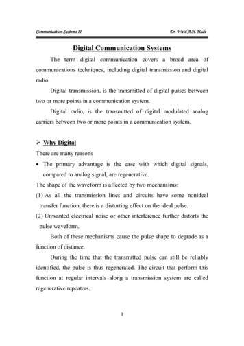
DIGITAL MULTIMETERDIGITAL MULTIMETER2.2 LCD Display2. DESCRIPTION2.1 Instrument FamiliarizationSee Table 1 indicated for information about the LCDdisplay.Table 1. Display SymbolsNumber Symbol1.LCD display2.Keypad3.Rotary switch4.Terminals5.Battery cover1207MeaningThe battery is low.Warning: To avoid false readings,which could lead to possible electricshock or personal injury, replace thebattery as soon as the batteryindicator appears.Indicates negative readings.08
DIGITAL MULTIMETER3ACIndicator for ac voltage or current.AC voltage and current are displayedas the average of the absolute valueof the input, calibrated to indicate theequivalent rms value of a sine wave.4DCIndicator for dc voltage or current.589REL CV, mVThe Meter is in the Relativemeasurement mode C:Celsius scale. The unit oftemperature.Volts. The unit of voltage.V:-3mV: Millivolt. 1x10 or 0.001 volts.Amperes (amps). The unit ofcurrent.A, mA, mA: Milliamp. 1x10 - 3 or 0.001µAamperes.-6µA: Microamp. 1x10 or 0.000001amperesA:11Ω,kΩ,MΩOhm. The unit of resistance.Ω:3kΩ: Kilohm. 1x10 or 1000 ohms.6MΩ: Megohm. 1x10 or 1,000,000ohms.09%Percent. The unit of Duty cycle.Hertz. The unit of frequency incycles/second.Hz, kHz, Khz: Kilohertz. 1x10 3 or 1000 hertz.6MHzMHZ: Meghertz. 1x10 or 1,000,000hertz.Hz:11µF, nFF:µF:nF:The Meter is in the Diode Test modeThe Meter is in the Continuity Checkmode.DATA-H The Meter is in the Data Hold mode10%The Meter is in the Autorange modein which the meter automaticallyAUTO selects the range with the bestresolution.67DIGITAL MULTIMETERFarad. The unit of capacitance.Microfarad.1x10 - 6 or 0.000001farads.Nanofarad. 1x10 - 9 or0.000000001 farads.The input is too large for the selectedrange.122.3 KeypadSee Table 2 indicated for information about the keypadoperations.KeyOperation performedFunctionSwitches between Resistancemeasurement, Diode Test andOΩ(YELLOW) A mA µA Continuity check.Switches between dc and acPower-upcurrent.OptionDisables automatic power-offfeature.HOLDAny switch Press HOLD to enter and exitthe Data Hold modeposition10
DIGITAL MULTIMETERRANGERELHz %1.Press RANGE to enter themanual ranging mode.2.Press RANGE to stepV V Ωthrough the ranges availableA, mA andfor the selected function.µA3.Press and hold RANGE for2 seconds to return toautoranging.Any switch Press REL to enter and exitthe Relative measurementpositionmode.1 Press to start the frequencycounter.V , A, mA 2 Press again to enter dutycycle (duty factor) mode.and µA3 Press again to exit thefrequency counter mode.DIGITAL MULTIMETERV AC Voltage measurementVDC Voltage measurementmVDC milliVolt measurementResistance measurement / DiodeTest / Continuity CheckΩCapacitance measurementAmAµATempDC or AC Current measurementfrom 0.01A to 10.00A.DC or AC current measurementsfrom 0.01mA to 400mA.DC or AC current measurementsfrom 0.1µA to 4000µA.Temperature measurement2.4 Rotary switchSee Table 3 indicated for information about the rotaryswitch positions.Table 3. Rotary Switch Positions1112
DIGITAL MULTIMETER2.5 TerminalsSee Table 4 indicated for information about the terminals.DIGITAL MULTIMETER3. FUNCTION DESCRIPTION3.1 General Functions3.1.1 DATA HOLD modeData Hold mode makes the meter stop updating thedisplay. Enabling Data Hold function in autorange modemakes the meter switch to Manual ranging mode, but thefull-scale range remains the same. Data Hold functioncan be cancelled by changing the measurement mode,pressing RANGE key, or push HOLD key again.To enter and exit the Data Hold mode:1. Press HOLD key (short press). Fixes the display onthe current value, DATA-H is displayed.2. A second short press returns the meter to normal mode.TerminalCOMTempVΩµA/mAADescriptionTerminal receiving the black test lead as acommon reference.Terminal receiving the red test lead forvoltage, resistance, capacitance,frequency, Temperature, diode andcontinuity measurements.Terminal receiving the red test lead for ,µmA and frequency measurements.Terminal receiving the red test lead for 4A,10A and frequency measurements.133.1.2 Manual ranging and Autorange modeThe Meter has both manual ranging and autorangeoptions. In the autorange mode, the Meter selects the bestrange for the input detected. This allows you to switchtest points without having to reset the range. In the manual ranging mode, you select the range. Thisallows you to override autorange and lock the meter ina specific range. The Meter defaults to the autorange mode inmeasurement functions that have more than one range.When the Meter is in the autorange mode, AUTO isdisplayed.To enter and exit the manual range mode:1. Press RANGE key. The Meter enters the manualranging mode. AUTO turns off. Each presses ofRANGE key increments the range. When the highestrange is reached, the Meter wraps to the lowest range.14
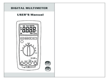
DIGITAL MULTIMETERNOTE:If you manually change the measurement range afterentering the Data Hold modes, the Meter exits this mode.2. To exit the manual ranging mode, press and hold downRANGE key for two seconds. The Meter returns to theautorange mode and AUTO is displayed.3.1.3 Battery Saver The Meter enters the "sleep mode" and blanks thedisplay if the Meter is on but not used for 30 minutes. Press the HOLD key or rotate the rotary switch to wakethe meter up. To disable the Sleep mode, hold down the yellow keywhile turning the meter on.3.1.4 Relative measurement modeThe Meter will display relative measurement in allfunctions except frequency.To enter and exit the relative measurement mode:1. With the Meter in the desired function, touch the testleads to the circuit on which you want futuremeasurement to be based.2. Press REL key to store the measured value andactivate the relative measurement mode. Thedifference between the reference value andsubsequent reading is displayed.3. Press REL key for more than 2 seconds to return theMeter to normal operation.15DIGITAL MULTIMETER3.2 Measurement Functions3.2.1 AC and DC Voltage measurementWarningTo avoid electrical shock and/or damage to theinstrument, do not attempt to take any voltagemeasurement that might exceeds 1000Vdc or1000Vac rms.To avoid electrical shock and/or damage to theinstrument, do not apply more than 1000Vdc or1000Vac rms between the common terminal andthe earth ground.Voltage is the difference in electrical potential betweentwo points. The polarity of ac (alternating current) voltagevaries over time; the polarity of dc (direct current) voltageis constant.The Meter's voltage ranges are 400.0mV, 4.000V, 40.00V,400.0V and 1000V. (AC 400.0mV range only exists inmanual ranging mode).To measure ac or dc voltage (set up and connect theMeter as shown in Figure 2):1. Set rotary switch to the DCV, ACV or DCmV range.2. Connect the black and red test leads to the COM andV terminals respectively.3. Connect the test leads to the circuit being measured4. Read the displayed value. The polarity of red test leadconnection will be indicated when making a DCVmeasurement.16
DIGITAL MULTIMETERDIGITAL MULTIMETERNOTE: Unstable display may occur especially at 400mV range,even though you do not put test leads into inputterminals, in this case, if an erroneous reading issuspected, short the V terminal and the COM terminal,and make sure the zero display. For better accuracy when measuring the dc offset of anac voltage, measure the ac voltage first. Note the acvoltage range, then manually select a dc voltage rangeequal to or higher than the ac range. This improves theaccuracy of the dc measurement by ensuring that theinput protection circuits are not activated.DC VoltageAC Voltage1718
DIGITAL MULTIMETER3.2.2 Resistance measurementWarningTo avoid electrical shock and/or damage to theinstrument, disconnect circuit power anddischarge all high-voltage capacitors beforemeasuring resistance.Resistance is an opposition to current flow.The unit of resistance is the ohm (Ω). The Metermeasures resistance by sending a small current throughthe circuit. Because this current flows through allpossible paths between the probes, an in-circuitresistance reading represents the total resistance of allpaths between the probes.The Meter's resistance ranges are 400.0Ω, 4.000kΩ,40.00kΩ, 400.0kΩ, 4.000MΩ and 40.00MΩ.To measure resistance (set up the Meter as shown infigure 3):1. Set the rotary switch to Ωrange.2. Connect the black and red test leads to the COM andVΩ terminals respectively.3. Connect the test leads to the circuit being measuredand read the displayed value.Some tips for measuring resistance: The measured value of a resistor in a circuit is oftendifferent from the resistor's rated value. This is becausethe Meter's test current flows through all possible pathsbetween the probe tips. In order to ensure the best accuracy in measurementof low resistance, short the test leads beforemeasurement and memory the test probe resistance inmind. This necessary to subtract for the resistance ofthe test leads.19DIGITAL MULTIMETER The resistance function can produce enough voltageto forward-bias silicon diode or transistor junctions,causing them to conduct. To avoid this, do not use the40MΩ range for in-circuit resistance measurements. On 40MΩ range, the meter may take a few seconds tostabilize reading. This is normal for high resistancemeasuring. When the input is not connected, i.e. at open circuit,the figure "OL" will be displayed for the overrangecondition.20
DIGITAL MULTIMETERDIGITAL MULTIMETER3.2.3 Diode TestWarningTo avoid electrical shock and/or damage to theinstrument, disconnect circuit power anddischarge all high-voltage capacitors beforetesting diodes.Use the diode test to check diodes, transistors, and othersemiconductor devices. The diode test sends a currentthrough the semiconductor junction, then measures thevoltage drop across the junction, A good silicon junctiondrops between 0.5V and 0.8V.The Meter's resistance ranges are 400.0Ω, 4.000kΩ,40.00kΩ, 400.0kΩ, 4.000MΩ and 40.00MΩ.To test a diode out of a circuit (set up the Meter as shownin Figure 4):1. Set the rotary switch to Ωrange.2. Press the yellow key once to activate Diode Test.3. Connect the black and red test leads to the COM andVΩ terminals respectively.4. For forward-bias readings on any semiconductorcomponent, place the red test lead on the component'sanode and place the black test lead on the component'scathode.5. The meter will show the approx. forward voltage of thediode.In a circuit, a good diode should still produce a forwardbias reading of 0.5V to 0.8V; however, the reverse-biasreading can vary depending on the resistance of otherpathways between the probe tips.2122
DIGITAL MULTIMETERDIGITAL MULTIMETER3.2.4 Continuity CheckWarningTo avoid electrical shock and/or damage to theinstrument, disconnect circuit power anddischarge all high-voltage capacitors beforetesting for Continuity.Continuity is a complete path for current flow.The beeper sounds if a circuit is complete. These briefcontacts cause the Meter to emit a short beep.To test for continuity (set up the Meter as shown inFigure 5):1. Set the rotary switch to Ωrange.2. Press the yellow key twice to activate Continuity Check.3. Connect the black and red test leads to the COM andterminals respectively.4. Connect the test leads to the resistance in the circuitbeing measured.5. When the test lead to the circuit is below 75Ω, acontinuous beeping will indicate it.Note:Continuity test is available to check open/short of thecircuit.2324
DIGITAL MULTIMETERDIGITAL MULTIMETER3.2.5 Capacitance measurementWarningTo avoid electrical shock and/or damage to theinstrument, disconnect circuit power anddischarge all high-voltage capacitors beforemeasuring capacitance. Use the dc voltagefunction to confirm that the capacitor isdischarged.Capacitance is the ability of a component to store anelectrical charge.The unit of capacitance is the farad(F). Most capacitors are in the nanofarad to microfaradrange. The Meter measures capacitance by chargingthe capacitor with a known current for a known period oftime, measuring the resulting voltage, then calculatingthe capacitance. The measurement takes about 1second per range.The Meter's capacitance ranges are 50.00nF, 500.0nF,5.000µF, 50.00µF and 100.0µF.To measure capacitance (set up the Meter as shown inFigure 6):1. Set the rotary switch to range.2. Connect the black and red test leads to the COM andterminals respectively (or you can measure thecapacitance by using Multi Function Socket).3. Connect the test leads to the capacitor being measuredand read the displayed value.Note: The meter may take a few seconds to stabilize reading.This is normal for high capacitance measuring. To improve the accuracy of measurements less than50nF, subtract the residual capacitance of the Meterand leads. Below 500pF, the accuracy of measurements isunspecified.2526
DIGITAL MULTIMETER3.2.6 Frequency and Duty Cycle measurementWarningDo not measure Frequency on high voltage( 1000V) to avoid electrical shock hazard and/ordamage to the instrument.Frequency is the number of cycles a voltage or currentsignal completes each second.The Meter can measure Frequency or Duty Cycle whilemaking either an AC Voltage or AC Current measurement.To measure frequency or Duty Cycle:1. With the meter in the desired function (AC Voltage orAC Current), press the Hz % key.2. Read the frequency of the AC signal on the display.3.To make a duty cycle measurement, press the Hz %key again.4. Read the percent of duty cycle on the display.Note:In noisy environment, it is preferable to use shield cablefor measuring small signal.3.2.7 Temperature measurementWarningTo avoid electrical shock and/or damage to theinstrument, do not apply more than 1000V DC or1000V AC rms between the Temp terminal and theCOM terminal.To avoid electrical shock, do not use thisinstrument when voltages at the measurementsurface exceed 60V dc or 24V rms. AC.To avoid damage or burns. Do not maketemperature measurements in microwave ovens.27DIGITAL MULTIMETERTo measure temperature:1. Set the rotary switch to Temp range and the LCD willshow the current environment temperature.2. Insert “K” type thermocouples into the COM terminaland Temp terminal (or you can insert it by using MultiFunction Socket),Takings care to observe thecorrect polarity.3. Touch the object with the thermocouple probe formeasurement.4. Read the stable reading from LCD.3.2.8 Current measurementWarningTo avoid damage to the Meter or injury if the fuseblows, never attempt an in-circuit currentmeasurement where the open-circuit potential toearth is greater than 250V.To avoid damage to the meter, check the meter'sfuse before proceeding. Use the proper terminals,function, and range for your measurement. Neverplace the probes in parallel with a circuit orcomponent when the leads are plugged into thecurrent terminals.Current is the flow of electrons through a conductor.The Meter's current ranges are 400.0µA, 4000µA,40.00mA, 400.0mA, 4.000A and 10.00A.28
DIGITAL MULTIMETERDIGITAL MULTIMETERTo measure current (set up the Meter as shown inFigure 7):1. Turn off power to the circuit. Discharge all high voltagecapacitors.2. Set the rotary switch to the µA, mA or A range.3. Press the yellow key to select DCA or ACA measuringmode.4. Connect the black test lead to the COM terminal andthe red test leads to the mA terminal for a maximum of400mA. For a maximum of 10A, move the red test leadto the A terminal.5. Break the circuit path to be tested.Touch the blackprobe to the more negative side of the break; touch thered probe to the more positive side of the break.(Reversing the leads will give a negative reading, butwill not damage the Meter.)6. Turn on power to the circuit; then read the display. Besure to note the measurement units at the right side ofthe display (µA, mA or A). When only the figure "OL"displayed, it indicates overrange situation and thehigher range has to be selected.7. Turn off power to the circuit and discharge all highvoltage capacitors. Remove the Meter and restore thecircuit to normal operation.2930
DIGITAL MULTIMETER4 TECHNICAL SPECIFICATIONS4.1 General specifications Environment conditions:1000V CAT II and 600V CAT IIIPollution degree: 2Altitude 2000mOperating temperature: 0 40 C, 32 F 122 F( 80% RH, 10 C non-condensing)Storage temperature: -10 60 C, 14 F 140 F( 70% RH,battery removed) Temperature Coefficient: 0.1(specified accuracy) / C ( 18 C or 28 C) MAX. Voltage between terminals and earthground: 1000V AC rms or 1000V DC. Fuse Protection: µA and mA: F 500mA/250V Ø5x20;A: F 10A/250V Ø6.3x32. Sample Rate: 3 times/sec for digital data. Display: 3 3/4 digits LCD display. Automatic indicationof functions and symbols. Range selection: automatic and manual. Over Range indication: LCD will display "OL". Low Battery Indication:Theis displayed when thebattery is under the proper operation range. Polarity indication: "-" displayed automatically. Power source: 4.5V Battery type: AAA 1.5V. Dimensions: 185(L)87(W)53(H) mm. Weight: 360g. Approx. (battery included).DIGITAL MULTIMETER4.2 Measurement specificationsAccuracy is specified for one year after calibration, atoperating temperatures of 18 C to 28 C, with relativehumidity at 0% to 75%.Accuracy specifications take the form of: (% ofReading Number of Least Significant Digits)4.2.1 DC VoltageMeasuring Range curacy (1.0% reading 10dgt) (0.5% reading 3dgt)- Overload protection: 1000V DC or AC rms- Frequency Range: 40Hz 500Hz- Manual Range only4.2.2 AC VoltageMeasuring Range curacy (3.0% reading 3dgt) (1.0% reading 3dgt)- Overload protection: 1000V DC or AC rms- Frequency Range: 40Hz 500Hz- Manual Range only3132
DIGITAL MULTIMETER4.2.3 FrequencyFunction50.00Hz4.2.6 0kHz0.001kHz50kHz0.01kHz100kHz0.1kHz (0.1% reading 3dgt)4.2.4 ResistanceMeasuring Range �100Ω4.000MΩ1kΩ10kΩDescriptionIf measured resistance is less than75Ω, buzzer will sound.- Overload protection: 1000V DC or AC rmsFunction4.2.7 CapacitanceFunctionResolution- Overload protection: 1000V DC or AC rms40.00MΩDIGITAL MULTIMETERAccuracy (0.5% reading 3dgt)50nF10pF500nF100pF5μF1nF50μF10nF100μF100nF (0.5% reading 2dgt) (1.5% reading 3dgt)4.2.8 TemperatureFunctionResolution-55 C 0 C1 C 400 C400 C 1000 C4.2.5 Diode testDescriptionDisplays approx. forward0.001Vbiased voltage- Overload protection: 1000V DC or AC rms33 (3.0% reading 5dgt)- Overload protection: 1000V DC or AC rms- Overload protection: 1000V DC or AC rmsFunction ResolutionAccuracy (3.0% reading 10dgt)0.1 C1 CAccuracy (9.0% of rdg 2 C) (2.0% of rdg 1 C) 2.0% of rdg- Overload protection: 1000V DC or AC rms- 1 Temperature specification do not includethermocouple errors.34
DIGITAL MULTIMETER4.2.9 DC CurrentMeasuring Range mA1μA0.1mA10mAAccuracy (1.5% reading 3dgt)DIGITAL MULTIMETERA and mA ranges, 10A dc or 10A ac rms for A ranges.For measurements 5A, 4 minutes maximum ON tomeasure 10 minutes OFF; Above 10A unspecified.-Frequency Range: 40Hz-200Hz-Response: Average, calibrated in rms of sine wave (1.5% reading 3dgt)5. Maintenance (1.5% reading 3dgt)WarningTo prevent electric shock and damage to the meteror personal injury, remove test lead beforeopening battery cover.-Overload protection: F 10A H 250 V fuse for A range.F 500mA H 250 V fuse for A and mA ranges.-Maximum input current: 400mA dc or 400mA ac rms forA and mA ranges, 10A dc or 10A ac rms for A ranges.For measurements 5A, 4 minutes maximum ON tomeasure 10 minutes OFF; Above 10A unspecified.-Frequency Range: 40Hz-200Hz-Response: Average, calibrated in rms of sine wave5.1 Replacing the Batteries5.1.1 When the“”ymbol appears, it indicates thebatteries need to be replaced.5.1.2 Unscrew the battery cover and remove it from themeter.5.1.3 Replace the used batteries with new AAA batteries.5.1.4 Replace the battery cover and secure it to the meter.4.2.10 AC CurrentMeasuring Range Resolution5.2 Replacing the Test Lead (or alligator clip)If insulation on leads is damaged, replace A1mA10mAAccuracy (1.5% reading 3dgt) (1.5% reading 3dgt) (1.5% reading 3dgt)-Overload protection: F 10A H 250 V fuse for A range.F 500mA H 250 V fuse for A and mA ranges.-Maximum input current: 400
Symbols used in this manual and on the instrument: C atio n: r efr to the isrc n m l. In co et u se m ay r ult in dmge to the d evice or i ts c omp n . AC (Alternating Current) DC (Direct Current) AC or DC Earth ground Double insulated Fuse DIGITAL MULTIMETER DIGITAL MULTIMETER