Transcription
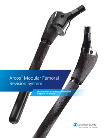
Arcos Modular FemoralRevision SystemBroach and Calcar Proximal BodiesSurgical Technique
Table of ContentsPre-operative Planning.2Patient Positioning and Surgical Approach.2Removal of a Cemented Component.3Removal of a Cementless Stem.3Calcar/Broach Proximal Bodies & PPS Distal Stems Sterile Field Technique.4Preparation of the Diaphysis. 4Preparation of the Metaphysis. 4Broaching the Metaphysis. 5Calcar Resection. 6Trial Reduction. 7Implant Assembly. 8Implant Insertion. 8Inserting the Locking Screw. 9Final Reduction. 9Calcar/Broach Proximal Bodies & STS Distal Stems Sterile Field Techinque. 10Preparation of the Diaphysis. 10Trialing the Distal Stem. 10Preparation of the Metaphysis. 11Broaching the Metaphysis. 12Calcar Resection. 13Trial Reduction. 14Implant Assembly. 15Implant Insertion. 16Inserting the Locking Screw. 16Final Reduction. 17Trochanteric Reattachment Technique. 18Attaching the Trochanteric Bolt Guide. 18Preparing For Auxiliary Implant Attachment. 19Final Attachment of the Auxiliary Implant. 21In-Femur Assembly.22Implant Assembly. 22Inserter Disassembly. 25Inserting the Locking Screw. 26Final Reduction. 27Taper Compression Assembly.28Proximal Body Insertion. 28Inserter Disassembly. 30Inserting the Locking Screw. 31Disengaging the Taper Junction.32Disengaging the Proximal Body from the Distal Stem Implant. 32
2 Arcos Broach/Calcar Proximal Body Surgical TechniqueFigure 1Figure 2Pre-operative PlanningPatient Positioningand Surgical ApproachWhen planning a hip revision utilizing the ArcosModular Femoral Revision System, carefully reviewthe indications and contraindications for usereferenced within the package insert.Patient position should be determined by thesurgeon’s preferred approach. The goal of the surgicalapproach is to establish adequate visualization of theanatomy (Figure 2).The Arcos Modular Femoral Revision System is notdesigned for use in a fully unsupported proximalfemur. Bone stock of adequate quality must bepresent and appraised at the time of surgery. Theuse of medial and/or lateral strut grafts may benecessary to support the taper junction in cases ofsevere proximal deficiency.Utilizing A/P and M/L X-rays and implant templateswill assist in determining the correct implant size,offset and position for a stable reconstruction(Figure 1). Final determination frequently cannot bemade until the actual time of surgery. However, withappropriate planning, a consistent operative planwith alternatives can be formulated.
3 Arcos Broach/Calcar Proximal Body Surgical TechniqueFigure 3Figure 4Figure 5Removal of a Cemented ComponentRemoval of a Cementless StemOnce the stem has been removed from the cementmantle by utilizing universal extraction instruments ormanufacturer specific instruments, ensure all cement isremoved prior to preparation of the femur for the Arcosfemoral components (Figure 3). This can be achievedusing the Ultra-Drive cement removal system orcement removal tools. An osteotomy of the femur maybe necessary to facilitate removal of the cement.Removal of a cementless stem may be difficult due tothe biologic fixation that may exist between the implantand bone. When removing a proximally porous coatedstem, it may be necessary to perform an osteotomyof the femur just below the level of the porous coatingto assist in stem removal (Figure 4).Note: An extended trochanteric osteotomy may benecessary if removing an extensively coated stem.Sectioning the stem and utilizing trephine reamerscan assist in the removal of the porous coated distalsegment of a cementless stem (Figure 5).
4 Arcos Broach/Calcar Proximal Body Surgical TechniqueCalcar/Broach Proximal Bodies & PPS Distal StemsSterile Field TechniqueProximal ReamerTransition ReamerFigure 6Figure 7Figure 8Preparation of the DiaphysisPreparation of the MetaphysisTo prepare the femur for a PPS coated distal stem,select flexible or thin shaft reamers and sequentiallyream the femur two cortical diameters or 2–3 cmbelow the distal defect, increasing size until cortical“chatter” is achieved (Figure 6).To prepare the proximal femur for the tapered regionof the PPS distal stem and proximal body, assemblethe transition reamer that is the same size as thedesired distal stem into the proximal reamer and pressdown on the collar at the top of the proximal reamer tosecurely lock the two instruments together (Figure 7).Ream the proximal femur with the modular (transition/proximal) reamer, sequentially increasing the size of theproximal reamer, until the desired size (A–F) and the60 mm proximal body height is achieved. The 60 mmetch mark of the proximal reamer should align with thetip of the greater trochanter (Figure 8).Note: When utilizing flexible reamers, ream thecanal in 0.5 mm increments until cortical “chatter”is achieved. The final reamer diameter should beline-to-line or 0.5 mm larger than the diameter ofthe desired implant, depending on bone quality.Note: Reaming over a guide is recommended.The Arcos distal reamers are designed to preparethe femur for a bowed distal stem and arecannulated to accommodate a guide wire.
5 Arcos Broach/Calcar Proximal Body Surgical TechniqueFigure 9Figure 10Figure 11Broaching the MetaphysisOnce the desired size and 60 mm proximal bodyheight has been achieved utilizing the modularreamer, loosely assemble the proximal broach and thedistal stem trial together using the 3.5 mm hex driver(Figure 9).Note: Assemble the proximal broach and distalstem trial loose to allow the distal stem to find theappropriate position in the femur.Broach the proximal femur sequentially, until the finalbroach size matches the last proximal reamer used(Figure 10). Verify that the broach is advanced into thefemur, oriented to the desired anteversion, and the60 mm etch mark on the broach handle is aligned withthe tip of the greater trochanter.Once the desired broach size is obtained, removethe broach handle and tighten the broach’s capturedscrew with the 3.5 mm hex driver to lock the broachinto place (Figure 11).Note: Locking the broach and stem trial togetherwill aid in matching the orientation of the trial to thefinal implant.
6 Arcos Broach/Calcar Proximal Body Surgical TechniqueCalcar/Broach Proximal Bodies & PPS Distal StemsSterile Field Technique 0 10 20Figure 12Figure 13Calcar ResectionIf utilizing the calcar proximal body implant, determinethe level of deficiency in the proximal femur, align theresection guide to the broach and mark the desiredresection with a saw (Figure 12). Remove the broachand stem trial with the broach handle and completethe calcar resection.Insert either the large or small platform trial into theslot corresponding with the calcar resection level(Figure 13).Note: The large platform should be utilized for a 0 resection level and the small platform should beutilized for the 10 or 20 resection levels.Reattach the broach handle to the assembled trial andinsert the trial into the femur to verify it seats to thedesired level.
7 Arcos Broach/Calcar Proximal Body Surgical TechniqueStandard OffsetHigh OffsetFigure 14Figure 15Utilizing the modular neck and head trials, perform atrial reduction of the hip and determine if the selectedoffset, leg length and joint stability are appropriate(Figures 14 and 15). When performing the trial rangeof motion, ensure the absence of impingement ofthe neck on the rim of the acetabular component oracetabular liner.Once the desired offset, leg length and joint stabilityhave been achieved, remove the modular neckand head trials. Reattach the broach handle to theassembled trial and remove the trial from the femur.Detach the broach handle from the assembled trial.Trial ReductionNote: The gold modular trials indicate standardoffset and the black trials indicate high offset.
8 Arcos Broach/Calcar Proximal Body Surgical TechniqueCalcar/Broach Proximal Bodies & PPS Distal StemsSterile Field TechniqueFigure 16Figure 17Figure 18Implant AssemblyImplant InsertionWith the trial still assembled in the sterile field,assemble the distal stem and proximal body implantsto match the orientation of the assembled trial(Figure 16).With the proximal inserter still assembled to theimplant, ensure the anti-rotation tabs are properlylocked and insert the implant into the femur until thedesired depth is achieved (Figure 18).Note: If utilizing a slotted stem, a straightosteotome can be used in the slot of the trial andimplant to properly orient the distal stem in relationto the proximal body.When the desired orientation of the implants hasbeen achieved, thread the green proximal bodyinserter to the assembled implant and impact thetaper junction with at least three blows of the malleton the back table (Figure 17).
9 Arcos Broach/Calcar Proximal Body Surgical TechniqueTorque Limiting PositionFigure 19Figure 20Inserting the Locking ScrewFinal ReductionTo lock the distal and proximal body implants, threadthe locking screw into the top of the proximal bodyusing the 3.5 mm hex driver and the T-handle intorque limiting position until a “click” is felt and heard(Figure 19).If desired, another trial reduction can be accomplishedprior to selecting final head size and impacting themodular head onto the stem (Figure 20). Provisionalheads in seven neck lengths allow an additional trialreduction using the actual implant to ensure properleg length and stability. After fully seating the femoralcomponent, impact the appropriate modular headonto the clean, dry taper.Note: The screw can be used to lock the proximalbody and distal stem together before the implantsare inserted into the femur. If this is done, checkthe security of the screw once the implant has beenfully seated.
10 Arcos Broach/Calcar Proximal Body Surgical TechniqueCalcar/Broach Proximal Bodies & STS Distal StemsSterile Field TechniqueLocked PositionFigure 21Figure 22Preparation of the DiaphysisTrialing the Distal StemTo prepare the femur for an STS distal stem, selectthe STS reamers (silver reamers for 150 mm stemlength and gold reamers for a 190 mm stem length).Assemble the STS reamer to the T-handle and turn thehandle from torque limiting to the locked position.When distal femoral reaming is complete, select thestem trial that is the same diameter as the final reamerand the necessary length for stem stability. Thread theblack distal trial inserter into the stem trial and insertthe stem trial into the femur, matching the etcheddepth mark on the inserter to the depth achieved fromthe last STS reamer used (Figure 22).Ream the femur in 1 mm increments by hand until thereamer advances to the 60 mm mark, referencing thetip of the greater trochanter (Figure 21).Note: The final depth of the implant may vary fromthe depth of the reamer. How aggressively thefemur is prepared and the quality of the bonemay impact the depth that the final implant willseat. If the final implant sits proud of the desiredream depth, note the difference between these andutilize the last reamer used to ream deeper into thefemur. Reaming the femur by hand may help avoidany discrepancy between the reamed depth andthe final depth of the implant.Note: The stem trial and reamer are the same size.Both are 1 mm smaller than the femoral implant.
11 Arcos Broach/Calcar Proximal Body Surgical TechniqueProximal ReamerSTS ReamerFigure 23Preparation of the MetaphysisTo prepare the proximal femur, assemble the finalSTS reamer into the proximal reamer and pressdown on the collar at the top of the proximal reamerto securely lock the two instruments together(Figure 23). Ream the proximal femur, sequentiallyincreasing the size of the proximal reamer, untilthe desired size (A–F) and the 60 mm proximal bodyheight is achieved (Figure 24).Figure 24
12 Arcos Broach/Calcar Proximal Body Surgical TechniqueCalcar/Broach Proximal Bodies & STS Distal StemsSterile Field TechniqueFigure 25Figure 26Broaching the MetaphysisOnce the desired size and 60 mm proximal bodyheight has been achieved utilizing the STS/proximalreamers, assemble the proximal broach body and thedistal stem trial together using the 3.5 mm hex driver(Figure 25).Note: To keep the broach aligned with the femur,utilize the distal stem trial previously used.Broach the proximal femur sequentially, until thefinal broach size matches the last proximal reamerused (Figure 26). Verify that the broach body isadvanced into the femur, oriented to the desiredanteversion and the 60 mm etch mark on thebroach handle is aligned with the tip of the greatertrochanter. Once the broach has been seated to thedesired level, remove the broach handle from theassembled trial.
13 Arcos Broach/Calcar Proximal Body Surgical Technique 0 10 20Figure 27Figure 28Calcar ResectionIf utilizing the calcar proximal body implant, determinethe level of deficiency in the proximal femur, align theresection guide to the broach and mark the desiredresection with a saw (Figure 27). Remove the broachand stem trial with the broach handle and completethe calcar resection.Insert either the large or small platform trial into theslot corresponding with the calcar resection level(Figure 28).Note: The large platform should be utilized for a 0 resection level and the small platform should beutilized for the 10 or 20 resection levels.Reattach the broach handle to the assembled trial andinsert the trial into the femur to verify that it seats tothe desired level.
14 Arcos Broach/Calcar Proximal Body Surgical TechniqueCalcar/Broach Proximal Bodies & STS Distal StemsSterile Field TechniqueStandard OffsetHigh OffsetFigure 29Figure 30Utilizing the modular neck and head trials, perform atrial reduction of the hip and determine if the selectedoffset, leg length and joint stability are appropriate(Figures 29 and 30). When performing the trial rangeof motion, ensure the absence of impingement ofthe neck on the rim of the acetabular component oracetabular liner.Once the desired offset, leg length and joint stabilityhave been achieved, remove the modular neckand head trials. Reattach the broach handle to theassembled trial and remove the trial from the femur.Detach the broach handle from the assembled trial.Trial ReductionNote: The gold modular trials indicate standardoffset and the black trials indicate high offset.
15 Arcos Broach/Calcar Proximal Body Surgical TechniqueFigure 31Figure 32Implant AssemblyWith the trial still assembled in the sterile field,assemble the distal stem and proximal body implantsto match the orientation of the assembled trial(Figure 31).Note: If utilizing the 190 mm stem, ensure the bevelat the distal tip of the stem is oriented anteriorly.When the desired orientation of the implants has beenachieved, thread the green proximal body inserter tothe assembled implant and impact the taper junctionwith at least three blows of the mallet on the back table(Figure 32).
16 Arcos Broach/Calcar Proximal Body Surgical TechniqueCalcar/Broach Proximal Bodies & STS Distal StemsSterile Field TechniqueTorque Limiting PositionFigure 33Figure 34Implant InsertionInserting the Locking ScrewWith the proximal inserter still assembled to theimplant, ensure the anti-rotation tabs are properlylocked and insert the final implant into the femur untilthe desired depth is achieved (Figure 33).To lock the distal and proximal body implants, threadthe locking screw into the top of the proximal bodyusing the 3.5 mm hex driver and the T-handle intorque limiting position until a “click” is felt and heard(Figure 34).Note: The final depth of the implant may varyfrom the depth of the reamer in this step. Howaggressively the femur is prepared and the qualityof the bone may impact the depth that the finalimplant will seat. If the final implant sits proudof the desired ream depth, note the differencebetween these and utilize the last reamer used toream deeper into the femur. Reaming the femur byhand may help avoid any discrepancy between thereamed depth and the final depth of the implant.Note: The screw can be used to lock the proximalbody and distal stem together before the implantsare inserted into the femur. If this is done, checkthe security of the screw once the implant has beenfully seated.
17 Arcos Broach/Calcar Proximal Body Surgical TechniqueFigure 35Final ReductionIf desired, another trial reduction can be accomplishedprior to selecting final head size and impacting themodular head onto the stem (Figure 35). Provisionalheads in seven neck lengths allow an additional trialreduction using the actual implant to ensure properleg length and stability. After fully seating the femoralcomponent, impact the appropriate modular headonto the clean, dry taper.
18 Arcos Broach/Calcar Proximal Body Surgical TechniqueTrochanteric Reattachment TechniqueFigure 36Figure 37Attaching the Trochanteric Bolt GuideAll proximal body designs accept a bolt and clawexcept the 50A Cone and 50A Calcar bodies.Once the final implant has been reduced, theosteotomy can be repaired and stabilized by choosingone of the auxiliary options available in the ArcosSystem and attaching it directly to the implant.Depending on the surgical approach and operativehip, select the appropriate trochanteric bolt guideinstrument (Figure 36).Use the 5.0 mm hex driver to thread the trochantericbolt guide into the insertion hole on the proximalbody, ensuring the anti-rotation tabs are locked tothe proximal body implant. Place the trochantericfragment between the implant and the trochantericbolt guide (Figure 37).If utilizing the trochanteric claw use the claw trials(large or small) to select the needed width.Note: Guide may be easier to attach before hip isreduced.
19 Arcos Broach/Calcar Proximal Body Surgical TechniqueEngraved Line25 mmBoth havegrooves toaccept cableattachments100 mmGuideHex DriverNarrowclaw option(16 mm)Wideclaw option(17.5 mm)Figure 38T-handleFigure 39Preparing for Auxiliary ImplantAttachmentNote: Both the large and small claw are 100 mmin length, measured from the top to bottom. Thebutton is 25 mm in diameter (Figure 38).Once the trochanteric fixation option has beendetermined, compress the auxiliary implant to thebone fragment by threading the plunger tightly againstthe auxiliary implant using the 5.0 mm hex driver andT-handle in the torque limiting position (Figure 39).Note: If utilizing the claw auxiliary option, ensurethat the head of the plunger is aligned with a holein the claw to ensure that the bolt will pass throughthe claw into the implant.Select the bolt length that corresponds with the depthmarks on the outside of the trochanteric bolt guide asmeasured according to the position of the engravedline on the plunger. Choose the trochanteric bolt drillbit that matches the size of the proximal body implant(Size A–G) regardless of height or body style.Example: If a size B Cone body is used, selectthe size B trochanteric bolt drill bit. Selecting thecorrect size will prevent the drill from contactingthe implant.Note: Bolts are available in 2 mm increments.
20 Arcos Broach/Calcar Proximal Body Surgical TechniqueTrochanteric Reattachment TechniqueFigure 40Figure 41Preparing for Auxiliary ImplantAttachment (cont.)Advance the appropriate size drill bit through theplunger until the built-in stop bottoms out on thecylindrical surface of the outrigger (Figure 40).Note: It is not possible to drill through the bolt holeon the claw trial, preparation must be performedwith the final implant in place.Compress the arms of the trochanteric bolt guidetightly to the auxiliary implant and remove themeasurement plunger with the 5.0 mm hex driver(Figure 41). Attach the 5.0 mm hex driver to theT-handle and set to torque limiting position.
21 Arcos Broach/Calcar Proximal Body Surgical TechniqueFigure 42Figure 43Figure 44Final Attachment of the AuxiliaryImplantThread the bolt through the trochanteric bolt guideand into the proximal body until a “click” is felt andheard (Figure 42).Once the bolt is secured to the implant, unthread thetrochanteric bolt guide from the proximal body usingthe 5.0 mm hex driver (Figure 43).Note: It may be necessary to give the T-handle afew small taps with the mallet to ensure the boltdrops into the hole in the proximal body.Note: If utilizing the claw auxiliary option, cablesmay be added in the grooves of the claw foradditional stability (Figure 44).Note: If the trochanteric bolt guide is difficult toremove, unthread the trochanteric bolt by 1 2 aturn, remove the guide and retighten the bolt withthe T-handle in torque limiting position.
22 Arcos Broach/Calcar Proximal Body Surgical TechniqueIn-Femur AssemblyProximal/Distal InserterDistal FastenerProximal FastenerFigure 45Figure 46Figure 47Implant AssemblyThe in-femur assembly tool can be utilized with anyproximal body and PPS coated distal stem constructand was designed to allow for a bowed distal stem toseat in the proper anatomic orientation, independentof the proximal body implant.Once the diaphysis and metaphysis has been preparedand trialed, the in-femur assembly tool can be utilizedfor the final insertion of the implant and to securelylock the taper junction.Thread the proximal fastener into the insertion holeon the proximal body implant (Figure 45). Slide thefastener into the gray proximal/distal inserter, pullingback on the inserter collar and locking the fastenerinto the inserter (Figure 46). Ensure that the antirotation tabs are locked to the implant.Place the distal fastener that matches the selectedproximal body height into the proximal/distal inserterhandle. Depress the button at the top of the proximal/distal inserter handle and insert the assembly rod intothe inserter (Figure 47).
23 Arcos Broach/Calcar Proximal Body Surgical Technique2–3 cmFigure 48Figure 49Insert the 5.0 mm hex driver to the top of the proximal/distal inserter handle, hold the taper junction apartand thread the distal fastener into the distal stem(Figure 48).Attach the proximal/distal inserter handle strike plate,tightening until a “click” is felt and heard. Impact theproximal body until it is 2–3 cm proud of the desireddepth (Figure 49).Note: Do not engage the taper junction whenthreading the distal fastener rod into the distalstem.Note: When a “click” is heard, while tightening thestrike plate, the proximal body and distal stem areseparated and cannot be locked during insertioninto the femur.
24 Arcos Broach/Calcar Proximal Body Surgical TechniqueIn-Femur AssemblyTorque WrenchProximal/DistalInserter HandleAnti-rotationHandleFigure 50Figure 51Implant Assembly (cont.)To fully engage the taper junction, attach the torquewrench to the end of the proximal/distal inserterhandle strike plate, place the anti-rotation handleover the implant neck and tighten until 300 in-lbs isindicated on the torque wrench shaft (Figure 50).Disassemble the torque wrench and anti-rotationhandle. Impact the stem to the desired depth(Figure 51).
25 Arcos Broach/Calcar Proximal Body Surgical TechniqueTorque WrenchProximal/DistalInserter HandleAnti-rotation HandleFigure 52Figure 53Figure 54Inserter DisassemblyTo loosen the strike plate, use the anti-rotation handleto hold the neck of the implant. Turn the torquewrench counter-clockwise and depress the buttonat the top of the proximal/distal inserter handle andunthread the strike plate (Figure 52).Unthread the distal fastener from the distal stemimplant using the 5.0 mm hex. Disengage theproximal/distal inserter by pulling back on the insertercollar (Figures 53 and 54).
26 Arcos Broach/Calcar Proximal Body Surgical TechniqueIn-Femur AssemblyTorque Limiting PositionFigure 55Figure 56Figure 57Inserter Disassembly (cont.)Inserting the Locking ScrewTo remove the proximal fastener, utilize the taperassembly driver and unthread the proximal fastenerfrom the proximal body implant (Figure 55).To lock the distal and proximal body implants, threadthe locking screw into the top of the proximal bodyusing the 3.5 mm hex driver and T-handle in torquelimiting position until a “click” is felt and heard(Figure 57).Note: This inserter disassembly technique will NOTdisassemble the implant.Note: To confirm that the proximal body is fullyseated onto the taper junction an optional taperengagement tool is available. Insert the taperengagement tool into the top of the proximal body.Verify that the etch mark depth (50, 60, 70 or 80)on the engagement tool aligns with the lateralshoulder of the proximal body implant chosen(Figure 56). The taper engagement tool may onlybe used prior to inserting the locking screw.Note: If the screw does not thread into the distalstem the proximal body is not fully seated, the finalimplant assembly steps must be repeated.
27 Arcos Broach/Calcar Proximal Body Surgical TechniqueFigure 58Final ReductionIf desired, another trial reduction can be accomplishedprior to selecting final head size and impacting themodular head onto the stem (Figure 58). Provisionalheads in seven neck lengths allow an additional trialreduction using the actual implant to ensure properleg length and stability. After fully seating the femoralcomponent, impact the appropriate modular headonto the clean, dry taper.
28 Arcos Broach/Calcar Proximal Body Surgical TechniqueTaper Compression AssemblyProximal/Distal InserterDistal FastenerProximal FastenerFigure 59Figure 60Figure 61Proximal Body InsertionAttaching the Proximal Bodyto the Distal Stem ImplantOnce the desired offset has been chosen, ensurethat the taper junction on the distal stem implant isclean and dry. Attach the proximal fastener to theproximal body implant by threading the proximalfastener into the insertion hole on the proximal bodyimplant (Figure 59). Place the gray proximal/distalinserter handle over the proximal fastener by pullingback on the inserter collar and locking the fastener tothe inserter (Figure 60). Ensure that the anti-rotationtabs are locked to the implant.Place the distal fastener that matches the selectedproximal body height into the proximal/distal inserterhandle. Depress the button at the end of the proximal/distal inserter handle and insert the distal fastener intothe inserter (Figure 61).
29 Arcos Broach/Calcar Proximal Body Surgical TechniqueTorque WrenchAnti-rotationHandleFigure 62Figure 63Insert the 5.0 mm hex driver into the top of theproximal/distal inserter handle and tightly threadthe distal fastener into the distal stem (Figure 62).Attach the proximal/distal inserter handle strike plate,tightening until a “click” is felt and heard.Set the desired version of the proximal body implantby turning the strike plate clockwise until it stops(Figure 63).Figure 64To fully engage the implant taper junction, attachthe torque wrench to the end of the proximal/distalinserter handle strike plate. Place the anti-rotationhandle on the implant neck and tighten until 300 in-lbsis indicated on the torque wrench shaft (F
trial reduction of the hip and determine if the selected offset, leg length and joint stability are appropriate (Figures 14 and 15). When performing the trial range of motion, ensure the absence of impingement of the neck on the rim of the acetabular component or acetabular liner. Note: The gold modular trials indicate standard
