Transcription
STANDARD DESIGNAIR FORCEMILITARY WORKING DOG FACILITY
JULY 2018TABLE OF CONTENTSChapter 1 Introduction1.1 Standard Design1.2 Air Force Standard Design Policy1.2.A Required use of Standard Designs1.2.B Integration with Air Force Corporate and Installation Facility Standards1.3 Applicability1.3.A. Additions and AlterationsChapter 2 Facility Design2.1 Facility Description2.1.A Function2.1.B Typical Users2.1.C Related AFMAN 32-1084 Category Code2.2 Criteria2.2.A Sustainability2.2.B Security and Antiterrorism2.3 Notional Site2.3.A Site Location, Orientation and Adjacencies2.3.B Parking2.3.C Vehicular and Pedestrian Circulation2.3.D Notional Site Plan2.4 Building Design2.4.A General Considerations2.4.B Building Configuration2.4.C Interior/Exterior Relationships2.4.D Functional Area Requirements2.4.E Room Data Sheets2.4.F Floor Plan2.4.G Interactive Programming Worksheet1
JULY 2018CHAPTER 1 INTRODUCTION1.1. STANDARD DESIGNStandard Designs provide functional and spatial requirements for specific Air Forcefacility types, and are intended for use in conjunction with DoD Unified Facilities Criteria(UFC), Air Force Corporate Facility Standards, Installation Facility Standards, and otherapplicable standards.Standard Designs are living documents that are periodically reviewed, updated, andmade available to users by posting on the Whole Building Design Guide. This StandardDesign, as well as those for many other Air Force facilities, can be accessed at this website: esignsThis Standard Design is effective upon issuance and is distributed only in electronicmedia.1.2 AIR FORCE STANDARD DESIGN POLICY1.2.A. Required use of Standard DesignsThe use of Air Force Corporate Facilities Standards (AFCFS), Installation FacilityStandards (IFS) and Standard Designs has been codified in the most recent version ofAFI 32-1023, Designing and Constructing Military Construction Projects (ref (c)). Incompliance with the AFI, all facility designs must conform to the standards outlined andspecified in the AFCFS, and if there is an applicable Installation Facilities Standards(IFS) document, the project must conform to those standards as well.This Standard Design was developed in close coordination with the facility’s functionalusers to by determine personnel counts, allowable/authorized space/room sizes,adjacency diagrams between the functional spaces and the overall facility spacerequirements. It also addresses special requirements unique to this facility type. Usethis Standard Design in conjunction with other AF policy and regulations such as AFI’s,and UFC’s when programming and designing this facility type.1.2.B. Integration with Air Force Corporate and Installation FacilityStandardsThe Air Force Corporate Facilities Standards (AFCFS), is an enterprise-wide program offacility standards establishing an acceptable level of quality and performance for facilitydesign, facility operations and ongoing building maintenance. The AFCFS provides anexciting direction forward; intended to create sustainable installations and cohesive,efficient, High Performance and Sustainable Buildings throughout the Air Force.Installation Facilities Standards (IFS) are part of the Air Force Corporate FacilitiesStandards (AFCFS) program to assist bases in implementing facilities standards at thelocal level. Bases develop and maintain an IFS, which replaces the ArchitecturalCompatibility Plan, as a component plan of the Installation Development Plan (IDP).2
JULY 2018Programmers and designers for Military Working Dog Facilities must use this StandardDesign to ensure the specific functional, spatial, and special requirements are met,meet the local requirements established by the IFS, and the overall Air Forcerequirements set forth in the AFCFS.1.3 APPLICABILITYThis Standard Design provides requirements for evaluating, planning, programming,and designing a Military Working Dog Facility that supports the mission, is appropriatelysized, flexible, durable, and life-cycle cost efficient. The information in this StandardDesign applies to the design of all new construction projects, to include additions,alterations, and renovation projects worldwide. It also applies to the procurement ofDesign Build services for the above-noted projects. Alteration and renovation projectsshould update existing facilities to meet the guidance and criteria within budgetaryconstraints.The facility size is dependent on the quantity of animals supported as well as number ofadministrative personnel. Use the Interactive Programming Worksheet to assist inthese adjustments.1.3. A. Additions and AlterationsFor additions and alterations to existing facilities, use the adjacencies, sizing/scope anddetailed requirements contained in the site diagrams, module drawings, and room datasheets to the maximum extent possible. The functionality and adjacency of the modulesare still valid, but may require some manipulation to fit into existing spaces. Thisstandard may be modified slightly to accommodate the existing structure. Remove nonstructural walls to the greatest extent possible to open up space in the existing facilitiesto make them more receptive to the placement of the modules. The planner anddesigner must determine the most efficient means to balance the placement of moduleswithin existing spaces or as a facility addition.3
JULY 2018CHAPTER 2 FACILITY DESIGN2.1 FACILITY DESCRIPTION2.1.A. FunctionThe primary function of this Military Working Dog Facility is to provide a facility that fullysupports the mission with a flexible state-of-the-art building. The facility supportsweapons systems and communications technology within a standalone facility. Thefacility is comprised of Dog Kennel, Dog Training/Support and Administrative/Supportareas. Military Working Dog Facilities will consist of but are not limited to groupedrooms or “Modules”. The modules needed for this facility are as follows (included roomsare noted below module title):Area Modules Administration Area Kennel Master w/ Closet Trainers Handlers Storage Special Use Tack Room Food Storage Food Preparation Exam Room Surgery Common Use / Support TA-50 Lockers Multi-Purpose Storage Kennel Dog House Interior Kennel Exterior Kennel Toilet, Shower, Locker Men’s Toilet, Shower, Locker Women’s Toilet, Shower, Locker Janitor Building Support Mechanical Electrical Telecommunications4
JULY 2018 Outdoor Support Outdoor StorageDog Break AreaOptional Portable Explosive StorageObedience CourseAFCFS: Consult the Air Force Corporate Facilities Standards (AFCFS) to determinequality standards for this facility group. This standard facility prototype is considered aGroup 3 hierarchy.2.1.B. Typical UsersThis facility is operated by active duty, guard, and reserve military personnel as well ascivilian contractor representatives of the systems providers as well as USAF CivilianFederal Workforce.Hours of operation for this facility type are user driven and vary with up to approximately15 personnel per location.2.1.C. Related AFMAN 32-1084 Category CodeThe related AFMAN 32-1084 Category Codes are as follows: This facility would begoverned by Chapter 3, Facility Class 2, Maintenance Facilities, Category Group 21,Maintenance Facilities and Chapter 6, Facility Class 6, Administrative, Category Group61, Administrative and Administrative Support Spaces.2.2 CRITERIAAPPLICABLE UNIFIED FACILITY CRITERIAComply with UFC 1-200-01, DoD Building Code (General Building Requirements). UFC1-200-01 provides applicability of model building codes and government unique criteriafor typical design disciplines and building systems, as well as for accessibility,antiterrorism, security, high performance and sustainability requirements, and safety.Use this Standard Design in addition to UFC 1-200-01 and the UFCs and governmentcriteria referenced therein. UFC 1-200-01 references other “Core UFCs” that areapplicable to this Standard Design as well as most all DoD facilities.UFC 1-200-01DoD Building Code (General Building Requirements)UFC 1-200-02High Performance and Sustainability Building RequirementsUFC 1-300-07ADesign Build Technical Requirements5
JULY 2018UFC 3-101-01ArchitectureUFC 3-110-03RoofingUFC 3-120-01Design: Sign StandardsUFC 3-120-10Interior DesignUFC 3-190-06Protective Coatings and PaintsUFC 3-201-01Civil EngineeringUFC 3-201-02Landscape ArchitectureUFC 3-210-10Low Impact DevelopmentUFC 3-220-01Geotechnical EngineeringUFC 3-230-01Water Storage, Distribution, and TransmissionUFC 3-240-01Wastewater CollectionUFC 3-250-01Pavement Design for Roads and Parking AreasUFC 3-250-03Standard Practice Manual for Flexible PavementsUFC 3-250-04Standard Practice for Concrete PavementsUFC 3-301-01Design: Structural EngineeringUFC 3-400-02Design: Engineering Weather DataUFC 3-401-01Mechanical EngineeringUFC 3-410-01Heating, Ventilation, and Air Conditioning SystemsUFC 3-410-02Lonworks Direct Digital Control for HVAC and Other LocalBuilding SystemsUFC 3-420-01Plumbing SystemsUFC 3-450-01Noise and Vibration ControlUFC 3-501-01Electrical EngineeringUFC 3-520-01Interior Electrical Systems,UFC 3-530-01Design: Interior and Exterior Lighting and Controls,UFC 3-550-01Exterior Electrical Power DistributionUFC 3-570-01Cathodic ProtectionUFC 3-575-01Lightning and Static Electricity Protection Systems6
JULY 2018UFC 3-580-01Telecommunications Building Cabling Systems Planning andDesignUFC 3-600-01Fire Protection Engineering for FacilitiesUFC 4-010-01DoD Minimum Antiterrorism Standards for BuildingsUFC 4-010-05Sensitive Compartmented Information Facilities Planning,Design, and Construction.UFC 4-020-01Security Engineering Facilities Planning ManualUFC 4-021-01Design and O&M: Mass Notification SystemsUFC 4-010-06Cybersecurity of Facility-Related Control SystemsUFC 4-022-03Security Fences and GatesUFC 4-023-03Design of Buildings to Resist Progressive CollapseUSGBC LEED-NCLEED for New Construction and Major Renovations RatingSystem (U.S. Green Building Council)2.2.A. SustainabilityComply with the Federal sustainability requirements as detailed in UFC 1-200-02, HighPerformance and Sustainable Building Requirements. Determine third-partycertification requirements based on Table 1-1 of UFC 1-200-02 and current AFguidance at https://www.wbdg.org/ffc/af-afcec.2.2.B. Security and AntiterrorismThe facility must meet, UFC 4-020-01 Security Engineering Facilities Planning Manual,UFC 04-010-01 DoD Minimum Antiterrorism Standards for Buildings, Change 1, UFC 4010-05 Sensitive Compartmented Information Facilities Planning, Design, andConstruction and ICD/ICS 705 Technical Specifications for Construction andManagement of Sensitive Compartmented Information Facilities. When necessary,internal security measures will include designated ‘non-secure’ and ‘secure’ areas withinthe building with access to secure areas controlled and monitored by special accesshardware, Intrusion Detection Systems and Closed-Circuit Television Systems (CCTV).Exterior security measures will include antiterrorism stand-off distances for parking,controlled vehicular circulation, appropriately located trash enclosures, clear spacesurrounding the facility, and the single point of building entry.7
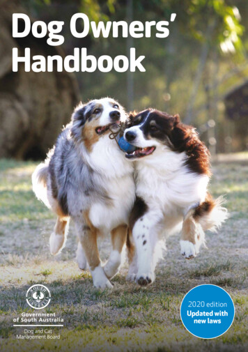
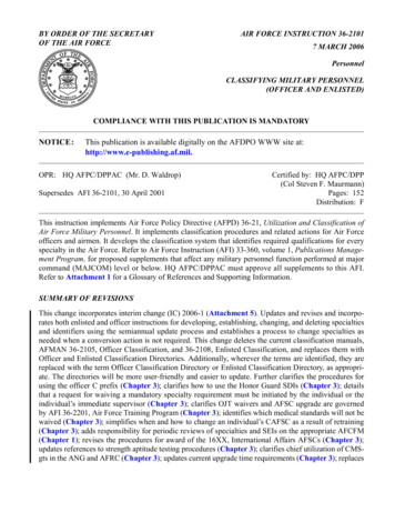
JULY 20182.3 NOTIONAL SITE2.3.A. Site Location, Orientation and AdjacenciesThe notional site plan diagram demonstrates key site development criteria. It is not asite-specific solution. The information represents the land requirements to constructthis facility and includes associated AT standoff and parking. Additional land may beneeded to comply with the stormwater management requirements of UFC 3-210-10Low Impact Development. Utilization of existing or shared parking is allowable andmay reduce the total acreage required for the facility. Adapt the requirements to thespecific site and location and comply with the applicable Installation Development Plan(IDP) and Area Development Plan (ADP) for facility siting.Several factors determine the most appropriate and cost-effective location for a facility.The availability and capacity of required utilities and the mass/scale of the facilityrelative to adjacent structures and noise issues must be analyzed.Emphasis must be placed on operation, function, and safety when siting the facility.Consider surrounding area noise will affect the Military Working Dog rest and also activedog noise during or between training could create a distraction for people working in thearea. The preferred location for this facility is away from runways, taxiways, small armsranges or any other areas where the time weighted overall sound pressure level for any24 hour period exceeds 75 adjusted decibels. Also avoid any low-lying areas that couldlead to infestations of mosquitos, ticks, rodents and other external parasites. Analyzeand comply with clearances, building setback restrictions, and line of sight restrictions. Ifunavoidable, incorporate visual and noise barriers such as berms/ screen walls tomitigate any potential distractions.The approximate project area required for the Military Working Dog Facility is 1.5 acres,which includes antiterrorism/force protection standoff and parking. Utilization of existingor shared parking is allowable and may reduce the total acreage required for the facility.2.3.B. ParkingParking will be as required by the programming documents, but at a minimum must beprovided to accommodate 40 percent of the largest shift of assigned personnel.2.3.C. Vehicular and Pedestrian CirculationConvenient and safe vehicular access and circulation must be provided for personalvehicles and essential services, including operations, maintenance, deliveries, dumpster/recycling collection, and emergency services.Locate sidewalk networks to provide convenient and safe pedestrian circulation fromexisting circulation elements of the project site to the new parking areas and doors ofthe facility. Sidewalk width must accommodate maintenance and emergency servicesrequirements.2.3.D. Notional Site PlanSee Next Page for Image8
JULY 20189
JULY 20182.4 BUILDING DESIGN2.4.A. General ConsiderationsGeneral considerations of the facility design are centered on: The Kennel and the associated Administration areas based on the number ofdogs to be trained and required trainers / handlers.The functional relationships between the modules as well as within the modulesThe general personnel flow requirements within the facility.Daily shift personnel enter the facility from the administrative side of the building andcontinue to the Support or Kennel areas of the building as needed.The Building Support Module needs exterior access. The outdoor support spaces needto be located with proximity to the facility as well as the obedience course.Other general considerations include: Mitigating Noise and Smell from Kennel Areas.Obedience CourseSite Limitations2.4.B. Building ConfigurationThe building should be configured for future expansion or reconfiguration. The generalsize of the building is based on the number, type and/or size of the primary module(s)required for this type of facility. The general configuration of the building is a linear typeconfiguration with the Administrative/Support located at the entrance of the facility withsupport areas located at the back end of the facility. The size of the following module isaffected by the quantity of animals supported: Kennel2.4.C. Interior/Exterior RelationshipsThe Military Dog Facility will have access to POV and Visitor parking. There will be asingle point of entry to facility with support spaces on opposite sides of the facilitycorridor.2.4.D. Functional Area RequirementsFacility Modules Adjacency Diagrams & Conceptual Axonometric Layout(s)The composite diagram(s) represent ways to conceptually assemble the functionalareas (modules) into a cohesive whole. Individual modules are represented bydifferent colors.Spaces and rooms that are integrally related with a specific functional connection oroperational flow are grouped into a module. Modules and the associated room datasheets identify specific criteria and additional detail for each functional area of the10
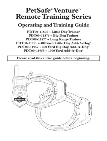
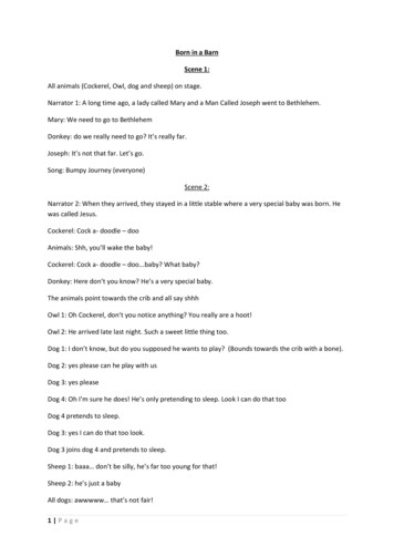
JULY 2018facility as outlined in the Interactive Programming Sheet located at the end of thedocument.The modules are a grouping of functional spaces and represent “Lego blocks” to beused in a “kit-of-parts” design approach. Use the fixed modules as pre-assembledpieces of the facility “puzzle”. Assemble them to comply with the required adjacenciesindicated in the diagrams and module plans.Modules must be used as shown in this Standard Design to the greatest extent possibleand must not be deconstructed or altered except as indicated herein. The intent of theStandard Design criteria is to avoid manipulation of the composition, functionalrelationships, adjacencies, and module sizes. Modules contain fixed attributes andmust not be changed arbitrarily. Modules may be rotated, flipped, and/or mirrored toaccommodate an overall composition or site issue, but this must not be done arbitrarilyand should occur only when necessary.Some modules are linked to space requirements that increase or decrease in sizebased on the personnel count and equipment for a particular mission. In these cases,increase or decrease the size of the module to match the revised scope calculation.This may sometimes require minor adjustments in other adjacent modules so that theyproperly fit together to create a constructible facility floor plan. Spaces must complywith any critical dimensions indicated on module plans. Manipulate as few modules aspossible to create a constructible facility. The resulting composite plan must respect theestablished modules adjacencies and must not exceed the authorized project scope.Functional Adjacency DiagramThe following Functional Adjacency Diagram forms the basis of design for the MilitaryWorking Dog Facility Standard Design. The Facility is programed around the KennelArea which is located at the ‘back’ end of the facility with support spaces that includethe exam room, surgery room, food storage and preparation and tack room. TheAdministration, Common Use and Toilet/Shower/Locker Modules, are located at thefront end of the facility. This Facility Adjacency Diagram as well as the modules is theAir Force approved Standard Design.11
JULY 201812
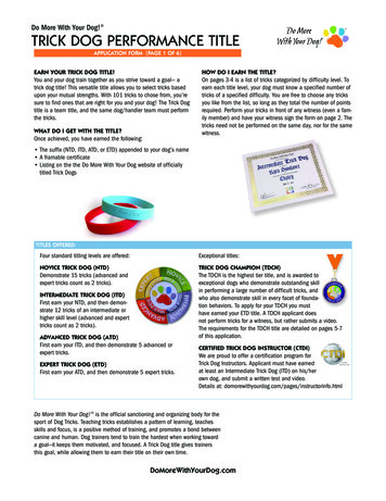
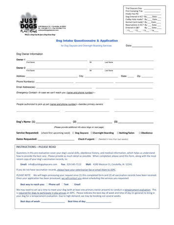
JULY 2018MODULE A – ADMINISTRATION MODULEFunction and AdjacencyThe Administration Module consists of a Kennel Master Office, Handler Office, andTrainer Office. This module is intended to be the primary entrance for the facility andsupports all administrative purposes for the facility.Figure 2-A.1 Module A Adjacency Diagram13
JULY 2018AdministrationFigure 2-A.2 Module A Floor Plan & Axonometric14
JULY 2018MODULE B – SPECIAL USEFunction and AdjacencyThe Special Use Module includes the Food Storage / Food Preparation Room, TackRoom, Exam Room and Surgery Room. The Food Storage/ Preparation room shouldbe located near the Kennel area and have an exterior entry. The tack room is a storagearea for staff training equipment and should also be located near the kennel area. TheExam Room Module includes an exam room and an isolation kennel space for sickdogs. The exam room and surgery room should be located with proximity to the kennelarea and to the food storage / preparation areas.Figure 2-B.1 Module B Adjacency Diagram15
JULY 2018Special UseFigure 2-B.2 Module B Floor Plan & Axonometric16
JULY 2018MODULE C – COMMON USE / SUPPORTFunction and AdjacencyThe Common Use/Support Module includes the TA-50 Locker Room and the MultiPurpose Room. The TA – 50 locker room should be sized to accommodate lockers forall staff / personnel in the facility. The Multi-purpose room can serve as a combinationconference room, classroom and break room. A recycling area is required in this room.Figure 2-C.1 Module C Adjacency Diagram17
JULY 2018Common Use / SupportFigure 2-C.2 Module C Floor Plan & Axonometric18
JULY 2018MODULE D – KENNELFunction and AdjacencyThe Kennel Module is the area where dogs will be housed when not in training or onduty. This module can be modified or scaled based on the training, quantity of dogs andhousing requirements of each base location. The conceptual basis of design kennelarea will include a Dog House, Interior Kennel and Exterior Kennel, Interior & Exteriorcorridor (“Dog Run”) as well as a dry storage room and wet storage room. This modulemust be located at the ‘back’ end of the facility. Kennel variations can include either anattached or detached layout that may or may not include a dog house or exterior kennel.Additionally, the layout can be arranged in either a double loaded or single loadedorganization. When siting allows, the detached layout should be located a minimumdistance of 20’-0” from the primary facility to help mitigate the impact of noise andodors.Figure 2-D.1 Module D Adjacency Diagram19
JULY 2018KennelFigure 2-D.2 Module D Floor Plan & Axonometric20
JULY 2018MODULE E– TOILET, SHOWER, LOCKERFunction and AdjacencyThe Toilet Module consists of a male toilet room, a female toilet room and janitor room.This module should be located near the administrative module and near the front of thefacility. Each toilet room will include a toilet, shower with locker area, and a janitor’scloset. The plumbing fixture count in the Standard design plan is approximate andactual plumbing fixture count shall be as required per actual occupancy count and asrequired in International Plumbing Codes, latest edition, Chapter 29.Figure 2-E.1 Module E Adjacency Diagram21
JULY 2018Toilet, Shower, LockerFigure 2-E.2 Module E Floor Plan & Axonometric22
JULY 2018MODULE F – BUILDING SUPPORTFunction and AdjacencyThe Building Support Module consists of a mechanical room, electrical room, andcommunications room. All rooms will have exterior access (with the exception of thecommunications room, which may have interior access). These modules will be locatedon the exterior wall adjacent to the utility courtyard and accessible for maintenance.Figure 2-F.1 Module F Adjacency Diagram23
JULY 2018Building SupportFigure 2-F.2 Module F Floor Plan & Axonometric24
JULY 2018MODULE G – OUTDOOR SUPPORTFunction and AdjacencyThe Outdoor Support Module includes an outdoor storage area, dog break area,optional explosive storage area and the obedience course.Figure 2-G.1 Module G Adjacency Diagram25
JULY 2018Outdoor SupportFigure 2-G.2 Module G Floor Plan & Axonometric26
JULY 20182.4.E. Room Data SheetsSpecific requirements for each room, space, or area are provided on room data sheetsthat correspond to their respective color-coded Modules, basis of design FunctionalAdjacency Diagram as well as the Interactive Programming Worksheet. Informationcontained on the data sheets defines the functional and physical requirements foreach of the spaces within the facility type and are generally minimum requirementsand must be modified as required for specific unique situations/scenarios as deemappropriate by the USAF.27
JULY 2018Figure 2-A.3.1 Kennel Master Room Data SheetINDEXA1Description/UsageThe kennel master office serves as the nerve center for the complex. The kennel mastermaintains kennels, ensures MWDs are properly cared for, and handlers areknowledgeable of responsibilities. Ideally the office should be located at the front of theadministrative area with exterior windows that view the entry gate to the complex. Thisoffice requires a secure closet within the space.Ceiling Height9'-0" minimumExterior – Aluminum framed, insulated fixed, blast resistant; Meeting daylightingrequirements of UFC 1-200-02WindowsDoorsFinishesTypeHollow metal, 3' x 7'Security/HardwareKeyed lock setView Panels/Kick PlatesView panels, 5” x 20”Kick plates on both sides of doorsWallsGypsum board - paintedFloorSealed concrete, stained concrete, tile or carpet tileBaseResilient or tileCeilingAcoustical Ceiling TilePlumbingN/AHVACHeating, ventilation, air conditioningFire Protection / Life SafetyWet pipe sprinkler systemPowerPer UFC 3-520-01LightingPer UFC 3-530-01CommunicationTele.One per nishings / Equipment / CaseworkSpecial RequirementsPer UFC 3-450-01 for noise controlLockable closet for storage of supplies. Desk, chair, visitor seating (two), four drawer filecabinet, and bookcase. Computer, printer, fax/copierN/A28
JULY 2018Figure 2-A.3.2 Trainer Room Data SheetINDEXA2Open office with 5 workstations. Trainers conduct patrol and explosive/narcotic detectiontraining including training on the obstacle course.9'-0" minimumExterior – Aluminum framed, insulated fixed, blast resistant; Meeting daylightingrequirements of UFC 1-200-02Description/UsageCeiling HeightWindowsDoorsFinishesTypeHollow metal, 3' x 7'Security/HardwareKeyed lock setView Panels/Kick PlatesView panels, 5” x 20”Kick plates on both sides of doorsWallsGypsum board - paintedFloorSealed concrete, stained concrete, tile or carpet tileBaseResilient or tileCeilingAcoustical Ceiling TilePlumbingN/AHVACHeating, ventilation, air conditioningFire Protection / Life SafetyWet pipe sprinkler systemPowerPer UFC 3-520-01LightingPer UFC 3-530-01CommunicationTele.One per nishings / Equipment / CaseworkSpecial RequirementsPer UFC 3-450-01 for noise controlFive (5) workstations; Desk, chair, four drawer file cabinet for each trainer, and a commonbookcase. Computer, printer, copier and one 4 x 8-foot dry erase board.N/A29
JULY 2018Figure 2-A.3.3 Handlers Room Data SheetINDEXA3Open office for minimum of 10 handlers with workstations and space for documentationstorage.9'-0" minimumExterior – Aluminum framed, insulated fixed, blast resistant; Meeting daylightingrequirements of UFC 1-200-02Description/UsageCeiling HeightWindowsDoorsFinishesTypeHollow metal, 3' x 7'Security/HardwareKeyed lock setView Panels/Kick PlatesView panels, 5” x 20”Kick plates on both sides of doorsWallsGypsum board - paintedFloorSealed concrete, stained concrete, tile or carpet tileBaseResilient or tileCeilingAcoustical Ceiling TilePlumbingN/AHVACHeating, ventilation, air conditioningFire Protection / Life SafetyWet pipe sprinkler systemPowerPer UFC 3-520-01LightingPer UFC 3-530-01CommunicationTele.One per deskDataNIPRCCTVN/ACATVN/ASecurityN/AAcousticalPer UFC 3-450-01 for noise controlFurnishings / Equipment / CaseworkTen (10) workstations, file cabinets. Computers and printer.Special RequirementsN/A30
JULY 2018Figure 2-B.3.1 Tack Room Data SheetINDEXB1Description/UsageThe tack room is for storage of MWD equipment, such as body suits and portable kennelsfor transportation.Ceiling Height9'-0" minimumWindowsN/ADoorsFinishesTypeHollow metal, 3’-0” x 7’-0”Counter shutter – 6’ x 4’, manually operatedSecurity/HardwareKeyed lock setView Panels/Kick PlatesView panels, 5” x 20”Kick plates on both sides of doorWallsGypsum board - paintedFloorSealed concrete, Stained concrete, tileBaseResilient or tileCeilingGypsum board – painted or exposed structure - paintedPlumbingSinkFire Protection / Life SafetyWet pipe sprinkler systemPowerPer UFC 3-520-01LightingPer UFC 3-530-01CommunicationTele.One per RoomDataNIPRCCTVN/ACATVN/ASecurityN/AAcousticalPer UFC 3-450-01 for noise controlFurnishings / Equipment / CaseworkN/ASpecial RequirementsRequirements include 12 linear feet of 36 in by 18 in by 36 in deep shelves, a 24 inhanging space with hooks and 6 linear feet of 18 in by 18 in by 12 in shelves.31
JULY 2018Figure 2-B.3.2 Food Storage & Preparation Room Data SheetINDEXB2Ceiling HeightThe food storage room is for bulk storage of normally a 30-day supply of food for thedogs. Also working/ preparation space for food for dogs.9'-0" minimumWindowsNo Windows /HardwareHollow metal, pair 3' x 7'View Panels/Kick PlatesNo view panelsKick plates both sides of doorWallsCMU or gypsum board - paintedFloorSealer hardenerBaseResilientCeilingExposed structure - paintedKeyed lock setPlumbingHVACHeating and ventilation. Exhaust directly outdoors through roof.Fire Protection / Life SafetyWet pipe sprinklerPowerPer UFC 3-520-01LightingPer UFC 3-530-01CommunicationTele.One per Furnishings / Equipment / CaseworkN/ASpecial RequirementsTemperature and humidity control equivalent to the office area are required in thisroom to control food spoilage. Countertop, base and wall cabinets for food storage andpreparation.32
JULY 2018Figure 2-B.3.3 Exam Room Data SheetINDEXB3Description/UsageRoom for dog treatment and exams. Also for quarantine of sick dogs or recovery area.Ceiling Height9'-0" minimumWindowsNo Windows PermittedDoorsFinishesTypeHollow metal, 3'x7'Security/HardwareKeyed lock setView Panels/Kick PlatesNo view panelsKick Plates both sides of doorWallsGypsum board - painted, ceramic tileFloorPorcelain tile or quartz epoxyBasePorcelain tile or quartz epoxyCeilingGypsum board - paintedPlumbingFloor drainHVACHeating, ventilation, air conditioning. Exhaust directly outdoors.Fire Protection / Life SafetyWet pipe sprinkler systemPowerPer UFC 3-520-01LightingPer UFC 3-530-01CommunicationTele.One per RoomDataNIPRCCTVN/ACATVN/ASecurityN/AAcousticalPer UFC 3-450-01 for noise controlFurnishings / Equipment / CaseworkCeiling Mounted Exam room Light, Walk on Platform Scale, Stationary Exam tableSpecial RequirementsWater resistant gypsum board throughout.33
JULY 2018Figure 2-B.3.4 Surgery Room Data SheetINDEXB4Description/UsageRoom for dog medical procedures and operationsCeiling Height9'-0" minimumWindowsNo Windows PermittedDoorsFinishesTypeHollow metal, 3'x7'Security/HardwareKeyed lock setView Panels/Kick PlatesNo view panelsKick Plates both sides of doorWallsGypsum board - painted, ceramic tileFloorPorcelain tile or quartz epoxyBasePorcelain tile or quartz epoxyCeilingGypsum board - paintedPlumbingFloor drainHVACH
The primary function of this Military Working Dog Facility is to provide a facility that fully supports the mission with a flexible state-of-the-art building. The facility supports weapons systems and communications technology within a standalone facility . The facility is comprised of Dog Kennel, Dog Training/Support and Administrative/Support