Transcription
Cisco Mobility Services Engine - Context Aware Mobility Solution Deployment Guide - . Page 1 of 60Products & ServicesCisco Mobility Services Engine - Context Aware Mobility Solution Deployment GuideDocument ID: sComponents UsedConventionsBackground InformationSection 1: Solution OverviewTerminologyTechnology Background InformationRSSI (Received Signal Strength Indication)TDOA (Time Difference of Arrival)Active RFID TagsSection 2: Plan and Setup of Your Context Aware NetworkAccess Point PlacementTracking Optimized Monitor Mode (TOMM)AP and Antenna PlacementSignal AttenuationSurveyance of Multi-Floor Buildings, Hospitals, and WarehousesLocation Rails and RegionsCreate a Mask in the System ManagerCells in Context-Aware Engine for TagsInitial Operation for Cells ConfigurationCalibration – Context Aware Engine for ClientsExciter (Chokepoint Trigger) TechnologyConsiderations for Deploying Context Aware with Existing Data and VoiceServicesGeneral Guidelines – TDOAWired LocationSection 3: Validation and Improvement of Your Context Aware NetworkWCS Accuracy ToolLocation Readiness ToolContext Aware – System PerformanceRFID Tag and WLC Configuration/TuningWCS and MSE Configuration and TuningTroubleshootingSection 4: Final ChecklistHardware RequirementsSection 5: Frequently Asked Technical QuestionsAppendix A: MSE SetupAdd the MSE to WCSAppendix B: WLC and MSE CommandsAppendix C: MSE Upgrade from 5.X to 6.0Appendix D: MSE Database RestoreCisco Support Community - Featured ConversationsRelated InformationIntroductionThe purpose of this document is to provide configuration and deployment guidelines, as well as troubleshooting tips andanswers to frequently asked technical questions for those that add the Cisco Mobility Services Engine (MSE) and runContext Aware Services to a Cisco Unified WLAN. The purpose of this document is to: Explain the various elements and framework for the Cisco Mobility Solution Provide general deployment guidelines to deploy Cisco Mobility SolutionThis document does not provide configuration details for the MSE and associated components. This information is providedin other documents, and references are provided. Refer to the Related Information section for a list of documents about theconfiguration and design of Context Aware Mobility Services. Adaptive wIPS configuration is also not covered in thisdocument.PrerequisitesRequirementsThere are no specific requirements for this document.Components UsedThis document is not restricted to specific software and hardware versions.ConventionsRefer to Cisco Technical Tips Conventions for more information on document conventions.Background InformationThe Cisco MSE provides the ability to track the physical location of Network Devices, both wired and wireless, usingwireless LAN controllers (WLCs) and Cisco Aironet Lightweight Access Points (LAPs). This solution allows a customer totrack any Wi-Fi device, including clients, active RFID tags, and rogue clients and access points (APs). It was designed withthese requirements in -cams-guide.xml?convertPaths 13/7/2012
Cisco Mobility Services Engine - Context Aware Mobility Solution Deployment Guide - . Page 2 of 60 Manageability—Cisco Wireless Control System (WCS) is used to administer and monitor the MSE. Moreover, theMSE integrates directly into the wireless LAN architecture, which provides one unified network to manage instead ofmultiple disparate wireless networks. Scalability—The Cisco MSE series can simultaneously track up to 18,000 network elements. The WCS can managemultiple Mobility Services Engines for greater scalability. The controller, WCS, and MSE are implemented throughseparate devices to deliver greater scalability and performance. Security—The MSE, WCS, and wireless LAN controller provide robust secure interfaces and secure protocols toaccess data. The MSE records historical location information that can be used for audit trails and regulatorycompliance. Open and standards based—The MSE has a SOAP/XML API that can be accessed by external systems andapplications that can leverage location information from the MSE. Easy deployment of business applications—The MSE can be integrated with new business applications such asasset tracking, inventory management, location-based security, or automated workflow management.This document is divided into five sections:1. Solution Overview2. Planning and Setup of Wi-Fi Network for Context Aware3. Validation and Improvements of Context Aware Network4. Troubleshooting5. Final Check ItemsSection 1: Solution OverviewContext Aware Service (CAS) provides the capability for a Wi-Fi 802.11a/b/g/n network to determine the location of aperson or object with an active Wi-Fi device, such as a wireless client or active RFID tag and/or associated data that can bepassed by the end point through the wireless infrastructure to an upstream client. When a Cisco Mobility Service Engine(MSE) is added to a Cisco Unified Wireless Network (CUWN) with an appropriately licensed version of WCS, it assumesresponsibility for several important tasks: Execution of positioning algorithms Maintenance of calibration information Trigger and dispatch of location notifications Process of statistics and historical location Depository for geographical information, maps, and all wireless devicesWCS is the management system that interfaces with the MSE and serves user interface (UI) for the services that the MSEprovides. Although it is possible to access the MSE directly through SSH or a console session for maintenance anddiagnostic purposes, all operator and user interaction with the MSE is typically performed through WCS (for management)or a third-party location client application.TerminologyWith the Cisco centralized wireless LAN architecture and Context-Aware Location Services, administrators can determinethe location of any 802.11-based device, as well as the specific type or status of each device. Clients (associated, probing,etc.), rogue access points, rogue clients, and active tags can all be identified and located by the system. This information ismade available through the API within seconds of an event occurrence and can be retained by the MSE database forhistorical lookup or security audits.Mobility Services Engine (MSE): MSE supports a suite of mobility services programs. Designed as an open platform, theMSE supports mobility services software in a modular fashion with various configuration options based on network topologyand the types of services required. The value of the MSE is delivered through the various mobility services applications.Cisco supports existent and future software that include these: Context-Aware Services: These programs capture and integrate into business processes detailed contextualinformation about such things as location, temperature, availability, and applications used. Context-awareapplications feature a wide range of location options that include real-time location, presence detection, chokepointvisibility, and telemetry. Support for enhanced received signal strength indication (RSSI) and time difference ofarrival (TDoA) technology delivers greater scale accuracy and performance for a broad range of environments.Context Aware software consists of two major components: Context Aware Engine for Clients: The Cisco location engine (RSSI) is used to track Wi-Fi clients, rogueclients, rogue APs, and wired clients. Context Aware Engine for Tags: The partner (AeroScout) location engine (both RSSI and TDOA) is used totrack Wi-Fi active RFID tag.Third-party applications are supported through the MSE API. Adaptive Wireless Intrusion Prevention System (wIPS): wIPS software provides visibility and comprehensivethreat prevention for the mobility network through monitoring, alerts, classifying, and remediation of wireless andwired network vulnerabilities.Network Mobility Services Protocol: Cisco-defined protocol that is used for secure communication between the WLC ams-guide.xml?convertPaths 13/7/2012
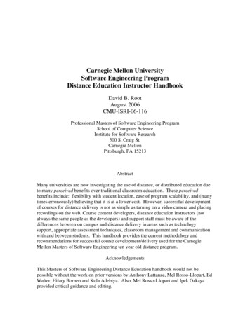
Cisco Mobility Services Engine - Context Aware Mobility Solution Deployment Guide - . Page 3 of 60MSE.Wireless Control System (WCS): Wireless network management system developed and supported by Cisco Systems.Includes these capabilities: WLAN configuration WLAN performance monitoring Reporting (real-time and historical) Graphical view of network (wireless LAN controllers, access points, clients and tags)Wireless LAN Controller (WLC): The CUWN architecture centralizes WLAN configuration and control into a device calleda WLAN Controller (WLC). This allows the entire WLAN to operate as an intelligent network that uses wireless as theaccess medium to support advanced services, unlike legacy 802.11 WLAN infrastructures that are built from autonomous,discrete access points. The CUWN simplifies operational management by collapsing large numbers of managed endpoints—autonomous access points—into a single managed system comprised of the WLAN controller(s) and itscorresponding, joined access points.In the CUWN architecture, APs are “lightweight,” which means that they cannot act independently of a WLC. APs aretypically “zero-touch” deployed, and no individual configuration of APs is required. The APs learn the IP address of one ormore WLC through a controller discovery algorithm and then establish a trust relationship with a controller through a “join”process. Once the trust relationship is established, the WLC pushes firmware to the AP, if necessary, and a run-timeconfiguration. APs do not store a configuration locally.Clients: All devices associated with controller-based, lightweight access points on a wireless network.Rogue Access Point: Any access point that is determined not to be part of the wireless LAN mobility group that detected it.This consists of all non-system access points within RF range of a lightweight access points, which includes those on thewired network or those on another wired network (such as an access point of a neighbor). Because all lightweight accesspoints use a hash as part of the beacon frame with a special key, even spoofed infrastructure access points are identified asrogue access points rather than mistaken to be legitimate access points flagged in WCS as spoof access points.Rogue Clients: All devices that are associated to rogue access points.Active RFID Tags: Wi-Fi device that can be detected and located on a Wi-Fi network. There is wide variety of Wi-Ficompatible tags available in the market. Tags offer a range of features that include telemetry, such as motion andenvironmental data such as temperature and humidity, call buttons, indoor and outdoor operation, intrinsically safe versions,and flexible mounting options.The MSE provides the ability to track up to 18,000 devices (tags, clients, and rogue clients/APs). Figure 1 is an example ofa floor map as shown in the WCS, and displays tags, clients, rogue clients and rogue APs. The floor map illustrates thescale and variety of classes of devices that can be tracked by the MSE. WCS provides the capability to define searchparameters to display only in a subset of devices. For example, a biomedical user can want to see only infusion pumps andEKG machines named with friendly identifiers rather than rogue devices or devices with cryptic MAC or IP addresses.Figure 1: WCS Floor Map with Tracked DevicesClient:Tag:Rogue AP (red malicious, green friendly, gray unclassified)Rogue mse-cams-guide.xml?convertPaths 13/7/2012
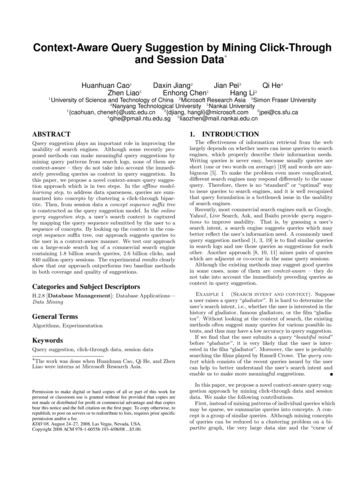
Cisco Mobility Services Engine - Context Aware Mobility Solution Deployment Guide - . Page 4 of 60Technology Background InformationThere are two technologies that are used to track Wi-Fi devices with the Cisco Mobility Solution: RSSI (Received Signal Strength Indication) TDOA (Time Difference of Arrival)Details on these technologies are provided in the Wi-Fi Location-Based Services 4.1 Design Guide.RSSI (Received Signal Strength Indication)RSSI is the measured power of a received radio signal. The packets transmitted by any wireless device are received atmultiple APs (provided that those APs listen on the channel on which the frame was transmitted). The APs forward thesepackets to the wireless LAN controller along with the correspondent RSSI information measured at the AP. The wirelessLAN controller aggregates this information on a per device basis from different APs. This data is forwarded to the MSEthrough NMSP. The Context Aware Services that reside on the MSE use the RSSI data received from one or more WLCs todetermine the location of a wireless device.RSSI is usually preferred for indoor or low ceiling environments, which can result in reflection of the signals. Unlike TDOA,RSSI does not require exact time synchronization amongst APs. With the measured RSSI values from different APs, theprobability of the location of a device is calculated at different points on the floor. Based on this probability, the location isreturned as the estimated location.TDOA (Time Difference of Arrival)When you track tags in outdoor and outdoor-like environments, such as are found in indoor high-ceiling environments, thetime difference on arrival (TDOA) mechanism is the preferred method to determine device location. With TDOA, the locationof a WLAN device is determined based on the difference in time of arrival (TOA) of the signal that it transmits as seen bythree or more time-synchronized Wi-Fi TDOA receivers. The time of arrival data is collected and reported to the ContextAware Engine for Tags that reside on the MSE, which computes the time-differences-of-arrival between multiple pairs of WiFi TDOA receivers. The time required for a given message to be received by different Wi-Fi TDOA receivers is proportionalto the length of the transmission path between the mobile transmitting device and each TDOA receiver. This mechanism ofcalculation device location requires time synchronization between the Wi-Fi TDOA receivers.In order to compute a position accurately, this method requires a set of at least three Wi-Fi TDOA receivers. The distancebetween Wi-Fi TDOA receivers is relatively larger than the distance between Access Points that are required for indoorRSSI positioning. As with RSSI positioning, this method relies on unidirectional communication (tag transmitting notificationframe, no association required).Refer to the Context-Aware Service Software Configuration Guide.Active RFID TagsCCX-compliant active RFID tags are detected on a Wi-Fi network based on tag notification frames that are sent by the tagand received by an 802.11 AP. The tag notification frame rate can be programmed based on the specific use case scenario.Typically, tags are configured to transmit tag notification frames every 3-5 minutes to optimize frequent location updates andbattery life.The call button feature provides the ability to trigger events based on push button on the tag. This enables advancedfunctionality, such as emergency reporting or parts replenishment. Some tags provide more than one call button. Thesecond call button can be programmed for additional functionality.Tags can store pre-programmed messages that can be received by the wireless network infrastructure. A battery is used topower active tags, which provides up to four years of battery life. Battery life is dependent upon a number of tagconfiguration parameters that includes the frequency of tag notification frame transmission and repetition rate. Tags canreport on their battery level and alert when low. Tags can also have a built-in motion sensor to transmit tag notificationframes upon movement. This helps to conserve battery life when the tag is stationary; configure the tags to transmit lessfrequently when they do not move.There is another category of tags that add advanced sensor technology to accurately monitor the condition of an asset,such as its ambient temperature, in addition to other location and status information. These sensor tags use standard Wi-Finetworks to transport the asset location and sensor data and do not require dedicated or proprietary sensor networks.Wi-Fi RFID tags that are compliant with the Cisco Compatible Extensions (CCX) for Wi-Fi Tags specification can optionallypass tag telemetry information to the location-aware Cisco UWN as part of their tag message payload. Telemetryinformation is received by access points and collected by the WLCs. At MSE startup, the MSE subscribes for all the servicein which it is interested, such as the measurements for tags. The WLC continues to send the MSE notifications at the end ofeach aggregation cycle.Telemetry information is transmitted from a CCX-compatible tag and is received by one or more APs and/or locationreceivers, that is, Wi-Fi TDOA receivers, which, in turn, pass the telemetry information to their respective registered WLANcontrollers. If the tags are configured to send multiple frame copies (or bursts) per channel, the controller eliminates anyduplicate tag telemetry and passes the distilled telemetry values to the MSE. The database in the MSE is updated with thenew telemetry information and makes it available to location clients through the SOAP/XML API.In the case of a tag that passes telemetry value, NMSP is designed to efficiently transport telemetry values from multipletags in a similar fashion. Telemetry traffic from multiple tags is aggregated by the WLC with each NMSP endpoint capableof performing NMSP frame fragmentation and reassembly if required. All tag data can be included in the northboundnotifications, which includes telemetry, call buttons, chokepoint encounters, etc.System ArchitectureThe MSE integrates with the Cisco centralized wireless LAN architecture as shown in Figure 2. The MSE sits out of thedata path of the wireless LAN (see diagram) and receives data from the WLC through NMSP. WCS is used to configure theMSE. Once configured, the MSE is self 1/mse-cams-guide.xml?convertPaths 13/7/2012
Cisco Mobility Services Engine - Context Aware Mobility Solution Deployment Guide - . Page 5 of 60Figure 2: System ArchitectureWhen you deploy the Context Aware solution, consideration must be given to the type of devices tracked and the maximumdevice count. You can track any of the five device types (Wi-Fi clients, active RFID tags, rogue clients, rogue APs, or wiredclients) to be configured individually or for simultaneous tracking.One MSE can be managed by only one WCS, that is, a single MSE cannot be managed by multiple WCS instances, but asingle WCS can manage multiple MSEs. When the number of devices to be managed exceeds the capacity of a singleMSE, you need to deploy multiple, independent MSEs. The ability to deploy multiple MSEs for scaling applies to all servicescurrently supported on MSE. The maximum number of devices that can be tracked by one Cisco MSE 3350 is 18,000devices (combination of Wi-Fi clients, active RFID tags, rogue clients, rogue APs, and wired clients) as part of ContextAware Service. The Cisco MSE 3310 can track up to 2,000 devices. When the number of devices to be managed exceedsthe capacity of a single MSE box, multiple, independent MSE appliances need to be deployed. This can require MSEs onspecific controllers, especially on large campuses where roaming of clients or assets can cross different physical buildingsor domains. In this instance, controllers can communicate with a maximum of 10 MSE appliances.Cisco LAPs operate in a unique dual mode that detect devices both on the channels where they service clients and also onall other channels if they periodically background scan while still provide data access to their wireless clients. The gatheredraw location data is then forwarded from each access point to its associated WLC through the LWAPP or standards-basedCAPWAP protocol. Data is transported between the wireless LAN controller and the MSE through a secure NMSPconnection.Cisco WCS is used to manage and configure the MSE, and it can also become the visual front-end of the MSE to displayWi-Fi devices that are tracked. All device (wired and wireless) details and specific historical location information can beaccessed with the MSE northbound API. WCS uses this interface to visualize location information, as well as view andconfigure Context Aware parameters.The Cisco Mobility Solution consists of two location engines with a single unified application programming interface (API): Context Aware Engine for Clients (Cisco engine) Context Aware Engine for Tags (partner engine)The Context Aware Engine for Clients is an RSSI-based solution and is ideal to track Wi-Fi client devices in indoor spaces,for example, offices, hospitals, or other low-ceiling environments. This engine ships by default on all Cisco MSE servers. Inaddition to the Cisco MSE, customers need to purchase two additional components for client tracking: Client tracking license for the MSE with appropriate client count Cisco WCS PLUS with locationThe Context Aware Engine for Tags has the ability to use both an RSSI and TDOA-based engine and is intended to beused when you track Wi-Fi devices in indoor, low-ceiling (RSSI), indoor high-ceiling (TDOA), and outdoor (TDOA)environments. This engine is also installed by default on all MSE platforms and is license enabled. Customers need topurchase these additional components for client tracking: Tag tracking license for the MSE with appropriate tag count (TDoA or RSSI) Wi-Fi TDoA location receivers (if and when required) LR license for each Wi-Fi TDoA receiver Cisco WCS PLUS with locationWhen a Cisco MSE is added to a Cisco Unified Wireless Network, the MSE assumes responsibility for several importanttasks: Execution of positioning algorithms Maintenance of calibration information Triggering and dispatch of location 7571/mse-cams-guide.xml?convertPaths 13/7/2012
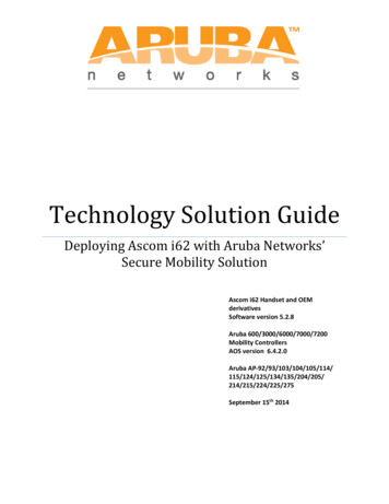
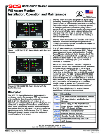
Cisco Mobility Services Engine - Context Aware Mobility Solution Deployment Guide - . Page 6 of 60 Processing of statistics and historical locationWCS is the management platform for the MSE servers and as the user interface (UI) for the services that the MSE provides.The MSE is accessed directly through SSH or a console session for maintenance and diagnostic purposes. All operator anduser interaction with the MSE is usually through WCS.The integration of a Cisco MSE into a Cisco Unified Wireless Network architecture immediately enables improvements tobase-level location capabilities. Included, are these improvements:Scalability — If you add a Cisco MSE, it increases the scalability of the Cisco UWN from on-demand tracking of a singledevice at a time to a maximum tracking capacity of up to 18,000 simultaneous devices (WLAN clients, RFID tags, rogueaccess points, and rogue clients) per MSE. For deployments that require support of greater numbers of devices, additionalMSE appliances can be deployed and managed under one or more WCS servers.Historical and statistics trending —The MSE records and maintains historical location and statistics information for clientsand tags. This information is available for viewing through WCS or with third-party location clients. This historical informationcan be used for location trending, asset loss investigation, RF capacity management, and facilitation of network problemresolution.Historical parameters can be configured in WCS as shown in Figure 3.There are several variables that impact the amount of historical data that can be stored on the MSE: average number ofelements that move, average distance covered every time there is a movement, information transitions, telemetryinformation from tags, etc.By default, 30 days of historical data are stored in the MSE.Figure 3: Configuring History ParametersThese are important points to note about location history:1. The history tracking must be enabled (as shown) to retrieve any history information about an element.2. The number of days of history and pruning time must be properly chosen (see screen shot).3. Although the number of days to save history is not limited on the UI, the history stored on the server is limited by thedisk space and performance impact on the overall system.4. The history of an element is recorded only if these occur:a. It moves more than 10m or 30 feet.b. If the emergency or panic button is pressed on the tags.c. If the tag passes by an exciter.d. If the floor changes, that is, the element moves between floors.5. An element is declared “inactive” if it remains inactive for one hour. If it remains inactive for 24 hours, it is removedfrom the tracking table. Once the element is removed from the tracking table, then it is not possible to see element’shistorical location on the WCS monitoring page, although the element’s history is still there in the MSE for 30 days.Absent Data Cleanup Interval entry (see Figure 4), helps to control tracking table.Figure 4: Location 1/mse-cams-guide.xml?convertPaths 13/7/2012
Cisco Mobility Services Engine - Context Aware Mobility Solution Deployment Guide - . Page 7 of 60Logging every transition as an event for storage in the historical database and limiting the Location History table to 10million rows for performance reasons, Table 1 summarizes the number of days it takes to reach that limit. The greater thenumber of element transitions per minute, the greater the amount of disk space that is consumed. As per the table, it onlytakes 7.14 days to reach 10 million rows with 1000 transitions/minute. With the default of 30 days of historical data, 1000transitions/minute consumes excessive disk space since MSE does not delete historical data before the 30-day window hasbeen reached.Cisco recommends that you change the history parameter for devices that move frequently to a value of less than 30 days.Table 1: Location History Database LimitTransitions per minuteDays to hit 10 million 577009.928008.689007.7510007.14Chokepoint location — The MSE provides granular and deterministic localization based on the passage of an assetthrough a constrained physical area known as a chokepoint. Chokepoint triggers (also called “exciters”) located within theseareas and in proximity to tagged assets stimulate the tags with low-frequency (125 kHz) signaling. The RFID tags thentransmit the identity of the chokepoint trigger to the Cisco UWN infrastructure. The chokepoint information contained in thetag packet provides the MSE with information to override RF Fingerprinting location coordinates and assume the chokepointposition for a given duration. This proximity location accuracy can range from a radius of under one foot to over twenty feet(25 to 650cm), dependent upon the capabilities of the chokepoint trigger. Applications for chokepoint location vary fromgeneral-purpose uses, such as theft prevention of high value assets, to industry-specific process control events, such asthose used in manufacturing plants.Cisco Extensions for Wi-Fi Tags telemetry information and emergency notifications — Cisco has partnered with avariety of asset tag vendors to create an extensible specification for 802.11 Wi-Fi-based active asset tags. The CiscoCompatible Extensions (CCX) Wi-Fi Tag specification defines a common transmission format that tag vendors can use tointeroperate with the Context Aware Cisco UWN. This includes a baseline feature set that encompasses telemetry, tagtransmit power level, battery information, and advanced fields for emergency groups and chokepoints. The addition of anMSE allows customers to take advantage of these capabilities and benefits customers by providing the ability to "mix andmatch" compliant asset tags from different vendors in the same network. Currently, tag vendors have implemented CCXv1.Tag reference URL: http://www.cisco.com/web/partners/pr46/pr147/ccx wifi tags.html.Section 2: Plan and Setup of Your Context Aware NetworkThere are several guidelines that need to be followed when you deploy a wireless network that directly impact the level oflocation accuracy.Designing the Wireless LAN For Location And VoiceGeneral Guidelines – RSSIIn order to determine the optimum location of all devices in the wireless LAN coverage areas, consider access point densityand placement.Access Point /mse-cams-guide.xml?convertPaths 13/7/2012
Cisco Mobility Services Engine - Context Aware Mobility Solution Deployment Guide - . Page 8 of 60Proper placement of access points, or perhaps better, placement and type of antenna are several best practices that needto be met in order to experience a reasonable level of location accuracy. In many office wireless LANs, access points aredistributed mainly throughout interior spaces and provide service to the surrounding work areas. These access pointlocations have been selected traditionally on the basis of coverage: WLAN bandwidth, channel reuse, cell-to-cell overlap,security, aesthetics, and deployment feasibility. In a location-aware WLAN design, the requirements of underlying data andvoice applications must be combined with the requirements for good location fidelity. Dependent upon the particular site, therequirements of the location-aware Cisco UWN are flexible enough that the addition of location tracking to voice installationsalready designed in accordance with Cisco best practices, for example, possibly do not require extensive reworking. Rather,infrastructure already deployed in accordance with accepted voice best practices can often be augmented such that locationtracking best practice requirements are also met (such as perimeter and corner access point placement, for example)dependent upon the characteristics of the areas involved.In a location-ready design, i
answers to frequently asked technical questions for those that add the Cisco Mobility Services Engine (MSE) and run Context Aware Services to a Cisco Unified WLAN. The purpose of this document is to: Explain the various elements and framework for the Cisco Mobility Solution Provide general deployment guidelines to deploy Cisco Mobility Solution .