Transcription
K.Lee,G.C.Temes,F.Maloberti:"Noise- CoupledMulti- CellDelta- Systems,ISCAS2007,NewOrleans,27- ‐30May2007,pp.249- ‐252. erworksmustbeobtainedfromtheIEEE.
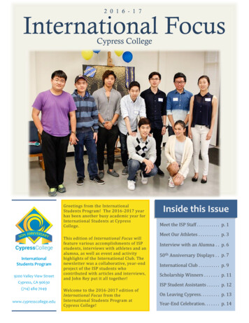
Noise-Coupled Multi-Cell Delta-Sigma ADCsKyehyung Lee and Gabor C. TemesFranco MalobertiSchool of Electrical Engineering and Computer ScienceOregon State UniversityCorvallis, Oregon, USA{leekye, temes}@eecs.oregonstate.eduDepartment of ElectronicsUniversity of Pavia27100 Pavia, oupled multi-cell delta-sigma ADCs arepresented. By providing quantization noise coupling betweenidentical delta-sigma ADCs, one can effectively raise the orderof the modulator. Cross-coupled noise injection also providesan efficient way to realize higher-order time-interleaved ADCs.H1zDACDACI. INTRODUCTIONIn an earlier paper [1], a multi-cell delta-sigma ADC wasintroduced to increase the robustness and programmability ofdelta-sigma ADC. The key of the method is the capability toraise the order of a noise transfer function by the crosscoupled injection of the quantization noise [2]. In this work,we propose two types of noise coupling in multi-cell deltasigma ADCs, and extend the operation to time-interleaved(TI) ADCs. The noise coupling between different modulatorcells (cross-enhanced delta-sigma ADC) or within eachmodulator cell (self-enhanced delta-sigma ADC) raises theeffective order of the modulator by one or more, dependingon the applied coupling filter, without aggravating thestability conditions. This is due to the statisticalindependence of quantization noise samples, which can beassumed under busy signal conditions and for multi-bitquantization. Then the injected noise acts as merely as dither,removing harmonic spurs. Thus, the stability condition of theoriginal modulator is preserved.z-1H2q2For duplicated modulators, the noise injection can becross-coupled as shown in Fig. 2. Since the coupledquantization noises are injected at the quantizer inputs, anyerror signals in the coupling branches will be suppressed bythe gain of the loop filter. Therefore, mismatches betweenDSM cells minimally affect cross-coupled delta-sigmaADCs. Self-enhanced delta-sigma ADCs do not suffer fromany mismatches between DSM cells.B. Second and higher-order noise couplingThe noise-coupling concept can be extended to higherorder coupling branches. By designing the coupling filterproperly, the order of modulator can be increased by two ormore. Second-order coupling can be implemented using atransfer function (2z-1-z-2) in the coupling branch, as shownin Fig. 3. The practical implementation of the cross couplingtypically uses added capacitors that worsen the feedbackfactor of the opamps used. The additional powerconsumption required is a small price to pay for a significantbenefit. Generally, the order of modulator can be increasedby n using a coupling block from DSM cell j to DSM cell i(Fig. 4) with a transfer functionFirst-order noise couplingThe order of a delta-sigma modulator (DSM) can beenhanced by self-coupled noise injection, shown in thescheme of Fig. 1. A delayed replica of the quantization erroris fed back into the modulator to be shaped by the noiseqvz-1DACFig. 1. DSM with self-coupled noise injection.This research was funded by the NSF Center for the Design ofAnalog/Digital Integrated Circuits (CDADIC).1-4244-0921-7/07 25.00 2007 IEEE.vdtransfer function (NTF). Since this increments the NTF by anextra (1-z-1) factor, the order of the modulator is increased byone. The structure can be duplicated, to provide the sum ofthe two outputs for signal processing, and their difference forcalibration purposes [3].NOISE COUPLING IN MULTI-CELL ADCSH1v2Fig. 2. Split DSM with cross-coupled noise injection.A.uvc-1uII.v1249
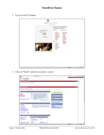
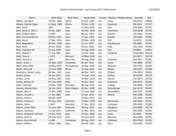
C1-z-2Fig. 4. Generalized split DSM with cross-coupled noise injection.v2B. Cross-coupled dual-channel TI delta-sigma ADCThe output signal of the dual-channel TI modulator withcross-coupled quantization noise injection is given by(1)k 0Ideally, cross-enhanced and self-enhanced couplingsprovide equivalent performance improvements. But selfenhanced noise coupling is not subject to injectedquantization noise leakage due to NTF mismatch, and ishence more suitable for programmable multi-cell DSMs.V ( z ) U ( z ) (1 z 1 ) NTF ( z 2 )Q( z ).(3)Unlike self-coupled noise injection, cross-coupled noiseinjection can enhance the order of NTF without introducingadditional out-of-band zeros. Therefore, it provides a 6 dBSNDR improvement compared to self-coupled noiseinjection. Observe that the scheme of Fig. 5 with loop filtersH(z2) z-2/(1-z-2) gives an NTF (1 z-1)·(1-z-1)2. A problemin the implementation of the scheme of Fig. 5 is thecombination of many analog signals before the quantizer.However, it is possible to move the point of noise injectionto the input of the H(z2) block, as shown in Fig. 6, whereH(z2) was split into a double delay and a 1/(1-z-2) block.Moving the injection as shown in Fig. 6 avoids the need forcombining analog signals at the quantizer input, except forthe input feed-forward path, not shown in Fig. 6. Note alsothat the coupling can be partially performed in the digitaldomain.III. NOISE COUPLING IN TIME-INTERLEAVED ADCSNoise coupling can be used also in time-interleaved (TI)DSMs [4]. Any circuit errors on the coupling branch aresuppressed by the loop filter gain, and the overallperformance is insensitive to coupling errors, as in multi-cellDSMs. But there is a significant difference between theperformances of two types of noise coupling in TI deltasigma ADCs, unlike in multi-cell delta-sigma ADCs.A. Self-enhanced dual-channel TI delta-sigma ADCIf the signal transfer function satisfies STF 1 as is thecase for the low distortion architecture described in [5], andNTF is the noise transfer function of each channelmodulator, then the dual-channel TI modulator output isV ( z ) U ( z ) (1 z 2 ) NTF ( z 2 )Q( z ).oddFig. 6. Two-channel TI DSM with modified cross-coupled noiseinjection.qjn 1vz-1q2Gij z 1 ! (1 z 1 ) k .v1z-1z-211-z-2vjGjiv2Fig. 5. Two-channel TI DSM with cross-coupled noise injection.Fig. 3. Split DSM with second-order cross-coupled noise imulated NTFs without noise coupling and with selfand cross-coupled noise injection are compared in Fig. 7,where the original NTF was a second-order one, and idealcircuit elements were assumed. Fig. 8 shows the simulatedpower spectral densities (PSDs) and the integrated PSDs forself-enhanced and cross-enhanced dual-channel TI DSMs.Reasonable assumptions were made for thermal noise andother non-ideal effects. The 6 dB difference between thecurves is evident for frequencies over 1% of the samplingfrequency.(2)Self-coupled quantization noise injection changes theoriginal NTF to (1-z-2)·NTF. Thus, the order of the NTF isincreased, and an out-of-band zero at z -1 appears. Theadditional zero doubles the low-frequency quantizationnoise, which results in a 6 dB SNDR degradation.250
nhancedself-enhancedunenhanced-20-40NTF Magnitude (dB)NTF Magnitude 410-3-21010Frequency (f / fs )-160-110signal band edge -20-40-60integrated noises -100-3-210Frequency (f / fs )10-1A. SNDR variation with input amplitude-120-140-16010thermal noise, and clock jitter were included in the modelsused. The unenhanced modulator without noise coupling hada second-order NTF, and it used a nine-level quantizer. Thedual-channel operation reduces the operation speed of eachchannel by half, and the oversampling ratio (OSR) of eachchannel modulator was 16, which makes the effective OSRof the overall TI modulator 32. First-order noise couplingwas applied, both in a self-coupled and cross-coupledstructure.0-80-4Fig. 9. Comparison of NTFs for a dual-channel TI DSM, without and withsecond-order noise coupling.Fig. 7. Comparison of NTFs for dual-channel TI DSMs, without and withfirst-order noise coupling.Power spectral densities (dB)-40Fig. 10 illustrates the SNDR performance variation withinput signal amplitude. The peak SNDR was obtained for a-3 dBFS input for the cross-enhanced TI DSM, while itoccured for a -2 dBFS input for the self-enhanced TI DSM,and for a -1 dBFS input for the unenhanced TI DSM. Theopamp gains used were 50 dB and 40 dB for the first andsecond integrator, Frequency (f / fs )-210-1Fig. 8. Simulated PSDs for dual-channel TI DSMs with self-enhanced noisecoupling (SNDR 66.6 dB) and cross-enhanced noise coupling (SNDR 72.8 dB) .C. Second-order noise coupling in dual-channel TI DSMsThe performance gap between self-coupled and crosscoupled dual-channel TI delta-sigma ADCs employingsecond-order coupling branches is 12 dB, due to theadditional double zeros of the NTF introduced in secondorder self-enhanced noise coupling. The NTF curves forsecond-order noise coupling are shown in Fig. 9. In general,it is advantageous to raise the order of the NTF in TI lowpass delta-sigma ADC without creating additional out-ofband zeros. This can be achieved with higher-order crosscoupled quantization noise injection.B. SNDR variation with opamp gainFig. 11 illustrates the SNDR performance variation withfinite opamp DC gain values between 17.5 dB and 67.5 dB.The opamp gain for the first integrator was 10 dB higherthan that for the second integrator in each channel, and the8070SNDR (dB)60IV. SIMULATION RESULTSTo verify the theoretical results, a dual-channel TI DSMwas extensively simulated using Simulink and Matlab [6].The low-distortion architecture proposed in [5] was selectedfor simulation, since it greatly reduces the dynamic range ofthe integrators, and relaxes the linearity and slew-raterequirements of the opamps. Analog circuit errors, such asfinite opamp gain, capacitor mismatches in the feedbackDACs, modulator coefficient deviations, quantizer ced100-60-50-20-30-40Input amplitude (dBFS)-100Fig. 10. SNDR performance variation with input signal amplitude for dualchannel TI DSM without noise coupling and with first-order noise coupling.251
8580807575SNDR (dB)SNDR nhanced20253035404550Opamp DC gain (dB)55606555570Fig. 11. Performance variation with opamp gain for a dual-channel TI DSMwithout and with first-order noise coupling. Perfectly matched channelswere assumed.6789Relative error in coefficient (bit)1011delta-sigma ADCs. For cross-enhanced TI DSM, there wasno performance deterioration with modulator coefficientdeviations up to 0.78%, and 3 dB SNDR degradation wasobserved with 3.1% modulator coefficient errors.8075SNDR (dB)cross-enhancedself-enhancedunenhancedFig. 13. Performance variation with coefficient error for dual-channel TIDSM without and with first-order noise coupling (5 bit relative errorcorresponds to a 2-5 3.1% coefficient enhanced20253035404550Opamp DC gain (dB)55606570Fig. 12. Performance variation with opamp gain for a dual-channel TI DSM,without and with first-order noise coupling. A 5% channel mismatch wasassumed.average value of all four opamp gains was swept. In thissweep, the opamp gain mismatch between dual channels wasnot included. Each modulator shows robust performanceunder very low opamp DC gains with minor performancedegradation. Fig. 12 shows the SNDR variation with opampgains when a 5% opamp gain mismatch was assumedbetween dual channels. As pointed out earlier, noise transferfunction deviation due to opamp gain mismatches betweenchannels results in a leakage of injected quantization noise ina cross-coupled TI DSM. But the performance degradationdue to this quantization noise leakage does not becomesignificant until the opamp gains become very low ( 35dB).V. CONCLUSIONSNew delta-sigma modulator topologies with quantizationnoise coupling were presented. Two types of noise couplingwere described for both multi-cell DSMs and timeinterleaved DSMs. Either self-coupled or cross-couplednoise injection can raise the order of the noise shaping byone or more, without significantly affecting the stabilityconditions of the original modulator. When self-enhancednoise coupling is applied to a multi-cell DSM, its robustnessand flexibility are also preserved. Cross-coupled noiseinjection provides an efficient way to raise the order of a TIDSM without creating extra out-of-band zeros.ACKNOWLEDGMENTSThe authors are grateful to M. Miller and J. Steensgaardfor useful discussions.REFERENCES[1][2][3][4]C. SNDR variation with coefficient errorsThe modulator coefficients on both channels werechanged from their nominal values by random errors rangingfrom 0.05% to 3.1%, and the variation of the SNDR wassimulated. As shown in Fig. 13, no evident performancedegradation was observed due to the modulator coefficientdrifts in this range for either unenhanced or self-enhanced TI[5][6]252K. Lee and G. C. Temes, “Enhanced split-architecture delta-sigmaADC,” Electron. Lett., vol. 42, no. 13, pp. 737-738, Jun. 2006.K. Lee, M. Bonu, and G. C. Temes, “Noise-coupled delta-sigmaADCs,” Electron. Lett., vol. 42, no. 24, pp. 1381-1382, Nov. 2006.J. McNeill, M. Coln, and B. Larivee, “’Split-ADC’ architecture fordeterministic digital background calibration of a 16-bit 1-MS/sADC,” IEEE J. Solid-State Circuits, vol. 40, no. 12, pp. 2437-2445,Dec. 2005.F. Borghetti, C. Della Fiore, P. Malcovati, and F. Maloberti,“Synthesis of the noise transfer function in n-path sigma deltamodulators,” Proceedings of Advanced A/D and D/A ConversionTechniques and Their Application (ADDA '05), pp. 171-176, 2005.J. Silva, U. Moon, J. Steensgaard, and G. C. Temes, “Wideband lowdistortion delta-sigma ADC topology,” Electron. Lett., vol. 37, no.12, pp. 737-738, Jun. 2001.Simulink and Matlab User Manual, The Matworks Inc.
Oregon State University Corvallis, Oregon, USA {leekye, temes}@eecs.oregonstate.edu Franco Maloberti Department of Electronics University of Pavia 27100 Pavia, Italy franco.maloberti@unipv.it Abstract—Noise-coupled multi-cell delta-sigma ADCs are presented. By providing quantization noise coupling between