Transcription
European Journal of Molecular & Clinical MedicineISSN 2515-8260Volume 07, Issue 01, 2020Evaluating the effect of intentional perforationof dental implants into the maxillary sinus indifferent depths(Stability andRadiographicalstudy)Evan NamrudYouhanna1,*, Shehab Ahmad Hamad2, LuqmanFawzi Omar21PhD candidate, Faculty of Oral Surgery, College of Dentistry, HawlerMedical University,Erbil, Iraq2Assistant Professor, College of Dentistry, HawlerMedical University, Erbil, IraqEvodental.1978@gmail.comABSTRACT: The sinus membrane perforationcombined withexposing dental implant into themaxillary sinus is considered as a potential risk factor for implant failure and sinuscomplication.The present studyinvestigated the incidence of intentional sinus membraneperforation by dental implant in different depths and the possible risk factors associated withmembrane perforations and assessed the implant osseointegratin and the survival rate ofimplants placed in the posterior maxillain a dog model. A total of 32 titanium implants wereplaced in the bilateral maxillary first molar areas of 16 adult mongrel dogs with differentpenetrating depths of implants into the maxillary sinus cavities (group A: 0 mm; group B: 1mm; group C: 2mm; group D: 3 mm). The sample, block biopsies were harvested six monthsafter surgery and evaluated by Biomechanical analysisandradiographic observation.After sixmonths healing period, no signs of inflammatory reactions or complications were observed inany maxillary sinus of the sixteen doges. The results showed that the posterior maxillaryedentulous areas with reduced bone height may be successfully rehabilitated with implantsthat penetrate the Schneiderian membrane and extended into the maxillary antrum. Duringthe 6-monthes observational period in canines, despite the different protrusion extent,penetration of dental implant into the maxillary sinus with membrane perforation did notcompromise the dental implant osseointegation processes and the sinus health. It was alsofound out when penetrating depth into the sinus is less than 2 mm, the apical portion ofimplant could be re-covered by regenerating membrane.No significant differences were foundamong groups regarding implant stability, bone-to-implant contact (BIG) and bone area in theimplant threads (BA). In conclusion, invading the maxillary sinus by dental implant is notnecessarily associated with significant complications as was generally expected, and stableosseointegrated dental implant that perforate the sinus without apparent immediatecomplication cannot be considered a harmful factors that necessitate its immediate removal,so could be left provided that they were initially stable.Key words: Maxillary sinus;Perforation;Radiographic 359
European Journal of Molecular & Clinical MedicineISSN 2515-82601.Volume 07, Issue 01, 2020IntroductionMissing teeth can be replaced by endosseous dental implants placed in the alveolar bone.Osseointegrated implants have become the therapy of choice to rehabilitate fully and partiallyedentulous ridges (Buser et al 1997). The posterior maxilla often provides limited bone heightsecondary to pneumatization of the maxillary sinus and/or the resorption of the alveolar ridge.To compensate the lack of bone height,several bone augmentation techniques are continuouslyrefined, in which dental implant are inserted marginally to the bony sinus floor with a localizedaugmentation procedure ( Tatum et al 1986).Sinus left and maxillary sinus augmentation are the procedures that aim to increase thevertical bone height of the alveolar bone to allow placement of dental implants for more than 30years, the maxillary sinus augmentation procedure has been performed for implant‐directedmaxillary reconstruction. Since these approaches have become conventional treatments inImplant Dentistry, the risk of exposing the implant to the maxillary sinus increased. (Smileret al1992)In 1994, Summers introduced the osteotome sinus floor elevation. In this technique, theSchneiderian membrane is elevated using sinus osteotomes through a crestal approach, andimplants are simultaneously placed. (Bahat et al 1993). As a consequence, implants placed in theposterior maxilla may penetrate the maxillary sinus. Acute or chronic sinusitis and othermaxillary sinus complications related to endosseous implant placement have been described(Hunter et al 2009), but the incidence and clinical relevance of such complications remaincontroversial.(Jung et al 2006)The sinus lift is generally considered to be a safe surgical procedure with a low prevalenceof complications (Ziccardi et al 1999).However, all surgical procedures have the potential todevelop complications, leading to additional surgry, prolong hospital recovery, fatigue andnutritional disorders, which markedly compromise quality of life. (Cunningham et al 2004)The occurrence of complications with maxillary sinus augmentation procedures may infact jeopardize the final outcomes of bone grafting and implant placement. The most commonintraoperative complication seems to be schneiderian membrane perforation,the incidence of thesinus membrane perforation was reported as 7% to 35%, and the sinus lifting procedure wasabandoned in some studies because of the large perforation of the sinus membrane (Schwartz etal 2004)The exposing of dental implant into the maxillary sinus combined with membraneperforation might increase risk of implant failure and sinus complications .In general, the sinusmembrane perforation is considered as a potential risk factor for implant failure and sinusinfection. Some investigators claimed that the membrane perforation was strongly associatedwith the occurrence of postoperative sinus infection , while others assumed that there was acorrelation between implant failure and sinus membrane perforation (Hernandez et al 2008 ).However, clinicians have generally reported that slight membrane perforation after implantplacement does not play a significant role in the clinical outcome, (Branemark et al 1984).Nevertheless, the available literature has not conclusively determined so far the significance of4360
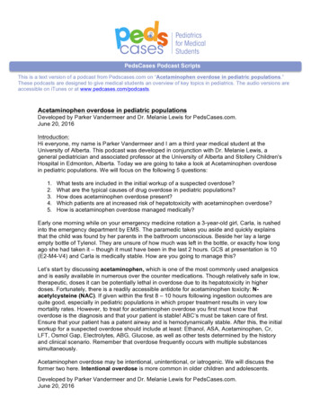
European Journal of Molecular & Clinical MedicineISSN 2515-8260Volume 07, Issue 01, 2020implant exposure to the sinus cavity, on implant survival and maxillary sinus complication,particularly with respect to the histological evidence.Because most reported results of the sinus membrane perforation are clinical observations,they lack well defined outcome criteria or control. In order to help clinicians to make propersurgical decisions, data on a more controlled scientific level is necessary to be provided .(Timmenga et al 1997)Disintegration or perforation of the sinus membrane is an unwelcome incident because ofthe need for additional surgeries. In the instance of chronic oroantral fistula occurrence, theestablished fistula enables the passage between the oral cavity and the maxillary sinus.Consequently, the microbial flora can exchange and inflammation may occur with variouspossible consequences. This simple complication might lead to major problems, be handledeasily, or recover spontaneously. Therefore, oral and maxillofacial surgeons are always carefulabout complications associated with the maxillary sinus.The aim of this study was to evaluate the effects of dental implant exposure to maxillary sinuscavity with penetrating depth of 1 mm, 2 mm, 3 mm on the osseointegration. To evaluate thenature and incidence of maxillary sinus adverse events related to endosseous implant placementwith protrusion into the maxillary sinus in a dog model after a 6-months healing period.2.Materials and Methods2.1 Implant systemIn the present study, Dentium-SuperLinefixture tapered type,endosseous dental implat(Dentium Co., Ltd, Sangpil Yoon, 150, Eondong-ro,Giheung-gu,Gyeonggi-do 443-270KOREA), made of Pure Titanium grade 4; 4 mm diameter and 10 -12 mm length is selectedto be used in this study (Fig 1).Figure (1)Dentium-SuperLine fixture4361
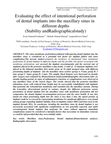
European Journal of Molecular & Clinical MedicineISSN 2515-8260Volume 07, Issue 01, 20202.2 Study sampleThe experimental animals used in the current study are sixteen healthy adult malemongrel dogs, with a weight range between 15.5-18.5 Kg and a range of age between 20-24months-old. (Sicwaten and Stahl, 1982), under observation and supervision of the veterinarianfor two weeks before the experiment to ensure acclimatization. A standard protocol of eatingregarding (quantity and quality), behavior, weight monitoring and activity was planned by theveterinarian.A split-mouth randomized design, using four treatment protocols on the positions of bilateralmaxillary first molars, was employed. At total of (32) dental implant were used in this study.Each implant recipient site was randomly assigned to one of the four treatment protocols, andimmediate implant placement was applied accordingly as follow and as illustrated in figure (2;A-D )1-) group A (n 8) was control group without sinus floor penetration;2-) group B (n 8) with penetrating depth of 1 mm;3-) group C (n 8) with penetrating depth of 2 mm;4-) group D (n 8) with penetrating depth of 3 mmGroup (A) no perforationGroup (B) 1 mm perforationGroup (C) 2 mm perforationGroup (D) 3 mm perforationFigure (2) Graphic representation of experimental groups A-D4362
European Journal of Molecular & Clinical MedicineISSN 2515-8260Volume 07, Issue 01, 20202.3 Surgical procedureThe surgical procedure including the dental extraction and implant insertion, was done in theAnimal Care Center in the College of veterinary of Duhok University.The surgical procedurewas carried out according to the standard practice, including intense disinfection for theoperating room, autoclaved surgical instruments and the use of disposable surgical kits.2.4 AnesthesiaThe experimental animal was anesthetized with an intramuscular injection of 5 ml/kg B.W. ofKetamine hydrochloride “anesthetic solution” and 0.5ml/kg B.W. of Xylazine “musclerelaxant solution; this dose of anesthetic solution kept the animal anesthetized for about 2hours.2.5 Dental extractionThe whole surgical procedure was performed under sterile conditions by only one surgeonwith a clinical experience in implant dentistry. The maxillary first molars were extractedbilaterally with special care, thin elevators were used to luxate the teeth and then extracted usingforceps with rotary movements to avoid trauma of the alveolar ridges. A plainperiapicalradiograph is taken to measure the height of residual ridge and to detect the level of thesinus floor.2.6 Dental implant insertionThe surgical insertion of the dental implants was carried out immediately after teethextraction. Thirty two sterile threaded cylindrical implants of grade 5 pure titanium wereplaced (Fig 3). Except the control group, (group A (n 8) without sinus floor penetration),eight implants were placed within the alveolar bone without protruding into the sinus cavity.The other twenty four implants were placed bilaterally in the sinus cavity in such a mannerthat they penetrated the bone and mucous membrane of the maxillary sinus floor to the extentof 1 mm (group B), 2 mm (group C) and 3 mm (group D), respectively (Fig 4).Figur(3) Implant insertion4363
European Journal of Molecular & Clinical MedicineISSN 2515-8260ACVolume 07, Issue 01, 2020BDFigure (4) Plain periapical radiographs for inserted implants in four different depths(A 0 mm; B 1mm; C 2mm; D 3mm)2.7 Primary Stability ReadingAfter the insertion of the dental implants, the first biomechanical reading (primarystability) was measured using a PeriotestMdevice (Medizintechnik Gulden – Germany).During the measurements, the Periotest M device was held horizontally with thestarting botton up. The tip of the hand piece was kept at a distance of about 2-3 mm from thedental implant abutment head. The handpiece also was perpendicular to the dental implantabutment head. Three readings for each dental implant were measured , and the mean for suchreadings was considered the final reading (Mortensen, 2007). The stability of the implantswas assessed at the time of implant placement and 6 months later.2.8 Post-operative careTo prevent postoperative infections, the animals received a post-surgical medication includeda daily penicillin intramuscular injection (2 doses of 100,000 unit /kg, penincillin G sodium )one week , and plaque control was ensured three times per week using a 0.2% chlorhexidinegel on implant placement sites with soft tooth brush. A soft diet was given to the animalsduring the healing period.4364
European Journal of Molecular & Clinical MedicineISSN 2515-8260Volume 07, Issue 01, 20202.9 Secondary stability readingAt the end of the experimental six months healing period, the animals were sacrificed byadministration of an over does of ketamine hydrochloride (Jimboet al., 2013). The surgicalsite was reopened by a small incision and the dental implants were exposed carefully then,implant abutment were adapted to the implant fixtures, then the secondary stability readingwas measured with the same technique as that followed in the primary one (Fig 5).Figure (5)Secondary stability measurement2.10 Sacrifice and samples preparationAfter dissection of the jawbones, each implant with a preserved 5-mm thickness ofperi-implant bone was removed as one piece of sample. The membrane adjacent to theimplant was separated and removed.Figure (6) Sample block.Bone(B)andFigure (7) Separation of sinus membraneSinus membrane(M) (M) from bone (B) and sinus floor (SF)4365
European Journal of Molecular & Clinical MedicineISSN 2515-8260Volume 07, Issue 01, 2020The bone specimen with dental implant was sectioned to an approximate size of 5 mmthickness of peri-implant bone using a low-speed water-cooled diamond disc, and immersedin 10% neutralized buffered formalin for four days.2.11Radiographical examinationAfter post healing period, another radiographic examination was performed withperiapical radiograph using paralleling technique, and the X-ray beam was perpendicular tothe long axis of the implant and film. All samples were shot using the following exposureconditions: 70 Kv tube voltage 10mA tube current and 0.4-second exposing time.An analysis CBCT images were obtained by using a CBCT scanner for all theexperimental animals (FONA CBCT / Italy).The examinations were performed using FONAXPan 3D CBCT cone beam computedtomography (Imaging Sciences International,Italy). The images were obtained after standardpositioning of the subjects according to the manufacturer's recommendations. Image analysiswas performed on the software, on a multiplanar reconstruction window in which the axial,coronal, and sagittal planes could be visualized in 0.5 mm intervals. CBCT datasets ofexperimental animals were selected to include and show a complete maxillary sinus, includingthe osteomeatal complex and entire maxillary floor.In the present study the images were taken for the purpose of searching for abnormalitiesin jaw bones, for examination and assessment the peri-implant status , healing process and thesurrounding bone quality and quantity, as well as evaluation of the maxillary sinus status andhealth, and assessment sinus ventilation, sinus septa, the sinus totally compartmentalized, thehypoplastic sinus, sinus aplasia, the prolapsed sinus, , mucosa thickening, sinus opacity,and otherpathologic findings in sinus such as polyps and cysts.2.12 Statistical AnalysisIn the present study, Data were analyzed using statistical package for the social sciences (SPSS)version 22.0. The penetration means differences in the cases of Bone Implant Contact percentageBIC %, Bone Area percentage BA%, Cortical Bone Thickness CBT, Membrane Thickness MT,Primary stability and Secondary stability were analyzed using Analysis of variance (ANOVA).The comparison between Primary stability and Secondary stability in different depths wereanalyzed Paired Samples T-test.3.ResultsThe results of the clinical and radiographical examinations for the operated experimentalanimals were collected throughout and after 6 months of healing and of follow up periods. Atthe time of surgical procedure, the animals showed no clinical signs of any sinus disorder. Thepostoperative healing was uneventful in all of the cases. All animals recovered rapidly fromsurgeries and were healthy throughout the follow-up period.There was not any sign of wound infection or other complications such as implant loosening orfalling except four cover screws were exposed two in the control group, one in group B and onein group C.4366
European Journal of Molecular & Clinical MedicineISSN 2515-8260Volume 07, Issue 01, 2020All the dental implants (32) were stable andhad a high percussion sound and showed nosigns of loosening during the 6 months post-operative follow-up period as verified by clinical,radio graphical examinations and biomechanical analysis (periotest reading values). The softtissue surrounding the implants looked healthy without signs of inflammation.3.1. Clinical results:3.1.1 Gross Examination ResultsThe bone at osteotomy site and membrane of sinus floor remained intact healthy withoutsings of inflammation in the control group (A) (Figure 8). In group (B) and group (C), theprotruding parts of implants that had been introduced into the sinus cavity for 1mm and 2 mmwere fully re-covered with a thin layer of newly formed membrane with a healthy appearanceand no inflammatory reaction was observed in the surrounding sinus membrane. Regeneratedbone tissue was discovered on the upper most part of some implants (Figures 9 and 10). In group(D), the parts of implants that had been penetrated into the sinus cavity for 3 mm were totallyexposed in the sinus cavity with the membrane surrounding the base of protruding parts, circularepithelium structure similar to gingival cuff formed around the base of the protruding parts anddid not show any signs of inflammation (Figure 11).Figure (8) Gross observation of the apical portion of the implant in the sinus cavity.The bonysinus floor in the control Group (A) remain intact without implant exposure (arrow). SF: sinusfloor; M: membrane; B: bone of the lateral sinus wallFigure (9) Gross observation of the apical portion of the implant in the sinus cavity.The tips withprotruding depth of 1mm Group (B) were partially covered with new bone and scars were left at4367
European Journal of Molecular & Clinical MedicineISSN 2515-8260Volume 07, Issue 01, 2020the penetrating spots on the membrane (arrow). SF: sinus floor; M: membrane; B: bone of thelateral sinus wall.Figure (10) Gross observation of the apical portion of the implant in the sinus cavity.The tipswith protruding depth of 2mm Group (C) were partially covered with new bone and scars wereleft at the penetrating spots on the membrane (arrow). SF: sinus floor; M: membrane; B: bone ofthe lateral sinus wall.Figure (11) Gross observation of the apical portion of the implant in the sinus cavity.The implanttip with protruding depth of 3mm group (D) was totally exposed in the sinus cavity with no bonycoverage and the penetrating hole was left on the sinus membrane (arrow). SF: sinus floor; M:membrane; B: bone of the lateral sinus wall.3.1.2 Biomechanical Results (Periotest Values)In all groups the values from implant stability measurements were recorded at the momentof implants placement and animal sacrifice . A high level of repeatability between differentPeriotest units had been shown as well. Successfully integrated dental implants have yielded awide range of stability readings with the Periotest.This range in values is believed to reflect bonedensity at the implant interface. No apparent differences were found among groups.4368
European Journal of Molecular & Clinical MedicineISSN 2515-8260Volume 07, Issue 01, 20203.1.2.1 Periotest Values of the Primary StabilityThe descriptive statistics including mean, standard deviation, standard error, minimum andmaximum values of the primary stability (Pr.) for all groups are shown in table (1).Table 1.Descriptive analysis oftheprimary stability for the four groups.TreatmentNo.Mean*Std. 20*The Measurements in Periotest ValueThe results of the ANOVA statistical analysis showed non-significant differences (P 0.832)between the values of Primary stability for the four groups, as shown in figures (3.7 and 3.8).0 MM1 MM2 MM3 MM-2.55-2.64-2.71-2.78Figure (12) Chart diagram for the primary stability of the four groups.3.1.2.2 Periotest Values of the Secondary StabilityThe descriptive statistics regarding mean, standard error, minimum and maximum values of thesecondary stability (Sc.) for all groups are shown in the table(2).4369
European Journal of Molecular & Clinical MedicineISSN 2515-8260Volume 07, Issue 01, 2020Table 2.Descriptive statistics of the secondary stability for the four groups.TreatmentNo.Mean*Std. Err.MinimumMaximumA8-3.230.27- 4.20-2.20B8-2.790.18- 3.40-1.80C8-2.890.24- 4.20-2.20D8-3.160.20- 3.80-2.20*The Measurements in Periotest ValueThe results of the ANOVA statistical analysis showed non-significant differences (P 0.463)between the values of secondary stability for the four groups, as shown in figures (3.9 and 3.10).0 MM1 MM-2.792 MM3 MM-2.89-3.16-3.23Figure (13) Chart diagram for the secondary stability of the four groups.3.1.2.3 Comparison between Primary and Secondary StabilityIn the current study, the Paired Samples t-test results showed non-significant differences (Pvalue) in the Periotest values between the Primary stability and the Secondary stabilitymeasures of all the groups, as shown in table (3),and figures(14 and 15).4370
European Journal of Molecular & Clinical MedicineISSN 2515-8260Volume 07, Issue 01, 2020Table 3.Comparson between Primary and Secondary stability (P-values)Group AGroup BGroup CGroupDepth0 mm1 mm2 mm3 mmP-value0.0780.3820.3680.1043 mm -2.783 mm -3.162 mm -2.712 -2.89mm-2.551 mm1-2.79mm0 mm -2.640 mm -3.23Figure (14) Chart diagram for the primary Figure (15) Chart diagram for thestability of the four groupssecondary stability of the four groups.3.2 Radiographic examination results3.2.1 Intraoral radiographRadiographic examination of the sites of implantation demonstrated a close contact ofbone and implant without radiolucent areas. The tips of implants in the control group (Group A)were completely embedded in the alveolar bone and no signs of inflammation had been seen atpri-implant area (Figures 16).The tips of implants with the penetrating depth of 1 mm (Group B) and 2 mm (Group C) weresurrounded by bone tissue with close contact near the tips of some of implants without anysignificant sigs of inflammatory reaction. (Figures 17 – 18).While the tips of implant with thepenetrating depth of3 mm (Group D) were found to protrude inside the sinus cavity without bone coverage withoutradiolucent areas around the implant (Figures 19 ).4371
European Journal of Molecular & Clinical MedicineISSN 2515-8260Volume 07, Issue 01, 2020Figure (16) Radio graphic examination pictures of the sites of implantation .The tips of implantsin the control group (A 0 mm) were completely embedded in the alveolar bone. Arrows indicatethe bony sinus floor.Figure (17) Radio graphic examination pictures of the sites of implantation . The tips of implantswith penetrating depth of (B 1 mm) were surrounded by bone tissue . Arrows indicate the bonysinus floor.Figure (18). Radio graphic examination pictures of the sites of implantation . The tips ofimplants with penetrating depth of ( C 2 mm ) . Arrows indicate the bony sinus floor.4372
European Journal of Molecular & Clinical MedicineISSN 2515-8260Volume 07, Issue 01, 2020Figure (19). Radio graphic examination pictures of the sites of implantation. The tip of implantwith the penetrating depth of ( D 3 mm) was found to protrude inside the sinus cavity with nobone coverage . Arrows indicate the bony sinus floor.3.2.2 CBCT resultsA CBCT for all the experimental animals were taken (FONA CBCT / Italy), for examinationand assessment the peri-implant status , healing process and the surrounding bone quality andquantity, as well as evaluation of the maxillary sinus status and health,including, mucosa thickening, sinus opacity, and other pathologic findings in the sinus such aspolyps and cysts etc.A DICOM viewing software program was used to analyze the images. The images werereconstructed with a slice thickness of 0.5 mm and a slice interval of 1.5 mm.The CBCT imageswere evaluated by a certified oral and maxillofacial radiologist. There was a calibration sessionprior to initiation of image evaluation to understand the purpose of the study and a trainingsession was conducted to understand the various functions of the reconstruction software.Figure (20).Panoremic view of CBCT shows implant with 0 mm perforation at right side and1mm perforation at left side of the maxillary sinus. Arrows indicate the bony sinus floor.MS: Maxillary sinus4373
European Journal of Molecular & Clinical MedicineISSN 2515-8260Volume 07, Issue 01, 2020Figure (21).Panoremic view of CBCT shows implant with 1 mm perforation at right side and 0mm perforation at left side of the maxillary sinus. Arrows indicate the bony sinus floor. MS:Maxillary sinusFigure (22).Panoremic view of CBCT shows implant with 2 mm perforation at right side and1mm perforation at left side of the maxillary sinus. Arrows indicate the bony sinus floor. MS:Maxillary sinus4374
European Journal of Molecular & Clinical MedicineISSN 2515-8260Volume 07, Issue 01, 2020Figure (23).Panoremic view of CBCT shows implant with 3 mm perforation at right side and1mm perforation at left side of the maxillary sinus. Arrows indicate the bony sinus floor. MS:Maxillary sinusFigure (24) a) Cross view of CBCT shows0 mm perforation into the maxillary sinusb) Cross view of CBCT shows1 mm perforation into the maxillary sinus4375
European Journal of Molecular & Clinical MedicineISSN 2515-8260c) Cross view of CBCT shows 2 mmperforation into the maxillary sinus4.Volume 07, Issue 01, 2020d) Cross view of CBCT shows 3 mm perforationinto the maxillary sinusDISCUSSIONThe present animal experiment was designed to evaluate whether there are differencebetween minor and major penetration of implant into maxillary sinus, with respect to their effecton implant osseointegration and maxillary sinus complication.4.1 Clinical resultsIn this experimental study, there was not any sign of wound infection or other complicationssuch as implant loosening or failure and no any adverse inflammatory reaction in the sinus, andhigh success rates were achieved. Similar findings were reported by other investigators (AbiNajm et al 2013),,(Nooh et al 2013). Different perforation sizes and depths didn't affect thesinus health, implant osseointegration and success rates.In the current study all the dental implants (32) were stable and had a high percussionsound and showed no signs of loosening during the 6 months post-operative follow-up period asverified by clinical, radio graphical examinations and biomechanical analysis (periotest readingvalues). The soft tissue surrounding the implants looked healthy without signs of l and panoramic radiographs are useful in searching fordental pathology. These radiographs are generally not helpful in documenting the presence ofsinus inflammation, and they are less specific and sensitive than computerized tomography (CT)scanning for analyzing the degree of sinus abnormalities (Brook 2009),(Longhini et al 2012). Asa result, their use has declined and they have been replaced by CT scanningIn this current study, clinical examination of the sinuses at the time of implant control nosigns of pathology. Plain films for implant control purposes seemed sufficient in addition toCBCT analysis for the sinus health .Despite the different penetrating depths, the osseointegration4376
European Journal of Molecular & Clinical MedicineISSN 2515-8260Volume 07, Issue 01, 2020in the interface between implant and bony sinus floor was observed in the surrounding sinusmembrane, suggesting that the exposed implants do not make the maxillary sinus membranevulnerable to complication. The present study revealed that disruptive membrane around theapical portion of implant healed again and re-covered the tips of implants provide the protrudingdepths were less than 2 mm. regenerated bone tissue was discovered on the uppermost part ofsome implants which indicated the self-regenerating and new bone-inducing abilities of sinusmembrane. Based on the present result, it seems that under the circumstance of everydaypractice, it is relatively safe to control the implant protrusion depth to the extent of less than 2mm in case a healthy maxillary sinus was accidentally perforated. Whereas, when the protrudingdepth was deeper than 3 mm, membrane coverage of the exposed potion could not be achieved.Circular epithelium structure similar to gingival cuff formed around the base of the protrudingparts and did not show any sign of inflammation. This observation may be explained by thedirect attachment of the membrane to the implants, forming a barrier to the sinus cavity. As forthe parts that were not covered with the sinus membrane, debris might accumulate on the surfaceof the exposed apical over time and become a potential predisposition to sinusitis.4.2 Radiological resultsIn the current study, a standardized intraoral periapical radiograph was taken on the day ofimplant placement (baseline) and after 6 months postoperatively to evaluate the bone formationaround the implant apex.Radiographic examination of the sites of implantation demonstrated aclose contact of bone and implant without radiolucent areas. The tips of impl
refined, in which dental implant are inserted marginally to the bony sinus floor with a localized augmentation procedure ( Tatum et al 1986). Sinus left and maxillary sinus augmentation are the procedures that aim to increase the vertical bone height of the alveolar bone to allow placement of dental implants for more than 30