Transcription
In-band Network Telemetry (INT) Dataplane SpecificationVersion 2.1The P4.org Applications Working Group. Contributions fromAlibaba, Arista, CableLabs, Cisco Systems, Dell, Intel, Marvell, Netronome, VMware2020-11-111
Contents1. Introduction2. Terminology3. INT Modes of Operation3.1. INT Application Modes . . . . . . . . . . . . . . . . . . . . . . . . . . . . . .3.2. INT Applied to Synthetic Traffic . . . . . . . . . . . . . . . . . . . . . . . .4. What To Monitor4.1. Device-level Information . . . . . . . . . . . . . . . . . . . . . . . . . . . . .4.2. Ingress Information . . . . . . . . . . . . . . . . . . . . . . . . . . . . . . . .4.3. Egress Information . . . . . . . . . . . . . . . . . . . . . . . . . . . . . . . .5. INT Headers5.1. INT Header Types . . . . . . . . . . . . . . . . . . . . . . . . . . . . . . . .5.2. Per-Hop Header Operations . . . . . . . . . . . . . . . . . . . . . . . . . . .5.2.1. INT Source Node . . . . . . . . . . . . . . . . . . . . . . . . . . . . . .5.2.2. INT Transit Hop Node . . . . . . . . . . . . . . . . . . . . . . . . . . .5.2.3. INT Sink Node . . . . . . . . . . . . . . . . . . . . . . . . . . . . . . .5.3. MTU Settings . . . . . . . . . . . . . . . . . . . . . . . . . . . . . . . . . . .5.4. Congestion Considerations . . . . . . . . . . . . . . . . . . . . . . . . . . . .5.5. INT over any encapsulation . . . . . . . . . . . . . . . . . . . . . . . . . . .5.6. Checksum Update . . . . . . . . . . . . . . . . . . . . . . . . . . . . . . . . .5.7. Header Location . . . . . . . . . . . . . . . . . . . . . . . . . . . . . . . . . .5.7.1. INT over IPv4/GRE . . . . . . . . . . . . . . . . . . . . . . . . . . . .5.7.2. INT over TCP/UDP . . . . . . . . . . . . . . . . . . . . . . . . . . . .5.7.3. INT over VXLAN GPE . . . . . . . . . . . . . . . . . . . . . . . . . . .5.7.4. INT over Geneve . . . . . . . . . . . . . . . . . . . . . . . . . . . . . .5.8. INT-MD Metadata Header Format . . . . . . . . . . . . . . . . . . . . . . .5.9. INT-MX Header Format . . . . . . . . . . . . . . . . . . . . . . . . . . . . .6. Examples6.1. Example with INT-MD over TCP . . . . . . . . . . . . . . . . . . . . . . . .6.2. Example with INT-MX over TCP . . . . . . . . . . . . . . . . . . . . . . . .6.3. Example with new UDP header and INT-MD inserted before TCP . . . . .6.4. Example with new UDP header and INT-MX inserted before TCP . . . . .6.5. Example with INT-MD in-between UDP header and UDP payload . . . . .6.6. Example with INT-MX in-between UDP header and UDP payload . . . . .6.7. Example with new IP and UDP headers and INT-MX inserted before IPSec6.8. Example with INT-MD over IPv4/GRE (Original packet IPv4) . . . . . . .6.9. Example with INT-MX over IPv4/GRE (Original packet IPv4) . . . . . . .6.10. Example with INT-MD over IPv4/GRE (Original packet CE or IP) . . . .6.11. Example with INT-MX over IPv4/GRE (Original packet CE or IP) . . . .6.12. Example with INT-MD over VXLAN GPE . . . . . . . . . . . . . . . . . .6.13. Example with INT-MX over VXLAN GPE . . . . . . . . . . . . . . . . . .6.14. Example with INT-MD over Geneve . . . . . . . . . . . . . . . . . . . . . .6.15. Example with INT-MX over Geneve . . . . . . . . . . . . . . . . . . . . . .6.16. Example with INT-MX including domain specific source-inserted metadata6.17. Example with INT-MD including domain specific source-only metadata . .2020-11-11 20:14In-band Network Telemetry. . . . . . . . . . . . . . . . . . . . 353637394041434445464748492
1. INTRODUCTIONA. Appendix: An extensiveA.1. Node-level . . . . . . .A.2. Ingress . . . . . . . . .A.3. Egress . . . . . . . . .A.4. Buffer Information . .A.5. Miscellaneous . . . . .B. AcknowledgementsC. Change log(but not. . . . . . . . . . . . . . . . . . . . . . . . . .exhaustive). . . . . . . . . . . . . . . . . . . . . . . . . . . . . . . . . . . .set of. . . . . . . . . . . . . . . .Metadata. . . . . . . . . . . . . . . . . . . . . . . . . . . . . . .50505051515252531. IntroductionInband Network Telemetry (“INT”) is a framework designed to allow the collection and reportingof network state, by the data plane, without requiring intervention or work by the control plane incollecting and delivering the state from the data plane. In the INT architectural model, packetsmay contain header fields that are interpreted as “telemetry instructions” by network devices. INTtraffic sources (applications, end-host networking stacks, hypervisors, NICs, send-side ToRs, etc.)can embed the instructions either in normal data packets, cloned copies of the data packets or inspecial probe packets. Alternatively, the instructions may be programmed in the network dataplane to match on particular network flows and to execute the instructions on the matched flows.These instructions tell an INT-capable device what state to collect. The network state information may be directly exported by the data plane to the telemetry monitoring system, or canbe written into the packet as it traverses the network. When the information is embedded in thepackets, INT traffic sinks retrieve (and optionally report) the collected results of these instructions,allowing the traffic sinks to monitor the exact data plane state that the packets “observed” whilebeing forwarded.Some examples of traffic sink behavior are described below: OAM – the traffic sink1 might simply collect the encoded network state, then export thatstate to an external controller. This export could be in a raw format, or could be combinedwith basic processing (such as compression, deduplication, truncation). Real-time control or feedback loops – traffic sinks might use the encoded data plane information to feed back control information to traffic sources, which could in turn use thisinformation to make changes to traffic engineering or packet forwarding. (Explicit congestionnotification schemes are an example of these types of feedback loops). Network Event Detection - If the collected path state indicates a condition that requiresimmediate attention or resolution (such as severe congestion or violation of certain data-planeinvariances), the traffic sinks1 could generate immediate actions to respond to the networkevents, forming a feedback control loop either in a centralized or a fully decentralized fashion(a la TCP).1While this will be commonly done by Sink nodes, Transit nodes may also generate OAM’s or carry out NetworkEvent Detection1While this will be commonly done by Sink nodes, Transit nodes may also generate OAM’s or carry out NetworkEvent Detection2020-11-11 20:14In-band Network Telemetry3
2. TERMINOLOGYThe INT architectural model is intended to be generic and enables a number of interesting highlevel applications, such as: Network troubleshooting and performance monitoring– Traceroute, micro-burst detection, packet history (a.k.a. postcards2 ) Advanced congestion control Advanced routing– Utilization-aware routing (For example, HULA3 , CLOVE4 ) Network data plane verificationA number of use case descriptions and evaluations are described in the Millions of Little Minionspaper 5 .2. TerminologyMonitoring System:A system that collects telemetry data sent from different network devices. The monitoringsystem components may be physically distributed but logically centralized.INT Header:A packet header that carries INT information. There are three types of INT Headers – eMbeddata (MD-type), eMbed instruction (MX-type) and Destination-type (See Section 5.1).INT Packet:A packet containing an INT Header.INT Node:An INT-capable network device that participates in the INT data plane by regularly carryingout at least one of the following: inserting, adding to, removing, or processing instructions fromINT Headers in INT packets. Depending on deployment scenarios, examples of INT Nodes mayinclude devices such as routers, switches, and NICs.INT Instruction:Instructions indicating which INT Metadata (defined below) to collect at each INT node. Theinstructions are either configured at each INT-capable node’s Flow Watchlist or written intothe INT Header.Flow Watchlist:A dataplane table that matches on packet headers and inserts or applies INT instructions oneach matched flow. A flow is a set of packets having the same values on the selected headerfields.INT Source:A trusted entity that creates and inserts INT Headers into the packets it sends. A Flow Watchlistis configured to select the flows in which INT headers are to be inserted.2I Know What Your Packet Did Last Hop: Using Packet Histories to Troubleshoot Networks, USENIX NSDI2014.3HULA: Scalable Load Balancing Using Programmable Data Planes, ACM SOSR 20164CLOVE: Congestion-Aware Load Balancing at the Virtual Edge, ACM CoNEXT 20175Millions of Little Minions: Using Packets for Low Latency Network Programming and Visibility, ACM SIGCOMM2014.2020-11-11 20:14In-band Network Telemetry4
3. INT MODES OF OPERATIONINT Sink:A trusted entity that extracts the INT Headers and collects the path state contained in the INTHeaders. The INT Sink is responsible for removing INT Headers so as to make INT transparentto upper layers. (Note that this does not preclude having nested or hierarchical INT domains.)The INT Sink can decide to send the collected information to the monitoring system.INT Transit Hop:A trusted entity that collects metadata from the data plane by following the INT Instructions.Based on the instructions, the data may be directly exported to the telemetry monitoring systemor embedded into the INT Header of the packet.Note that one physical device may play multiple roles – INT Source, Transit, Sink – at the sametime for the same or different flows. For example, an INT Source node may embed its own metadatainto the packet, playing the roles of INT Transit as well.INT Metadata:Information that an INT Source or an INT Transit Hop node inserts into the INT Header, orinto a telemetry report. Examples of metadata are described in Section 4.INT Domain:A set of inter-connected INT nodes under the same administration. This specification definesthe behavior and packet header formats for interoperability between INT nodes from differentvendors in an INT domain. The INT nodes within the same domain must be configured ina consistent way to ensure interoperability between the nodes. Operators of an INT domainshould deploy INT Sink capability at domain edges to prevent INT information from leakingout of the domain.3. INT Modes of OperationSince INT was first introduced at P4.org in 2015, a number of variations of INT have been evolvedand discussed in IETF and industry communities. Also the term ‘INT’ has been used to broadlyindicate data plane telemetry in general, not limited to the original classic INT where both instructions and metadata are embedded in the data packets. Hence we define different modes of INToperation based on the degree of packet modifications, i.e., what to embed in the packets.The different modes of operation are described in detail below, and summarized in Figure 1.3.1. INT Application ModesOriginal data packets are monitored and may be modified to carry INT instructions and metadata.There are three variations based on the level of packet modifications. INT-XD (eXport Data): INT nodes directly export metadata from their dataplane to themonitoring system based on the INT instructions configured at their Flow Watchlists. Nopacket Modification is needed.This mode was also known as “Postcard” mode in the previous versions of the TelemetryReport spec, originally inspired by 2 .2I Know What Your Packet Did Last Hop: Using Packet Histories to Troubleshoot Networks, USENIX NSDI2014.2020-11-11 20:14In-band Network Telemetry5
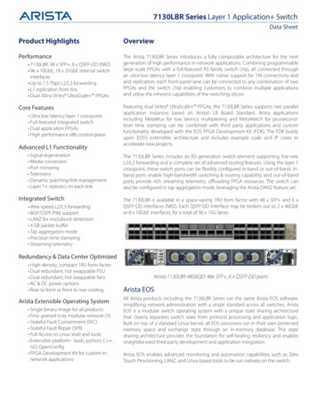
3.2. INT Applied to Synthetic Traffic3. INT MODES OF OPERATIONINTIn-band Network TelemetryEXport DataEMbed Instruct(X)ionsEMbed DataEach node exports metadatabased on Watchlist config.(aka postcards)Embed only Instructions in the pkt.Each node exports metadata.(aka IOAM Immediate Export)Embed instructions and metadata,export at the sink node.INT-XDINT-MXINT-MDNo packet modificationsLimited packet modifications(Instructions only)Packet modifications(Instructions & Metadata)(classic INT)Figure 1. Various modes of INT operation. INT-MX (eMbed instruct(X)ions): The INT Source node embeds INT instructions in thepacket header, then the INT Source, each INT Transit, and the INT sink directly send themetadata to the monitoring system by following the instructions embedded in the packets.The INT Sink node strips the instruction header before forwarding the packet to the receiver.Packet modification is limited to the instruction header, the packet size doesn’t grow as thepacket traverses more Transit nodes.INT-MX also supports ‘source-inserted’ metadata as part of Domain Specific Instructions.This allows the INT Source to embed additional metadata that other nodes or the monitoringsystem can consume.This mode is inspired by IOAM’s “Direct Export”6 7. INT-MD (eMbed Data): In this mode both INT instructions and metadata are written intothe packets. This is the classic hop-by-hop INT where 1) INT Source embeds instructions,2) INT Source & Transit embed metadata, and 3) INT Sink strips the instructions andaggregated metadata out of the packet and (selectively) sends the data to the monitoringsystem. The packet is modified the most in this mode while it minimizes the overhead at themonitoring system to collate reports from multiple INT nodes.Since v2.0, INT-MD mode supports ‘source-only’ metadata as part of Domain Specific Instructions. This allows the INT Source to embed additional metadata for the INT Sink orthe monitoring system to consume.NOTE: the rest of the spec is assuming INT-MD as the default mode, unless specifiedotherwise.3.2. INT Applied to Synthetic TrafficINT Source nodes may generate INT-marked synthetic traffic either by cloning original data packetsor by generating special probe packets. INT is applied to this traffic by transit nodes in exactly67Data Fields for In-situ OAM, draft-ietf-ippm-ioam-data-09, March 2020.In-situ OAM Direct Exporting, draft-ietf-ippm-ioam-direct-export-00, February 2020.2020-11-11 20:14In-band Network Telemetry6
4. WHAT TO MONITORthe same way as all traffic.The only difference between live traffic and Synthetic traffic is that INT Sink nodes may needto discard synthetic traffic after extracting the collected INT data as opposed to forwarding thetraffic. This is indicated by using the ‘D’ bit of the INT Header to mark relevant packets as beingcopies/clones or probes, to be ’D’iscarded at the INT Sink.All INT modes may be used on these synthetic/probe packets, as decided by the INT Sourcenode. Specifically the INT-MD (eMbed Data) mode applied to Synthetic or probe packets allowsfunctionality similar to IFA8 .It is likely that synthetic traffic created by cloning would be discarded at the Sink, whileProbe packets might be marked for forwarding or discarding, depending on the use-case. It is theresponsibility of the INT Source node to mark packets correctly to determine if the INT Sink willforward or discard packets after extracting the INT Data collected along the path.4. What To MonitorIn theory, one may be able to define and collect any device-internal information using the INTapproach. In practice, however, it seems useful to define a small baseline set of metadata that canbe made available on a wide variety of devices: the metadata listed in this section comprises sucha set. As the INT specification evolves, we expect to add more metadata to this INT specification.The exact meaning of the following metadata (e.g., the unit of timestamp values, the precisedefinition of hop latency, queue occupancy or buffer occupancy) can vary from one device to anotherfor any number of reasons, including the heterogeneity of device architecture, feature sets, resourcelimits, etc. Thus, defining the exact meaning of each metadata is beyond the scope of this document.Instead we assume that the semantics of metadata for each device model used in a deployment iscommunicated with the entities interpreting/analyzing the reported data in an out-of-band fashion.4.1. Device-level InformationNode idThe unique ID of an INT node. This is generally administratively assigned. Node IDs must beunique within an INT domain.4.2. Ingress InformationIngress interface identifierThe interface on which the INT packet was received. A packet may be received on an arbitrarystack of interface constructs starting with a physical port. For example, a packet may be receivedon a physical port that belongs to a link aggregation port group, which in turn is part of a Layer3 Switched Virtual Interface, and at Layer 3 the packet may be received in a tunnel. Althoughthe entire interface stack may be monitored in theory, this specification allows for monitoringof up to two levels of ingress interface identifiers. The first level of ingress interface identifierwould typically be used to monitor the physical port on which the packet was received, hence a16-bit field (half of a 4-Byte metadata) is deemed adequate. The second level of ingress interfaceidentifier occupies a full 4-Byte metadata field, which may be used to monitor a logical interface8Inband Flow Analyzer, draft-kumar-ippm-ifa-02, April 2020.2020-11-11 20:14In-band Network Telemetry7
4.3. Egress Information4. WHAT TO MONITORon which the packet was received. A 32-bit space at the second level allows for an adequatelylarge number of logical interfaces at each network element. The semantics of interface identifiersmay differ across devices, each INT hop chooses the interface type it reports at each of the twolevels.Ingress timestampThe device local time when the INT packet was received on the ingress physical or logical port.4.3. Egress InformationEgress interface identifierThe interface on which the INT packet was sent out. A packet may be transmitted on anarbitrary stack of interface constructs ending at a physical port. For example, a packet may betransmitted on a tunnel, out of a Layer 3 Switched Virtual Interface, on a Link AggregationGroup, out of a particular physical port belonging to the Link Aggregation Group. Althoughthe entire interface stack may be monitored in theory, this specification allows for monitoring ofup to two levels of egress interface identifiers. The first level of egress interface identifier wouldtypically be used to monitor the physical port on which the packet was transmitted, hence a16-bit field (half of a 4-Byte metadata) is deemed adequate. The second level of egress interfaceidentifier occupies a full 4-Byte metadata field, which may be used to monitor a logical interfaceon which the packet was transmitted. A 32-bit space at the second level allows for an adequatelylarge number of logical interfaces at each network element. The semantics of interface identifiersmay differ across devices, each INT hop chooses the interface type it reports at each of the twolevels.Egress timestampThe device local time when the INT packet was processed by the egress physical or logical port.Hop latencyTime taken for the INT packet to be switched within the device.Egress interface TX Link utilizationCurrent utilization of the egress interface via which the INT packet was sent out. Again, devicescan use different mechanisms to keep track of the current rate, such as bin bucketing or movingaverage. While the latter is clearly superior to the former, the INT framework does not stipulatethe mechanics and simply leaves those decisions to device vendors.Queue occupancyThe build-up of traffic in the queue (in bytes, cells, or packets) that the INT packet observes inthe device while being forwarded. The format of this 4-octet metadata field is implementationspecific and the metadata semantics YANG model shall describe the format and units of thismetadata field in the metadata stack.Buffer occupancyThe build-up of traffic in the buffer (in bytes, cells, or packets) that the INT packet observes inthe device while being forwarded. Use case is when the buffer is shared between multiple queues.The format of this 4-octet metadata field is implementation specific and the metadata semanticsYANG model shall describe the format and units of this metadata field in the metadata stack.A metadata semantics YANG model 9 is being developed that allows nodes to report details of themetadata format, units, and semantics.9p4-dtel-metadata-semantics, s.yang2020-11-11 20:14In-band Network Telemetry8
5. INT HEADERS5. INT HeadersThis section specifies the format and location of INT Headers. INT Headers and their locationsare relevant for INT-MX and INT-MD modes where the INT instructions (and metadata stack incase of MD mode) are written into the packets.5.1. INT Header TypesThere are three types of INT Headers: MD-type, MX-type and Destination-type. A given INTpacket may carry either of MD or MX type headers, and/or a Destination-type header. WhenDestination-type and MD-type or MX-type headers are present, the MD-type header or MX-typeheader must precede the Destination-type header. MD-type (INT Header type 1)– Intermediate nodes (INT Transit Hops) must process this type of INT Header. Theformat of this header is defined in Section 5.8. Destination-type (INT Header type 2)– Destination headers must only be consumed by the INT Sink. Intermediate nodes mustignore Destination headers.– Destination headers can be used to enable Edge-to-Edge communication between theINT Source and INT Sink. For example:* INT Source can add a sequence number to detect loss of INT packets.* INT Source can add the original values of IP TTL and INT Remaining Hop Count,thus enabling the INT sink to detect network devices on the path that do notsupport INT by comparing the IP TTL decrement against INT Remaining HopCount decrement (assuming each network device is an L3 hop)– The format of Destination-type headers will be defined in a future revision. Note someEdge-to-Edge INT use cases can be supported by ‘source-only’ and ‘source-inserted’metadata, part of Domain Specific Instructions in the MD-type and MX-type headers. MX-type (INT Header type 3)– Intermediate nodes (INT Transit Hops) must process this type of INT Header and generate reports to the monitoring system as instructed. The format of this header is definedin Section 5.9.5.2. Per-Hop Header Operations5.2.1. INT Source NodeIn the INT-MD and INT-MX modes, the INT Source node in the packet forwarding path createsthe INT-MD or INT-MX Header.In INT-MD, the source node add its own INT metadata after the header. To avoid exhaustingheader space in the case of a forwarding loop or any other anomalies, it is strongly recommended tolimit the number of total INT metadata fields added by Transit Hop nodes by setting the RemainingHop Count field in INT header appropriately.The INT-MD and INT-MX headers are described in detail in the subsequent sections.2020-11-11 20:14In-band Network Telemetry9
5.3. MTU Settings5. INT HEADERS5.2.2. INT Transit Hop NodeIn the INT-MD mode, each node in the packet forwarding path creates additional space in theINT-MD Header on-demand to add its own INT metadata. To avoid exhausting header space inthe case of a forwarding loop or any other anomalies, each INT Transit Hop must decrement theRemaining Hop Count field in the INT header appropriately.In the INT-MX mode, each node in the packet forwarding path follows the intructions in theINT-MX Header, gathers the device specific metadata and exports the device metadata using theTelemetry Report.INT Transit Hop nodes may update the DS Flags field in the INT-MD or INT-MX header. TheHop ML, Instruction Bitmap, Domain Specific ID and DS Instruction fields must not be modifiedby Transit Hop nodes.5.2.3. INT Sink NodeIn INT-MD mode, the INT Sink node removes the INT Headers and Metadata stack from thepacket, and decides whether to report the collected information.In INT-MX mode, the INT Sink node removes the INT-MX header, gathers the device specificmetadata and decides whether to report that metadata.5.3. MTU SettingsIn both INT-MX and INT-MD modes, it is possible that insertion of the INT header at the INTSource node may cause the egress link MTU to be exceeded.In INT-MD mode, as each hop creates additional space in the INT header to add its metadata,the packet size increases. This can potentially cause egress link MTU to be exceeded at an INTnode.This may be addressed in the following ways It is recommended that the MTU of links between INT sources and sinks be configured toa value higher than the MTU of preceding links (server/VM NIC MTUs) by an appropriateamount. Configuring an MTU differential of [Per-hop Metadata Length*4*INT Hop Count Fixed INT Header Length] bytes (just [Fixed INT Header Length] for INT-MX mode),based on conservative values of total number of INT hops and Per-hop Metadata Length,will prevent egress MTU being exceeded due to INT metadata insertion at INT hops. TheFixed INT Header Length is the sum of INT metadata header length (12B) and the size ofencapsulation-specific shim/option header (4B) as defined in Section 5.7. An INT source/transit node may optionally participate in dynamic discovery of Path MTUfor flows being monitored by INT by transmitting ICMP message to the traffic source asper Path MTU Discovery mechanisms of the corresponding L3 protocol (RFC 1191 for IPv4,RFC 1981 for IPv6). An INT source or transit node may report a conservative MTU in theICMP message, assuming that the packet will go through the maximum number of allowedINT hops (i.e. Remaining Hop Count will decrement to zero), accounting for cumulativemetadata insertion at all INT hops, and assuming that the egress MTU at all downstreamINT hops is the same as its own egress link MTU. This will help the path MTU discoverysource to converge to a path MTU estimate faster, although this would be a conservativepath MTU estimate. Alternatively, each INT hop may report an MTU only accounting for2020-11-11 20:14In-band Network Telemetry10
5.4. Congestion Considerations5. INT HEADERSthe metadata it inserts. This would enable the path MTU discovery source converge to aprecise path MTU, at the cost of receiving more ICMP messages, one from each INT hop.Regardless of whether or not an INT transit node participates in Path MTU discovery, if it cannotinsert all requested metadata because doing so will cause the packet length to exceed egress linkMTU, it must either: not insert any metadata and set the M bit in the INT header, indicating that egress MTUwas exceeded at an INT hop, or report the metadata stack collected from previous hops (setting the Intermediate Report bit ifa Telemetry Report 2.0 16 packet is generated) and remove the reported metadata stack fromthe packet, including the metadata from this transit hop in either the report or embeddingin the INT-MD metadata header.An INT source inserts 12 bytes of fixed INT headers, and may also insert Per-hop MetadataLength*4 bytes of its own metadata. If inserting the fixed headers causes egress link MTU to beexceeded, INT cannot not be initiated for such packets. If an INT source is programmed to insertits own INT metadata, and there is enough room in a packet to insert fixed INT headers, but noadditional room for its INT metadata, the source must initiate INT and set the M bit in the INTheader.In theory, an INT transit node can perform IPv4 fragmentation to overcome egress MTU limitation when inserting its metadata. However, IPv4 fragmentation can have adverse impact onapplications. Moreover, IPv6 packets cannot be fragmented at intermediate hops. Also, fragmenting packets at INT transit hops, with or without copying preceding INT metadata into fragmentsimposes extra complexity of correlating fragments in the INT monitoring engine. Considering allthese factors, this specification requires that an INT node must not fragment packets in order toappend INT information to the packet.5.4. Congestion ConsiderationsUse of the INT encapsulation should not increase the impact of congestion on the network. Whilemany transport protocols (e.g. TCP, SCTP, DCCP, QUIC) inherently provide congestion controlmechanisms, other transport protocols (e.g. UDP) do not. For the latter case, applications mayprovide congestion control or limit the traffic volume.It is recommended not to apply INT to application traffic that is known not to be congestioncontrolled (as described in RFC 8085 10 Section 3.1.11). In order to achieve this, packet filteringmechanisms such as access control lists should be provided, with match criteria including IP protocoland L4 ports.Because INT encapsulation endpoints are located within the same administrative domain, anoperator may allow for INT encapsulation of traffic that is known not to be congestion controlled.In this case, the operator should carefully consider the potential impact of congestion, and implement appropriate mechanisms for controlling or mitigating the effects of congestion. This includescapacity planning, traffic engineering, rate limiting, and other mechanisms.1610Telemetry Report Format Specification Version 2.0, May 2020.UDP Usage Guidelines, RFC 8085, March 2017.2020-11-11 20:14In-band Network Telemetry11
5.5. INT over any encapsulation5. INT HEADERS5.5. INT over any encapsulationThe specific location for INT Headers is intentionally not specified: an INT Header can be inserted as an option or payload of any encapsulation type. The only requirements are that theencapsulation header provides sufficient space to carry the INT information and that all INT nodes(Sources, transit hops and Sinks)
In-band Network Telemetry (INT) Dataplane Specification Version 2.1 The P4.org Applications Working Group. Contributions from Alibaba, Arista, CableLabs, Cisco Systems, Dell, Intel, Marvell, Netronome, VMware 2020-11-11 1. Contents 1. Introduction 3 2. Terminology 4 3. INT Modes of Operation 5


![NIAS EN COLOMBIA - Normas de Aseguramiento [Modo de compatibilidad]](/img/18/nias-en-colombia-normas-de-aseguramiento.jpg)