Transcription
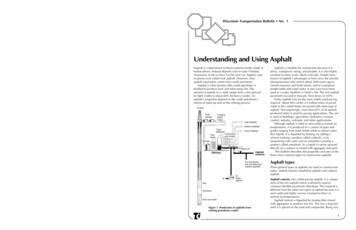
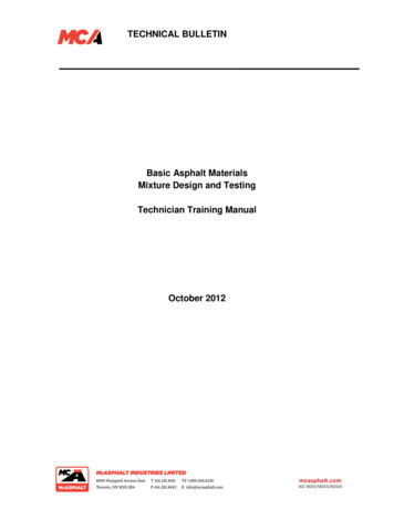
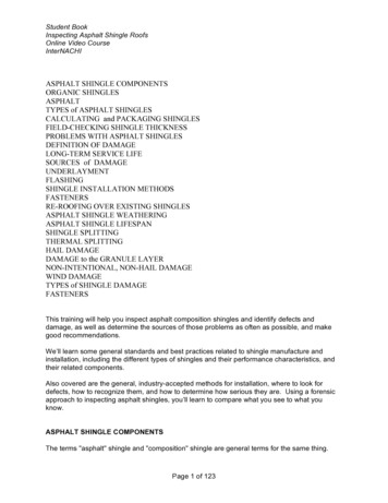
Electronic copies of the most current TSM issue can be found on the Viking Pump website at www.vikingpump.comTECHNICAL SERVICE MANUALJACKETED ASPHALT PUMPSSERIES 34 AND 434SIZES HL, KK, LQ, Q, M, NSECTIONTSM 430PAGE1 OF 9ISSUEINOTE: The Technical Service Manual for the electrically heated pumps is located in the Universal Seal manuals:TSM 630.1 (H-LL sizes), TSM 630.2 (LS-QS sizes) and TSM 630.3 (N-RS sizes)CONTENTSIntroduction . . . . . . . . . . . . . . . . . . . . . . . .1Special Information . . . . . . . . . . . . . . . . . . . .1Safety Information . . . . . . . . . . . . . . . . . . . . 2Maintenance . . . . . . . . . . . . . . . . . . . . . . .3Disassembly . . . . . . . . . . . . . . . . . . . . . . .6Assembly . . . . . . . . . . . . . . . . . . . . . . . . .7Valve Instructions . . . . . . . . . . . . . . . . . . . . .8INTRODUCTIONThe illustrations used in this manual are for identificationpurposes only and should not be used for ordering parts.Secure a parts list from the factory or a Viking representative.Always give complete name of part, part number and materialwith the model and serial number of the pump when orderingrepair parts.UNMOUNTED PUMPUNITSPACKED MECH. SEALHL34HL434KK34KK434LQ34LQ434Q34Q434R Reducer UnitM34M434P Purchased Reducer UnitN34N434V V-belt UnitUnits are designated by theunmounted pump modelnumbers followed by a letterindicating drive style.SPECIAL INFORMATIONDANGER !Before opening any Viking pump liquidchamber (pumping chamber, reservoir,relief valve adjusting cap fitting, etc.)Be sure:1. That any pressure in the chamber has beencompletely vented through the suctionor discharge lines or other appropriateopenings or connections.2. That the driving means (motor, turbine,engine, etc.) has been “locked out” ormade non-operational so that it cannot bestarted while work is being done on pump.3. That you know what liquid the pumphas been handling and the precautionsnecessary to safely handle the liquid.Obtain a material safety data sheet (MSDS)for the liquid to be sure these precautionsare understood.Failure to follow above listed precautionarymeasures may result in serious injury or death.This manual deals exclusively with series 34 and 434Jacketed General Purpose Pumps. Refer to Figures 1through 11 for general configuration and nomenclature usedin this manual.FIGURE 1ILLUSTRATION OF SERIES 34JACKETED PUMPFIGURE 2CUTAWAY VIEW OF SERIES 434JACKETED PUMPNOTE: HL, KK AND SERIES 434 SEALED PUMPS DISCONTINUED AS OF 1Q16.VIKING PUMP, INC. A Unit of IDEX Corporation Cedar Falls, IA 50613 USA
SAFETY INFORMATION AND INSTRUCTIONSIMPROPER INSTALLATION, OPERATION OR MAINTENANCE OF PUMP MAY CAUSE SERIOUS INJURYOR DEATH AND/OR RESULT IN DAMAGE TO PUMP AND/OR OTHER EQUIPMENT. VIKING’S WARRANTYDOES NOT COVER FAILURE DUE TO IMPROPER INSTALLATION, OPERATION OR MAINTENANCE.THIS INFORMATION MUST BE FULLY READ BEFORE BEGINNING INSTALLATION, OPERATION ORMAINTENANCE OF PUMP AND MUST BE KEPT WITH PUMP. PUMP MUST BE INSTALLED, OPERATEDAND MAINTAINED ONLY BY SUITABLY TRAINED AND QUALIFIED PERSONS.THE FOLLOWING SAFETY INSTRUCTIONS MUST BE FOLLOWED AND ADHERED TO AT ALL TIMES.SymbolLegend :!!Danger - Failure to follow the indicatedinstruction may result in serious injuryor death.BEFORE opening any liquid chamber (pumpingchamber, reservoir, relief valve adjusting cap fitting,etc.) be sure that : Any pressure in the chamber has been completelyvented through the suction or discharge lines orother appropriate openings or connections. The pump drive system means (motor, turbine,engine, etc.) has been “locked out” or otherwisebeen made non-operational so that it cannot bestarted while work is being done on the pump.WARNINGWARNING!WARNING You know what material the pump has beenhandling, have obtained a material safety datasheet (MSDS) for the material, and understandand follow all precautions appropriate for the safehandling of the material.!!!!WARNING!WARNINGBEFORE operating the pump, be sure all drive guardsare in place.DO NOT operate pump if the suction or dischargepiping is not connected.!!DO NOT place fingers into the pumping chamber orits connection ports or into any part of the drive trainif there is any possibility of the pump shafts beingrotated.DO NOT exceed the pumps rated pressure, speed, andtemperature, or change the system/duty parametersfrom those the pump was originally supplied, withoutconfirming its suitability for the new service.!WARNINGBEFORE operating the pump, be sure that: It is clean and free from debris all valves in the suction and discharge pipelinesare fully opened. All piping connected to the pump is fully supportedand correctly aligned with the pump. Pump rotation is correct for the desired directionof flow.!WARNINGSECTION TSM 430ISSUEIPAGE 2 OF 9Warning - In addition to possible seriousinjury or death, failure to follow theindicated instruction may cause damageto pump and/or other equipment.INSTALL pressure gauges/sensors next to thepump suction and discharge connections to monitorpressures.USE extreme caution when lifting the pump. Suitablelifting devices should be used when appropriate. Liftingeyes installed on the pump must be used only to liftthe pump, not the pump with drive and/or base plate.If the pump is mounted on a base plate, the base platemust be used for all lifting purposes. If slings are usedfor lifting, they must be safely and securely attached.For weight of the pump alone (which does not includethe drive and/or base plate) refer to the Viking Pumpproduct catalog.DO NOT attempt to dismantle a pressure relief valvethat has not had the spring pressure relieved or ismounted on a pump that is operating.AVOID contact with hot areas of the pump and/ordrive. Certain operating conditions, temperaturecontrol devices (jackets, heat-tracing, etc.), improperinstallation, improper operation, and impropermaintenance can all cause high temperatures on thepump and/or drive.THE PUMP must be provided with pressure protection.This may be provided through a relief valve mounteddirectly on the pump, an in-line pressure relief valve,a torque limiting device, or a rupture disk. If pumprotation may be reversed during operation, pressureprotection must be provided on both sides of pump.Relief valve adjusting screw caps must always pointtowards suction side of the pump. If pump rotation isreversed, position of the relief valve must be changed.Pressure relief valves cannot be used to control pumpflow or regulate discharge pressure. For additionalinformation, refer to Viking Pump’s Technical ServiceManual TSM 000 and Engineering Service BulletinESB-31.THE PUMP must be installed in a matter that allowssafe access for routine maintenance and for inspectionduring operation to check for leakage and monitorpump operation.NOTE: HL, KK AND SERIES 434 SEALED PUMPSDISCONTINUED AS OF 1Q16.
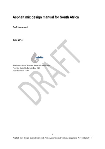
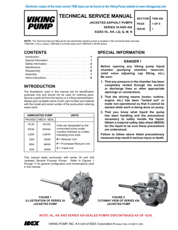
ROTATION: Viking pumps operate equally well in a clockwiseor counter clockwise rotation. Shaft rotation determineswhich port is suction and which is discharge. Port in areawhere pumping elements (gear teeth) come out of mesh issuction port.low temperatures will require other types of lubrication.Refer to Engineering Service Bulletin ESB-515. Consultfactory with specific lubrication questions.2.PACKING ADJUSTMENT: New packed pumps generallyrequire some initial packing adjustment to control leakageas packing “runs-in”. Make initial packing adjustmentscarefully and do not over-tighten the packing gland. Afterinitial adjustment occasional inspection will reveal theneed for packing gland adjustment and/or replacementof the packing. See instructions in disassembly andreassembly regarding re-packing the pump.3.END CLEARANCE ADJUSTMENT: After long termoperation it is sometimes possible to improve theperformance of the pump, without major repair, throughadjustment of end clearance of the pump. Refer toinstructions under Step 3 of Assembly, page 7.4.CLEANING PUMP: It is good practice to keep the pumpas clean as possible. This will facilitate inspection,adjustment and repair work and help prevent omissionof lubrication to fittings covered or hidden with dirt.5.STORAGE: If pump is to be stored, or not used for anyappreciable length of time it should be drained and alight coat of lubricating and preservative oil should beapplied to the internal parts. Lubricate all fittings. Besure to drain all steam jacket chambers to preventfreezing during cold weather. Tighten all assembly boltsbefore the pump is put into service after being stored.PRESSURE RELIEF VALVES:1.Viking pumps are positive placement pumps and mustbe provided with some sort of pressure protection. Thismay be a relief valve mounted directly on the pump, anin-line pressure relief valve, a torque limiting device or arupture disk.2.There are relief valve options available on these pumps.Options may include a plain or a jacketed relief valvedepending on the pump size. Pumps equipped with ajacketed head plate are generally not available with arelief valve.3.If pump rotation is to be reversed during operation,pressure protection must be provided on both sides ofpump.4.Relief valve adjusting screw cap must always pointtowards suction side of pump. If pump rotation isreversed, remove pressure relief valve and turn end forend.5.Pressure relief valves cannot be used to control pumpflow or regulate discharge pressure.For additional information on pressure relief valves, Refer toTechnical Service Manual TSM000 and Engineering ServiceBulletin ESB-31.MAINTENANCESeries 34 and 434 jacketed pumps are designed for long,trouble-free service life under a wide variety of applicationconditions with a minimum of maintenance, however, thefollowing should be considered.1.LUBRICATION: External lubrication must be appliedslowly with a handgun to all lubrication fittings every 500hours of operation with multi-purpose grease, NLGI # 2.Do not over-grease. Applications involving very high orSUGGESTED REPAIR TOOLS: The following tools must beavailable to properly repair Series 34 and 434 pumps. Thesetools are in addition to standard mechanics’ tools such asopen end wrenches, pliers, screwdrivers etc. Most of theitems can be obtained from an industrial supply house.1. Soft Headed Hammer2. Packing hooks, flexible (packed pumps)Small for up to 5/16”, G-KK (2-810-049-999)Large for 3/8” and larger, L size and up (2-810-042-999).3. Arbor Press4. Allen wrenches (for mechanical seals)5. Feeler gage set (for mechanical seals)FIGURE 3EXPLODED VIEWSERIES 34 & 434 PUMPS (HL SIZE)ITEMNAME OF PART1Mechanical Seal2345ITEMNAME OF PARTITEMPacking Retainer WasherNut9Casing Bushing16Idler PinLockwasher10Casing (Jacketed)17Head (Jacketed) and Idler Pin AssemblyFlat Washer11Pipe Plug18CapscrewStud12Rotor and Shaft AssemblyNot Illus.Relief Valve6Packing Gland13Idler and Bushing AssemblyNot Illus.Relief Valve Gasket7Packing14Idler BushingNot Illus.Relief Valve CapscrewsNOTE: HL, KK AND SERIES 434 SEALED PUMPSDISCONTINUED AS OF 1Q16.15NAME OF PART8Head Gasket SetSECTION TSM 430ISSUEIPAGE 3 OF 9
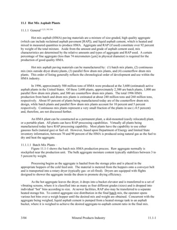
FIGURE 4EXPLODED VIEWSERIES 34 & 434 PUMPS (KK SIZE)ITEM1NAME OF PARTITEMMechanical Seal9NAME OF PARTITEMNAME OF PARTRotor Bearing Sleeve Bushing17Idler Bushing2Nut10Rotor Bearing Sleeve18Head Gasket Set3Lockwasher11Gasket19Idler Pin4Flat Washer12Pipe Plug20Head (Jacketed) and Idler Pin Assembly5Stud13Capscrew21Capscrew6Packing Gland14Casing (Jacketed)Not Illus.Relief Valve7Packing15Rotor and Shaft AssemblyNot Illus.Relief Valve Gasket8Packing Retainer Washer16Idler and Bushing AssemblyNot Illus.Relief Valve CapscrewsFIGURE 5EXPLODED VIEWSERIES 34 & 434 PUMPS (LQ SIZE)ITEMNAME OF PARTITEMNAME OF PARTITEMNAME OF PART1Mechanical Seal11Pipe Plug21Idler and Bushing Assembly2Nut12Gasket22Idler Bushing3Lockwasher13Nut23Head Gasket Set4Flat Washer14Stud24Idler Pin5Stud15Pipe Plug25Head (Jacketed) and Idler Pin Assembly6Packing Gland16Casing (Jacketed)26Capscrew7Packing17GasketNot Illus.Relief Valve8Packing Retainer Washer18NutNot Illus.Relief Valve Gasket9Rotor Bearing Sleeve Bushing19StudNot Illus.Relief Valve Capscrews10Rotor Bearing Sleeve20Rotor and Shaft AssemblySECTION TSM 430ISSUEIPAGE 4 OF 9NOTE: HL, KK AND SERIES 434 SEALED PUMPSDISCONTINUED AS OF 1Q16.
FIGURE 6EXPLODED VIEWSERIES 34 & 434 PUMPS (Q SIZE)ITEM1NAME OF PARTMechanical SealITEM11NAME OF PARTITEMNAME OF PARTPipe Plug21Rotor and Shaft Assembly2Nut12Gasket22Idler and Bushing Assembly3Lockwasher13Thrust Washer, Rotor Bearing Sleeve23Idler Bushing4Flat Washer14Thrust Washer, Rotor24Head Gasket Set5Stud15Nut25Idler Pin6Packing Gland16Stud26Head (Jacketed) and Idler Pin Assembly7Packing17Pipe PlugNot Illus.Relief Valve8Packing Retainer Washer18Casing (Jacketed)Not Illus.Relief Valve Gasket9Rotor Bearing Sleeve Bushing19Pipe PlugNot Illus.Relief Valve Capscrews10Rotor Bearing Sleeve20GasketFIGURE 7EXPLODED VIEWSERIES 34 & 434 PUMPS (M SIZE)ITEM1NAME OF PARTMechanical SealITEM11NAME OF PARTITEMNAME OF PARTPipe Plug21Head Gasket Set2Nut12Gasket22Rotor and Shaft Assembly3Lockwasher13Thrust Washer, Rotor Bearing Sleeve23Idler Bushing4Flat Washer14Thrust Washer, Rotor24Idler and Bushing Assembly5Stud15Nut25Head Gasket Set6Packing Gland16Stud26Idler Pin7Packing17Pipe Plug27Head (Jacketed) and Idler Pin Assembly8Packing Retainer Washer18Casing (Jacketed)Not Illus.Relief Valve9Rotor Bearing Sleeve Bushing19Pipe PlugNot Illus.Relief Valve Gasket10Rotor Bearing Sleeve20GasketNot Illus.Relief Valve CapscrewsNOTE: HL, KK AND SERIES 434 SEALED PUMPSDISCONTINUED AS OF 1Q16.SECTION TSM 430ISSUEIPAGE 5 OF 9
FIGURE 8EXPLODED VIEWSERIES 34 & 434 PUMPS (N SIZE)ITEMNAME OF PARTITEMNAME OF PARTITEMNAME OF PART1Mechanical Seal12Gasket23Rotor and Shaft Assembly2Nut13Thrust Washer, Rotor Bearing Sleeve24Idler and Bushing Assembly3Lockwasher14Thrust Washer, Rotor25Idler Bushing4Flat Washer15Nut26Head Gasket Set5Stud16Stud27Idler Pin6Packing Gland17Pipe Plug28Head (Jacketed) and Idler Pin Assembly7Packing18Casing (Jacketed)Not Illus.Relief Valve8Packing Retainer Washer19Pipe PlugNot Illus.Relief Valve Gasket9Rotor Bearing Sleeve Bushing20GasketNot Illus.Relief Valve Capscrews10Rotor Bearing Sleeve21Nut11Pipe Plug22StudDISASSEMBLYDANGER !Before opening any Viking pump liquidchamber (pumping chamber, reservoir,relief valve adjusting cap fitting, etc.)Be sure:1.Allow pump to cool. Remove the head from the pump.If pump is furnished with a relief valve it need not beremoved from head or disassembled at this point.2.For mechanical seal pumps, remove any flush linesgoing to the mechanical seal if this has not already beendone.1. That any pressure in the chamber has beencompletely vented through the suctionor discharge lines or other appropriateopenings or connections.2. That the driving means (motor, turbine,engine, etc.) has been “locked out” ormade non-operational so that it cannot bestarted while work is being done on pump.3. That you know what liquid the pumphas been handling and the precautionsnecessary to safely handle the liquid.Obtain a material safety data sheet (MSDS)for the liquid to be sure these precautionsare understood.Failure to follow above listed precautionarymeasures may result in serious injury or death.NOTE: Mark the head and casing before disassembly toinsure proper reassembly. The idler pin, which is offset inpump head, should be properly positioned toward and equaldistance between the port connections to allow for properflow of liquid through the pump.SECTION TSM 430ISSUEIPAGE 6 OF 9CAUTION !Do not allow the idler to fall from the idlerpin. Tilting the head up as it is removed willprevent this occurrence. Avoid damagingthe head gasket if possible.3.For pumps with X-100 or X-200 mechanical seals, insertthe setting clips back in place. For pumps with PSII seals, rotate the installation tabs 90 degrees so theycontact the sleeve. Loosen the set screws that securethe seal sleeve to the shaft.4.Remove the nuts, washers and lockwashers holding themechanical seal and slide the seal assembly from theshaft.5.Carefully remove rotor and shaft from the pump.CAUTION !Avoid damaging the rotor bearing sleevebushing.NOTE: HL, KK AND SERIES 434 SEALED PUMPSDISCONTINUED AS OF 1Q16.
6.7.THRUST WASHERS: Rotor thrust washer and rotorbearing sleeve thrust washer – used in Q, M and N sizepumps should be removed, examined for excessivewear and replaced if necessary. These thrust washersare located on the hub of the rotor and the casing end ofrotor bearing sleeve.If the rotor-bearing sleeve, casing or idler bushing showssigns of wear it should be replaced. All parts should bechecked for wear before the pump is put together. Whenmaking major repairs, such as replacing a rotor and shaft,it is usually considered advisable to also install a newhead and idler. When making minor repairs, where onlyan idler bushing and idler pin are required, other newparts are usually not necessary. When all the necessaryparts are available, the pump can be assembled.PACKED PUMPS6.Pack the pump. It is good practice to install a set ofnew packing. The pump should be packed with packingsuitable for the liquid being pumped.Cut the packing into individual rings that wrap exactlyaround the shaft. Install and seat each ring one at atime, staggering the ring joints from one side of the shaftto the other. Lubricate the packing rings with oil, greaseor graphite to aid in assembly. A length of pipe or tubingwill help in seating the packing rings.7.Install the packing gland and nuts. The gland mustenter the stuffing box at least one-eighth of an inch aftertightening the packing gland nuts. Be sure the packingdoes not wedge between the stuffing box and the gland,as this may split the stuffing box.ASSEMBLYMECHANICAL SEAL PUMPS1.(X-100 & X-200)Thrust washers used in Q, M and N size pumps shouldbe assembled on the rotor hub and rotor-bearing sleeve.Put the plain washer on the two locating pins on the rotorhub. Put the grooved face washer on the pins on therotor-bearing sleeve with the grooved face toward therotor.2.Remove all burrs and rough surfaces from the rotor andshaft and assemble in the casing. Lubricate the rotorshaft and bushing with grease and start the shaft throughthe rotor bearing sleeve or casing bushing. Slowly turnthe rotor and push it into the casing as far as it will go.3.Place the head gaskets on the head. The proper amountof gaskets should be used to provide the necessaryend clearance within the pump so it turns freely with noappreciable endplay. The Gasket Table (below givesthe normal amount of gaskets used on each pump.PUMPMODELSNORMALAMOUNT USED(INCH)ONE SET OF GASKETSCONSISTS OF THEFOLLOWINGHL 34 & 434.010” - .020”1 - .005” , 2 - .007”KK 34 & 434.015” - .025”2 - .007” , 1 - .015”LQ 34 & 434.025” - .035”1 - .015” , 2 - .006”Q, M, N 34 & 434.020” - .035”2 - .015” , 1 - .006”FIGURE 9GASKET TABLE6.Make sure the shaft is clean and free of any nicks orburrs. Lubricate the shaft with lube oil and slide themechanical seal in place.7.Place flat washers and lock washers on the studs thenthread on the retaining nuts. Tighten the nuts evenlyto secure the mechanical seal to the stuffing box face.Make sure the seal setting clips are in place and tightenthe drive setscrews to the shaft. Leave the setting clipsin place until after the pump is installed on the drive unit.Be sure and remove the clips before start up.(P/S -II Seal)6.Make sure the shaft is clean and free of any nicks orburrs. Lubricate the shaft with lube oil and slide themechanical seal in place.7.Rotate the seal installation tabs 90 degrees so theypoint towards the seal sleeve. Adjust the position of theseal so the sleeve is evenly spaced between the tabs.Place flat washers and lock washers on the studs thenthread on the retaining nuts. Tighten the nuts evenly tosecure the seal to the stuffing box face. Tighten the drivesetscrews to the shaft. Using a feeler gage, make surethere is still an equal space between the sleeve and theretaining tabs. Readjust if necessary. Leave the sealinstallation tabs in position until the pump is installed onthe drive unit and properly aligned. Rotate the tabs 90degrees before pump start up.MECHANICAL SEAL NOTES4.Lubricate the idler pin with lube oil and place the idlerand bushing assembly on the idler pin.5.The head can now be assembled on the pump. Makesure it is installed in the correct position See DisassemblyStep 1 (Note), page 6. Tilt the top of the head awayfrom the pump slightly until the crescent enters theinside diameter of the rotor and rotate the idler until itsteeth mesh with the rotor teeth. Do not damage thehead gaskets. Tighten the head capscrews or nuts andthen check the end clearance. If the pump shaft cannotbe rotated, more gaskets must be added. If, however,the pump has any noticeable end play, remove enoughgaskets so the pump has no appreciable end play butstill turns freely.1.Vent air from stuffing box before start up. The seal mayfail prematurely if this is not done.2.Preheat seal prior to introducing hot product.3.Use of low pressure (2 – 4 psi) continuous flow steamquench on the atmospheric side is recommended.Failure to use a steam quench could result in prematureseal failure.4.For double seals, pressurize seal chamber beforestartup.5.Do not start pump until it is fully heated. Mechanicalseal will fail almost instantly if hard product is in the sealchamber.Do not use the PSII cartridge lip seal for filled asphaltor any product containing abrasives.6.P/S -II is a registered trademark of Garlock Sealing Technologies, an EnPro Industries company.NOTE: HL, KK AND SERIES 434 SEALED PUMPSDISCONTINUED AS OF 1Q16.SECTION TSM 430ISSUEIPAGE 7 OF 9
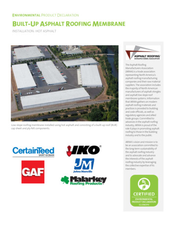
7.8.When converting an existing installation to a mechanicalseal, special attention must be placed on the conditionof the pump. All pumps should be inspected to makesure the rotor shaft is in good condition. Any shaft weardue to packing will result in mechanical seal leakage.In general, the rotor and shaft assembly should bereplaced. N size pumps can use the same rotor bearingsleeve assembly without modification. Outboard faceof this assembly will need to be cleaned to make surethere is a good surface for the mechanical seal to sealagainst.DISASSEMBLYDANGER !Before opening any Viking pump liquidchamber (pumping chamber, reservoir,relief valve adjusting cap fitting, etc.)Be sure:1. That any pressure in the chamber has beencompletely vented through the suctionor discharge lines or other appropriateopenings or connections.Most asphalt pumps are V-Belt driven. Packing is quitetolerant of any misalignment but mechanical seals arenot. Make sure sheaves are aligned properly (see TSM000) and that the rotor shaft is properly supported with apillow block bearing. It is also important to make sure themechanical seal is properly aligned with the rotor shaft.This is done at the time of seal installation. Be sure torecheck alignment when the rotor shaft is inserted in thepillow block bearing.2. That the driving means (motor, turbine,engine, etc.) has been “locked out” ormade non-operational so that it cannot bestarted while work is being done on pump.3. That you know what liquid the pumphas been handling and the precautionsnecessary to safely handle the liquid.Obtain a material safety data sheet (MSDS)for the liquid to be sure these precautionsare understood.PRESSURE RELIEF VALVEINSTRUCTIONSSeries 34 and 434 jacketed pumps may be furnished witha relief valve head and a plain or jacketed relief valve asillustrated in Figures 10 and 11.Failure to follow above listed precautionarymeasures may result in serious injury or death.Mark valve and head before disassembly to insure properreassembly.FIGURE 10PLAIN VALVE1.Remove valve cap.2.Measure and record length of extension of adjustingscrew. Refer to “A” on Figures 10 and 11.3.Loosen locknut and back out adjusting screw until springpressure is released.4.Remove bonnet, spring guide, spring and poppet fromvalve body. Clean and inspect all parts for wear ordamage and replace as necessary.ASSEMBLYFollow the procedure outlined under Disassembly in reverseorder.If valve is removed for repairs, be sure to replace in sameposition. The valve cap should point towards the suctionport.CAUTION !FIGURE 11Before starting the pump, be sure all driveequipment guards are in place.VALVE - LIST OF PARTSFailure to properly mount guards mayresult in serious injury or death.JACKETED VALVE1.Valve Cap6. Valve Body2.Adjusting Screw7.3.Lock Nut8. Poppet4.Spring Guide9.Cap Gasket5.Bonnet10Bonnet GasketSECTION TSM 430ISSUEIValve SpringPAGE 8 OF 9NOTE: HL, KK AND SERIES 434 SEALED PUMPSDISCONTINUED AS OF 1Q16.
TECHNICAL SERVICE MANUALJACKETED ASPHALT PUMPSSERIES 34 AND 434SIZES HL, KK, LQ, Q, M, NSECTIONTSM 430PAGE9 OF 9ISSUEIIMPORTANTIn ordering parts for relief valve on head, always be sureto give Model and Serial Number of pump as it appears onnameplate and the name of the part wanted. When orderingsprings, be sure to give the pressure setting desired.WARRANTYViking pumps, strainers and reducers are warranted to befree of defects in material and workmanship under normalconditions of use and service. The warranty period varies bytype of product. A Viking product that fails during its warrantyperiod under normal conditions of use and service due to adefect in material or workmanship will be repaired or replacedby Viking. At Viking’s sole option, Viking may refund (in cashor by credit) the purchase price paid to it for a Viking product(less a reasonable allowance for the period of use) in lieu ofrepair or replacement of such Viking product. Viking’s warrantyis subject to certain restrictions, limitations, exclusions andexceptions. A complete copy of Viking’s warranty, includingwarranty periods and applicable restrictions, limitations,exclusions and exceptions, is posted on Viking’s . A completecopy of the warranty may also be obtained by contactingViking through regular mail at Viking Pump, Inc., 406 StateStreet, Cedar Falls, Iowa 50613, USA.THIS WARRANTY IS AND SHALL BE VIKING’S SOLEAND EXCLUSIVE WARRANTY AND IS IN LIEU OFALL OTHER WARRANTIES, EXPRESS OR IMPLIED,INCLUDING, BUT NOT LIMITED TO, ALL WARRANTIESOF MERCHANTABILITY, FITNESS FOR A PARTICULARPURPOSE AND NON-INFRINGMENT, ALL OF WHICHOTHER WARRANTIES ARE EXPRESSLY EXCLUDED.THE RIGHTS AND REMEDIES UNDER THIS WARRANTYARE AND SHALL BE THE SOLE AND EXCLUSIVE RIGHTSAND REMEDIES AGAINST VIKING. EXCEPT FOR THESPECIFIC LIABILITIES AND OBLIGATIONS PROVIDEDUNDER THIS WARRANTY, VIKING SHALL HAVE NOLIABILITY OR OBLIGATION WITH RESPECT TO ANYPRODUCT CLAIMED TO BE DEFECTIVE IN ANY MANNER.UNDER NO CIRCUMSTANCES SHALL VIKING BELIABLE UNDER THIS WARRANTY OR OTHERWISE FORSPECIAL, INCIDENTAL, INDIRECT, CONSEQUENTIAL ORPUNITIVE DAMAGES OF ANY KIND, INCLUDING, BUT NOTLIMITED TO, LOST OR UNREALIZED SALES, REVENUES,PROFITS, INCOME, COST SAVINGS OR BUSINESS, LOSTOR UNREALIZED CONTRACTS, LOSS OF GOODWILL,DAMAGE TO REPUTATION, LOSS OF PROPERTY, LOSSOF INFORMATION OR DATA, LOSS OF PRODUCTION,DOWNTIME, OR INCREASED COSTS, IN CONNECTIONWITH ANY PRODUCT, EVEN IF VIKING HAS BEEN ADVISEDOR PLACED ON NOTICE OF THE POSSIBILITY OF SUCHDAMAGES AND NOTWITHSTANDING THE FAILURE OFANY ESSENTIAL PURPOSE OF ANY PRODUCT.NOTE: HL, KK AND SERIES 434 SEALED PUMPS DISCONTINUED AS OF 1Q16.VIKING PUMP, INC. A Unit of IDEX Corporation Cedar Falls, IA 50613 USA 12/2016 Viking Pump Inc.All rights reserved
Electronic copies of the most current TSM issue can be found on the Viking Pump website at www.vikingpump.com NOTE: The Technical Service Manual for the electrically heated pumps is located in the Universal Seal manuals: TSM 630.1 (H-LL sizes), TSM 630.2 (LS-QS sizes) and TSM 630.3 (N-RS sizes)