Transcription
Lecture 18:FeedbackGu-Yeon WeiDivision of Engineering and Applied SciencesHarvard Universityguyeon@eecs.harvard.eduWei1
Overview Reading– S&S: Chapter 8.1 8.8– S&S: Appendix B (Two-Port Network Parameters)Background– Negative feedback for amplifiers was invented in 1927 by Harold Black tostabilize the gain and correct the distortion of amplifiers used in longdistance telephone networks. Negative feedback (as well as positivefeedback) is widely used in analog circuits today. In fact, we used negativefeedback when we constructed op amps with gain set (fixed) usingresistors. Throughout the next lecture, we will investigate the generaltheory of feedback and look at four basic feedback topologies for four typesof amplifier topologies. We will return to concepts of feedback covered inChapter 8 of S&S after taking investigating how to build single- and twostage Op amps. We will return to material in Chapter 8 to study stability ofamplifiers, and see how “compensation” can be utilized.– S&S has several examples of circuits with feedback using BJTs. Theselecture notes give MOS circuit examples (many from Razavi’s textbook).WeiES154 - Lecture 182
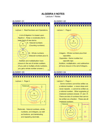
General Feedback StructureLet’s start with the basic structure of a feedback amplifier. To make it general, the figureshows signal flow as opposed to voltages or currents (i.e., signals can be either current orvoltage).SourcexsΣxiAxfβxoLoadThe open-loop amplifier has gain A Æ xo A*xi Output is fed back through a feedback network which produces a sample (xf) of the output(xo) Æ xf βxo– Where β is called the feedback factor The input to the amplifier is xi xs – xf (the subtraction makes feedback negative)– Implicit to the above analysis is that neither the feedback block nor the load affect theamplifier’s gain (A). This not generally true and so we will later see how to deal with it. The overall gain (closed-loop gain) can be solved to be:xAAf o xs 1 Aβ WeiAβ is called the loop gain and 1 Aβ is called the “amount of feedback”ES154 - Lecture 183
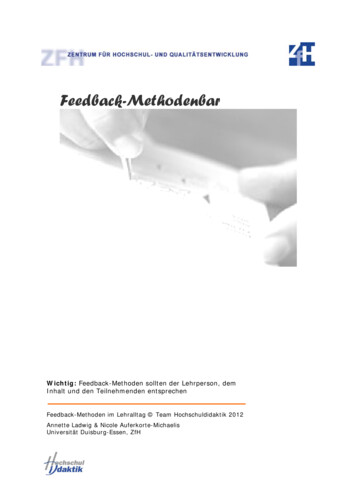
Finding Loop Gain Generally, we can find the loop gain with the following steps:– Break the feedback loop anywhere (at the output in the ex. below)– Zero out the input signal xs– Apply a test signal to the input of the feedback circuit– Solve for the resulting signal xo at the output If xo is a voltage signal, xtst is a voltage and measure the open-circuit voltage If xo is a current signal, xtst is a current and measure the short-circuit currentxs 0Σxix f β xtstAxi 0 x fxo Axi Ax f βAxtstxfβxtstxoloop gain xo βAxtst– The negative sign comes from the fact that we are apply negative feedbackWeiES154 - Lecture 184
Negative Feedback Properties WeiNegative feedback takes a sample of the output signal and applies it to the inputto get several desirable properties. In amplifiers, negative feedback can beapplied to get the following properties– Desensitized gain – gain less sensitive to circuit component variations– Reduce nonlinear distortion – output proportional to input (constant gainindependent of signal level)– Reduce effect of noise– Control input and output impedances – by applying appropriate feedbacktopologies– Extend bandwidth of amplifierAll of these properties can be achieved by trading off gainLet’s investigate a couple of these properties in a little more detail using thegeneral structure described in the previous slideES154 - Lecture 185
Gain Desensitivity Feedback can be used to desensitize the closed-loop gain to variations in thebasic amplifier. Let’s see how.Assume β is constant. Taking differentials of the closed-loop gain equationgives Af A1 AβdA f Take derivative ofboth sidesdA(1 Aβ )2– Divide by AfdA fAf dA 1 Aβ1 dA 21 Aβ A(1 Aβ ) A This result shows the effects of variations in A on Af is mitigated by the feedbackamount. 1 Aβ is also called the desensitivity amount We will see through examples that feedback also affects the input andresistance of the amplifier (increases Ri and decreases Ro by 1 Aβ factor)WeiES154 - Lecture 186
Bandwidth Extension We’ve mentioned several times in the past that we can trade gain for bandwidth.Finally, we see how to do so with feedback Consider an amplifier with a high-frequency response characterized by a singlepole and the expression:A(s ) AM1 s ωHApply negative feedback β and the resulting closed-loop gain is:A f (s ) WeiA(s )AM (1 AM β ) 1 βA(s ) 1 s ω H (1 AM β )Notice that the midband gain reduces by (1 AMβ) while the 3-dB roll-offfrequency increases by (1 AMβ)ES154 - Lecture 187
Basic Feedback Topologies Depending on the input signal (voltage or current) to be amplified and formof the output (voltage or current), amplifiers can be classified into fourcategories. Depending on the amplifier category, one of four types offeedback structures should be used (series-shunt, series-series, shuntshunt, or shunt-series)– Voltage amplifier – voltage-controlled voltage source –Current amplifier – current-controlled current source –series-shuntUse shunt-series feedback (current-current feedback)Transconductance amplifier – voltage-controlled current source –Requires high input impedance, low output impedanceUse series-shunt feedback (voltage-voltage feedback)Use series-series feedback (current-voltage feedback)Transimpedance amplifier – current-controlled voltage source Use shunt-shunt feedback (voltage-current 154 - Lecture 188
Examples of the Four Types of Amp hown above are simple examples of the four types of amplifiers. Often, these amplifiersalone do not have good performance (high output impedance, low gain, etc.) and areaugmented by additional amplifier stages (see below) or different configurations (e.g.,cascoding).iOUTRDRDvOUTvINVbRDWeiRDVbvOUT vINiINlower ZoutiOUTiINlower ZoutES154 - Lecture 18higher gainhigher gain9
Sense and Return Mechanisms Adding a feedback loop consists of sensing the output signal and returning (a fraction) of theresult to the summing node at the input.– Given the inputs and outputs can be either voltages or currents, there are four types offeedback: voltage-voltage, voltage-current, current-voltage, and current-current where the first part denotes the quantity sensed at the output and the second denotes the typeof signal returnedExamples of sensing voltage and current:ioutvoutioutRLvoltmetercurrent meterWeiES154 - Lecture 18RsenseRLvsense10
Sense and Return Cont’d Here are some circuit examples of sensing and returning voltages and currents:vinvoutvinvinR2vfioutvfR1voutR2vinVoltage R2R1IFCurrent returnRFWeiES154 - Lecture 1811
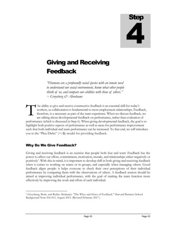
Series-Shunt Feedback Amplifier(Voltage-Voltage Feedback) Samples the output voltage and returns a feedbackvoltage signal– Ideal feedback network has infinite inputimpedance and zero output resistanceFind the closed-loop gain and input resistanceV f β VoVi Vs V fVo A(Vs β Vo )Af VoA Vs 1 β ARif VsVVV β AVi s Ri s Ri i Ri (1 Aβ )I i Vi RiViVi–The output resistance can be found by applying atest voltage to the outputRof Ro1 βASo, increases input resistance and reduces outputresistance Æ makes amplifier closer to ideal VCVSWeiES154 - Lecture 1812
Circuit Example Feedback can be constructed out of capacitorsFind the open-loop gain––– At low frequency, cap loads negligibleBreak feedback and zero out input to feedbackAssume Vf is at some DC bias equal to the DC value of vinM3vinM4M1fM2C1voutC2A g m (ro 2 ro 4 )Find the loop gain, closed-loop gain, and closed-loop RoutNoteNotecorrection:correction:vov and not vfand not vofvo C1g m1 (ro 2 ro 4 )vtstC1 C2vC1g m1 (ro 2 ro 4 )βA o vtst C1 C2Af A 1 βA 1 Rout ,closed Weig m1 (ro 2 ro 4 )C1g m1 (ro 2 ro 4 )C1 C2 C1 1 1 CC 12 g m1g m1 (ro 2 ro 4 ) ro 2 ro 41 C1C1 C2ES154 - Lecture 18M3M4M1M2vofitstC1C2Circuit to solve loop gain13vtst
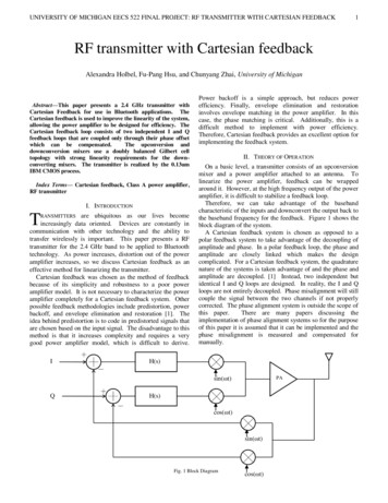
Series-Series Feedback Amplifier(Current-Voltage FB) For a transconductance amplifier (voltage input, currentoutput), we must apply the appropriate feedback circuit– Sense the output current and feedback a voltage signal.So, the feedback current is a transimpedance block thatconverts the current signal into a voltage.Af IoA Vs 1 AβA Io(also called Gm )ViTo solve for the loop gain:– Break the feedback, short out the break in the currentsense and applying a test currentLoop Gain Aβ To solve for Rif and RofI out Gm R fI tstV Vi V f Ri I i β I o Ri I i Aβ ViRif s Ri (1 Aβ )IiIiIiIi–Apply a test voltage Vtst across O and O’Rof WeiIoutGmZLItstVfRFVtst (I tst AVi )Ro (I tst Aβ I tst )Ro (1 Aβ )RoI tstI tstI tstES154 - Lecture 1814
Circuit Example Source degeneration (with RF) is a form of current-voltage FB– Voltage across the resistor is the feedback voltage VF subtracts from Vin to reduce Vgs of the nMOSIout– Without the feedback R, iout/vin gm Æ A gm– RF is the feedback circuit that senses the output currentand subtracts a voltage from the inputVin VF βIout Æ β RFVFRFiout g m v gs g m (vin iout RF )iout (1 g m RF ) g m vinAf gmvgsioutgmA vin 1 Aβ 1 g m RFvinvgsIoutroRFWeiES154 - Lecture 1815
Shunt-Shunt Feedback Amplifier(Voltage-Current FB) When voltage-current FB is applied to atransimpedance amplifier, output voltage issensed and current is subtracted from the input– The gain stage has some resistance– The feedback stage is a tranconductorA VoIiVo βVoAVAAf o I s 1 AβI s Ii I f – Input and output resistances (Rif and Rof)follow the same form as before based onvalues for A and βWeiES154 - Lecture 18Rif Ri (1 Aβ )Rof Ro(1 Aβ )16
Circuit Example Transimpedance gain stage is through M2 (a common-baseamplifier) and feedback is thru the capacitor divider and M1(transconductor). Solve for A, Aβ, and Af.– vgs is whatever voltage necessary for iinA –vout iin RD RDiiniinRDC1M2VbVoutM1IinC2Loop gain is found by breaking loop and applying VtstvF C1vtstC1 C2voutgm vgsRDvgsi1 g m vFvout -i1 RDAβ –Small-signalcircuit tosolve for Aiinvout g m RD C1 (C1 C2 ) vtstC1 g m RDvtstvtstC1 C2Circuit tofind AβRDClosed-loop gain is justAf VtstvoutARD C1iin 1 Aβ 1 g Rm DC1 C2C1VbM2M1C2WeiES154 - Lecture 1817Vout
Shunt-Series Feedback Amplifier(Current-Current FB) A current-current FB circuit is used for currentamplifiers– For the β circuit – input resistance shouldbe low and output resistance be high A circuit example is shown– RS and RF constitute the FB circuit –WeiRS should be small and RF largeThe same steps can be taken to solve forA, Aβ, Af, Rif, and Rof IoutRDRemember that both A and β circuits arecurrent controlled current sourcesES154 - Lecture 18IinRFRS18
Effects of Loading So far, we have assumed that the feedback circuit does not load the feedforward (openloop) amplifier at the input or the output. In reality, this is not the case. Loading may not benegligible and complicate analysis.In order to properly model loading effects, we should first review models of two-portnetworks. The feedback circuit can be considered to be a two-port network that senses andproduces currents or voltages. The following are four types of linear two-port networks usingZ, Y, or H or G (impedance, admittance, or hybrid) modelsI1 Z11Z22 I2Z12I2V1WeiV2Z21I1V1 Y11I2Y12V2Y21V1V1 Z11 I1 Z12 I 2I1 Y11V1 Y12V2V2 Z 21 I1 Z 22 I 2I 2 Y21V1 Y22V2I1 H11V1I1H12V2H21I1I2I1H22 V2V1 G11G22 I2G12I2G21V1V1 H11 I1 H12V2I1 G11V1 G12 I 2I 2 H 21 I1 H 22V2V2 G21V1 G22 I 2ES154 - Lecture 18Y22 V2V219
Loading in Series-Shunt (Voltage-Voltage) FB Which is the best model to use?– Ideally, want infinite input resistance and zerooutput resistance Æ G-model– G12I2 contribution to Vout is small compared toamplification A so ignore G12 current source VinVereverse transmission thru the FB circuit is madepurposely smallZ inGA 1Z in G22 G11 Z out In the limit (ideal case), 1/G11 and G22 0 thenequation reduces to Af WeiAA 1 Aβ 1 AG21 VoutVinAVeG12I2 111ZoutVoutI1G21VoutV2 111ZinI2 G22Computer the closed-loop gain Z inVe (Vin G21Vout )Z in G22Vout (Vin G21Vout ) IinG11 0Z inG 1Z in G22 G11 Z out Z inG11 11 AG21Z in G22 G11 1 Z outAWe can retain this form for closed-loop gain bysolving for the open-loop gain that takes loadinginto accountES154 - Lecture 1820
Open-Loop Gain with Loading For the previous example, proper method forincluding loading to calculate the open-loop gainis shownVinConceptually, the approach is VinAβG22VeZinAVeZoutVoutVoutG11G22β1/G11– add load both sides (input and output) withthe feedback circuit– short the input of the β circuit that loads theinput of the amplifier– leave the output unconnected for the βcircuit that loads the output of the amplifier– Calculate the open-loop gainWeiIinES154 - Lecture 18G11 I1V1and G22 I 2 0V2I2V1 021
Summary of FB Types and 2-Port Models There is an appropriate 2-port model to use for each of thefeedback types (in table)A conceptual summary of solving for the open-loop gain withfeedback loading effects are as follows– Attach separate feedback circuits to both input andoutput (individually) as it would normally be connected– For the feedback circuit attached to the input (of theamplifier), zero out the other side of the feedback circuit(input port) –2-port ModelSeries-Shunt(Voltage-Voltage)G ModelSeries-Series(Current-Voltage)Z ModelShunt-Shunt(Voltage-Current)Y ModelShunt-Series(Current-Current)H ModelFor the feedback circuit attached to the output (of theamplifier), leave the other side disconnected If input port to β circuit is a voltage, attach to a 0-Volt sourceIf input port to β circuit is a current, attach to a 0-Amp sourceFeedback TypeIf output port of β circuit is a voltage, leave as open circuitIf output port of β circuit is a current, short output to groundLet’s look at some examples of how to break the feedbackand determine the open-loop gain that includes the effects offeedback.WeiES154 - Lecture 1822
Loading in Series-Shunt (Voltage-Voltage) FB β circuitRS M2VinRD2M1RFRSVopenRFRSRD2The open-loop gain (with loading) can be calculated to beAopen loop WeiRD1VopenVin RD1{ g m 2 [RD 2 (RF RS )]}RF RS 1 g m1ES154 - Lecture 1823
Loading in Series-Series (Current-Voltage) FB ExampleA penM2VinRD2Z11M1M3RD2RFRS1 RFβ circuitRS3RS1RS3The open-loop gain (transconductance) can be solved to be:Aopen loop WeiRS1RS3RFI openVin g m 2 RD 2 RD1(RF RS 3 ) RS1 1 g m1 (RF RS1 ) RS 3 1 g m3ES154 - Lecture 1824
Loading in Shunt-Shunt (Voltage-Current) FB ExampleA Vout/IeIeIinAVoutVinAβββ1/Y22β circuitIin RDVoutRFRSIinRFVoutRSThe open-loop gain (transimpedance) can be solved to be:Aopen loop Wei1/Y11RDRFVopenVopenI in g m (RS RF )(RD RF )ES154 - Lecture 1825
Loading in Shunt-Series (Current-Current) FB ExampleA Iout/IeIinIeAIinIoutAββIopenβ1/H22RDIoutIinβ circuitRFRSRSRFRSThe open-loop (current) gain be solved to be:Aopen loop WeiIopenRDIinRF H11I openI in g m (RS RF )RDES154 - Lecture 181RF RS 1 g m 226
Next Time Reading– S&S Chapter 10.7 10.8 What to look forward to – We will shift gears a little bit and look at a few approaches for buildingCMOS Operational Amplifiers. We will begin with single-stage op amps andthe proceed to two-stage op amps and some of their advantages anddisadvantages.– The investigation of op amp designs with multiple poles forces us to thendeal with stability issues. The final lecture will cover stability andcompensation in amplifier design. Reading for the final lecture is S&SChapter 8.8 8.11.WeiES154 - Lecture 1827
- Sense the output current and feedback a voltage signal. So, the feedback current is a transimpedance block that converts the current signal into a voltage. To solve for the loop gain: - Break the feedback, short out the break in the current sense and applying a test current To solve for R if and R of - Apply a test voltage V