Transcription
Spec SheetCisco UCS C240 M4High-DensityRack Server (Large FormFactor Disk Drive Model)CISCO SYSTEMS170 WEST TASMAN DR.SAN JOSE, CA, 95134WWW.CISCO.COMPUBLICATION HISTORYREV C.4JULY 15, 2015
CONTENTSOVERVIEW . . . . . . . . . . . . . . . . . . . . . . . . . . . . . . . . . . . . . . . . . . . . . . . 5DETAILED VIEWS . . . . . . . . . . . . . . . . . . . . . . . . . . . . . . . . . . . . . . . . . . . 6Chassis Front View . . . . . . . . . . . . . . . . . . . . . . . . . . . . . . . . . . . . . . . . . . . . . . . . . . .6Chassis Rear View . . . . . . . . . . . . . . . . . . . . . . . . . . . . . . . . . . . . . . . . . . . . . . . . . . .7BASE SERVER STANDARD CAPABILITIES and FEATURES . . . . . . . . . . . . . . . . . 8CONFIGURING the SERVER . . . . . . . . . . . . . . . . . . . . . . . . . . . . . . . . . . . 12STEP 1 VERIFY SERVER SKU . . . . . . . . . . . . . . . . . . . . . . . . . . . . . . . . . . . . . . . . . . . 13STEP 2 SELECT RISER CARDS (OPTIONAL) . . . . . . . . . . . . . . . . . . . . . . . . . . . . . . . . . . 14STEP 3 SELECT CPU(s) . . . . . . . . . . . . . . . . . . . . . . . . . . . . . . . . . . . . . . . . . . . . . . 15STEP 4 SELECT MEMORY . . . . . . . . . . . . . . . . . . . . . . . . . . . . . . . . . . . . . . . . . . . . . 17STEP 5 SELECT RAID CONTROLLERS . . . . . . . . . . . . . . . . . . . . . . . . . . . . . . . . . . . . . 22RAID Controller Option (internal HDD/SSD support) . . . . . . . . . . . . . . . . . . . . . . . . . . . . 22Cisco 12G SAS Modular RAID Controller . . . . . . . . . . . . . . . . . . . . . . . . . . . . . . . . 22SAS HBA (internal HDD/SSD/JBOD support) . . . . . . . . . . . . . . . . . . . . . . . . . . . . . . . . . . 22SAS HBA (external JBOD support) . . . . . . . . . . . . . . . . . . . . . . . . . . . . . . . . . . . . . . . . 22RAID Volumes and Groups . . . . . . . . . . . . . . . . . . . . . . . . . . . . . . . . . . . . . . . . . . . . . 22STEP 6 SELECT HARD DISK DRIVES (HDDs) . . . . . . . . . . . . . . . . . . . . . . . . . . . . . . . . . 27STEP 7 SELECT PCIe OPTION CARD(s) . . . . . . . . . . . . . . . . . . . . . . . . . . . . . . . . . . . . 30STEP 8 ORDER OPTIONAL NETWORK CARD ACCESSORIES . . . . . . . . . . . . . . . . . . . . . . . . 34STEP 9 ORDER GPU CARDS(OPTIONAL) . . . . . . . . . . . . . . . . . . . . . . . . . . . . . . . . . . . 38STEP 10 ORDER POWER SUPPLY . . . . . . . . . . . . . . . . . . . . . . . . . . . . . . . . . . . . . . . . 41STEP 11 SELECT AC POWER CORD(s) . . . . . . . . . . . . . . . . . . . . . . . . . . . . . . . . . . . . . 42STEP 12 ORDER TOOL-LESS RAIL KIT AND OPTIONAL REVERSIBLE CABLE MANAGEMENT ARM . 45STEP 13 SELECT NIC MODE (OPTIONAL) . . . . . . . . . . . . . . . . . . . . . . . . . . . . . . . . . . . 46STEP 14 ORDER A TRUSTED PLATFORM MODULE (OPTIONAL) . . . . . . . . . . . . . . . . . . . . . 47STEP 15 ORDER CISCO FLEXIBLE FLASH SD CARD MODULE (OPTIONAL) . . . . . . . . . . . . . . . 48STEP 16 ORDER OPTIONAL USB 3.0 DRIVE . . . . . . . . . . . . . . . . . . . . . . . . . . . . . . . . . 49STEP 17 SELECT OPERATING SYSTEM AND VALUE-ADDED SOFTWARE . . . . . . . . . . . . . . . . 50STEP 18 SELECT OPERATING SYSTEM MEDIA KIT . . . . . . . . . . . . . . . . . . . . . . . . . . . . . 53STEP 19 SELECT SERVICE and SUPPORT LEVEL . . . . . . . . . . . . . . . . . . . . . . . . . . . . . . 54OPTIONAL STEP - ORDER RACK(s) . . . . . . . . . . . . . . . . . . . . . . . . . . . . . . 59OPTIONAL STEP - ORDER PDU . . . . . . . . . . . . . . . . . . . . . . . . . . . . . . . . . 60SUPPLEMENTAL MATERIAL . . . . . . . . . . . . . . . . . . . . . . . . . . . . . . . . . . . 61CHASSIS . . . . . . . . . . . . . . . . . . . . . . . . . . . . . . . . . . . . . . . . . . . . . . . . . . . . . . . . . 61Block Diagram . . . . . . . . . . . . . . . . . . . . . . . . . . . . . . . . . . . . . . . . . . . . . . . . . . . . . 63CPUs and DIMMs . . . . . . . . . . . . . . . . . . . . . . . . . . . . . . . . . . . . . . . . . . . . . . . . . . . . 64Physical Layout . . . . . . . . . . . . . . . . . . . . . . . . . . . . . . . . . . . . . . . . . . . . . . . . 64Memory Population Rules . . . . . . . . . . . . . . . . . . . . . . . . . . . . . . . . . . . . . . . . . 65DIMM Population Order . . . . . . . . . . . . . . . . . . . . . . . . . . . . . . . . . . . . . . . . . . . 66Recommended Memory Configuration . . . . . . . . . . . . . . . . . . . . . . . . . . . . . . . . . 67Additional DIMM Populations . . . . . . . . . . . . . . . . . . . . . . . . . . . . . . . . . . . . . . . 68RAID Details . . . . . . . . . . . . . . . . . . . . . . . . . . . . . . . . . . . . . . . . . . . . . . . . . . . . . . 69Cisco 12G SAS Modular RAID Controller (RAID Support) . . . . . . . . . . . . . . . . . . . . . . 69Cisco 12 Gbps SAS HBA (JBOD Only Support) . . . . . . . . . . . . . . . . . . . . . . . . . . . . . 69RAID Option ROM (OPROM) Settings . . . . . . . . . . . . . . . . . . . . . . . . . . . . . . . . . . . . . . . 70Riser Card Configuration and Options . . . . . . . . . . . . . . . . . . . . . . . . . . . . . . . . . . . . . 71Serial Port Details . . . . . . . . . . . . . . . . . . . . . . . . . . . . . . . . . . . . . . . . . . . . . . . . . . 73Upgrade and Servicing-Related Parts . . . . . . . . . . . . . . . . . . . . . . . . . . . . . . . . . . . . . . 74Adding an Additional CPU (with CPU heat sink) or Replacing CPUs . . . . . . . . . . . . . . 752Cisco UCS C240 M4 High-Density Rack Server (Large Form Factor Disk Drive Model)
Motherboard Lithium Battery . . . . . . . . . . . . . . . . . . . . . . . . . . . . . . . . . . . . . . . 75Thermal Grease (with syringe applicator) for CPU to Heatsink Seal . . . . . . . . . . . . . . 75Air Baffle Replacement Kit . . . . . . . . . . . . . . . . . . . . . . . . . . . . . . . . . . . . . . . . 76CPU Heat Sink Cleaning Kit . . . . . . . . . . . . . . . . . . . . . . . . . . . . . . . . . . . . . . . . 76RACKS . . . . . . . . . . . . . . . . . . . . . . . . . . . . . . . . . . . . . . . . . . . . . . . . . . . . . . . . . . 77PDUs . . . . . . . . . . . . . . . . . . . . . . . . . . . . . . . . . . . . . . . . . . . . . . . . . . . . . . . . . . . 79KVM CABLE . . . . . . . . . . . . . . . . . . . . . . . . . . . . . . . . . . . . . . . . . . . . . . . . . . . . . . . 80Motherboard USB and SD Ports, and RAID Card Backup Locations . . . . . . . . . . . . . . . . . . . 81TECHNICAL SPECIFICATIONS . . . . . . . . . . . . . . . . . . . . . . . . . . . . . . . . . . 82Dimensions and Weight . . . . . . . . . . . . . . . . . . . . . . .Power Specifications . . . . . . . . . . . . . . . . . . . . . . . .Environmental Specifications . . . . . . . . . . . . . . . . . . .Compliance Requirements . . . . . . . . . . . . . . . . . . . . .Cisco UCS C240 M4 High-Density Rack Server (Large Form Factor Disk Drive Model). . 82. . 83. . 85. . 873
CONTENTS4Cisco UCS C240 M4 High-Density Rack Server (Large Form Factor Disk Drive Model)
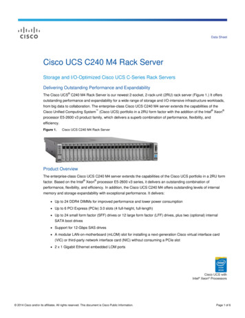
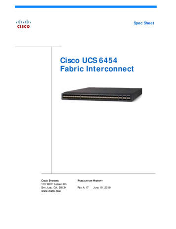
OVERVIEWOVERVIEWThe UCS C240 M4 LFF server is the newest 2-socket, 2U rack server from Cisco, designed for bothperformance and expandability over a wide range of storage-intensive infrastructure workloads from bigdata to collaboration.The enterprise-class UCS C240 M4 SFF server extends the capabilities of Cisco’s Unified Computing Systemportfolio in a 2U form factor with the addition of the Intel Xeon E5-2600 v3 series processor family thatdelivers the best combination of performance, flexibility and efficiency gains. In addition, the UCS C240 M4LFF server provides 24 DIMM slots, up to 6 PCI Express (PCIe) 3.0 slots, up to 12 front-loading LFF drives plustwo (optional) internal SFF SATA boot drives for a total of 14 internal drives.The C240 M4 server includes a modular LAN on motherboard (mLOM) slot for installation of a Cisco VirtualInterface Card (VIC) or third-party network interface card (NIC) without consuming a PCI slot in addition to2 x 1 GbE embedded (on the motherboard) LOM ports. These features combine to provide outstanding levelsof internal memory and storage expandability along with exceptional performance.The Cisco UCS C240 M4 server can be used standalone, or as part of the Cisco Unified Computing System,which unifies computing, networking, management, virtualization, and storage access into a singleintegrated architecture enabling end-to-end server visibility, management, and control in both bare metaland virtualized environments.Figure 1Cisco UCS C240 M4 High-Density LFF Rack ServerFront ViewRear ViewCisco UCS C240 M4 High-Density Rack Server (Large Form Factor Disk Drive Model)5
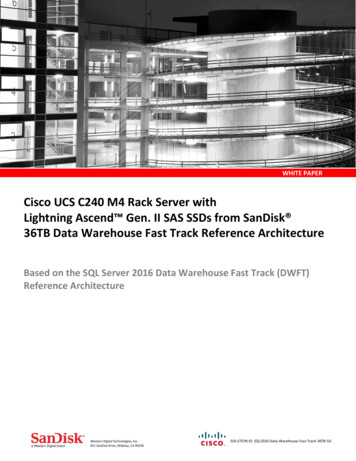
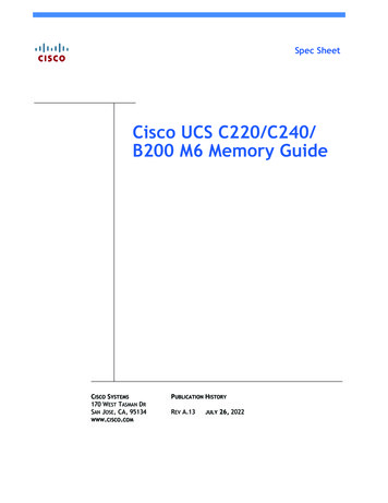
DETAILED VIEWSDETAILED VIEWSChassis Front ViewFigure 2 shows the 12-drive Cisco UCS C240 M4 High-Density LFF Rack Server.Figure 2Chassis Front View2HDD 01HDD 02HDD 03HDD 04HDD 05HDD 06HDD 07HDD 08HDD 09HDD 10HDD 11HDD 123529461103114567891Drive bays 1–12 (up to 12 3.5-inch drives)7Temperature status LED2Operations panel buttons and LEDs8Power supply status LED3Power button/LED9Network link activity LED4Unit Identification button/LED10Pull-out asset tag5System status LED11KVM connector(used with KVM cable that provides two USB2.0 connectors, one VGA connector, and oneserial connector)6Fan status LEDFor more information about the KVM cable connection, see KVM CABLE, page 80.6Cisco UCS C240 M4 High-Density Rack Server (Large Form Factor Disk Drive Model)
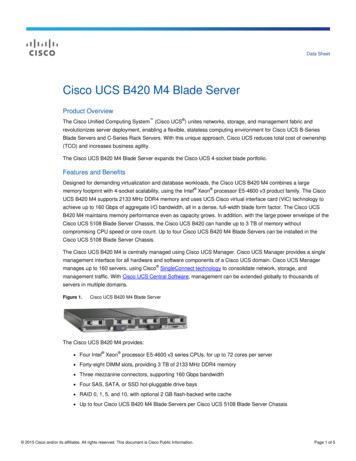
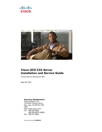
DETAILED VIEWSChassis Rear ViewFigure 3 shows the external features of the rear panel.Chassis Rear View132PCIe 03PCIe 06PCIe 02PCIe 05PCIe 01PCIe 04PSU 0211PSU 01mLOM415678PCIe riser 1 (slots 1, 2, 3*)9352947Figure 3107Serial connector (RJ-45)1PCIe riser 2 (slots 4, 5, 6), See Riser CardConfiguration and Options, page 71 fordetails.8Two embedded (on the motherboard) Inteli350 GbE Ethernet controller ports3Power supplies (DC power supplies shown)9VGA video port (DB-15 connector)4Modular LAN-on-motherboard (mLOM) cardslot10Rear Unit Identification button/LED5USB 3.0 ports (two)11Grounding-lug holes (for DC power supplies)61-Gb dedicated management port*Slot 3 not present in all versions. See RiserCard Configuration and Options, page 71for details.2(LAN1, LAN2)—Notes . . .1. For serial port pinout details, see Serial Port Details, page 73Cisco UCS C240 M4 High-Density Rack Server (Large Form Factor Disk Drive Model)7
BASE SERVER STANDARD CAPABILITIES and FEATURESBASE SERVER STANDARD CAPABILITIES and FEATURESTable 1 lists the capabilities and features of the base server. Details about how to configure the server fora particular feature or capability (for example, number of processors, disk drives, or amount of memory)are provided in CONFIGURING the SERVER, page 12.Table 1 Capabilities and FeaturesCapability/FeatureDescriptionChassisTwo rack unit (2RU) chassisCPUOne or two Intel Xeon E5-2600 v3 series processor family CPUsChipsetIntel C610 series chipsetMemory24 slots for registered ECC DIMMs (RDIMMs) or load-reduced DIMMs (LRDIMMs)Multi-bit ErrorProtectionThis server supports multi-bit error protection.Expansion slotsUp to six PCIe slots (on two riser cards) Riser 1 (PCIe slots 1, 2, and 3), controlled by CPU 1. Option A: Two slots available. Slot 1 full height, 3/4 length, x8, NCSI1.Slot 2 full height, full length, x16, NCSI, GPU capable. NCSI is supportedon only one slot at a time. Option B: Three slots available. Slot 1 full height, 3/4 length, x8. Slot 2 full height, full length, x8, NCSI. Slot 3 full height, full length, x8. Option C: Two slots available. Slot 1 full height, 3/4 length, x8, NCSI.Slot 2 full height, full length, x16, NCSI. In addition, the riser containstwo connectors for connecting up to two SATA boot drives. Riser 2 (PCIe slots 4, 5, and 6), controlled by CPU 2. Three slots available.Slot 4 full height, 3/4 length, x8, NCSI. Slot 5 full height, full length, x16,NCSI, GPU capable. Slot 6 full height, full length, x8. NCSI is supported ononly one slot at a time.Dedicated RAID controller slot (see Figure 6 on page 61) An internal slot is reserved for the 12G SAS Modular RAID controller card(see Figure 6 on page 61).For more details on riser 1 and riser 2 see Riser Card Configuration andOptions, page 71.VideoThe Cisco Integrated Management Controller (CIMC) provides video using theMatrox G200e video/graphics controller: 8Integrated 2D graphics core with hardware accelerationDDR2/3 memory interface supports up to 512 MB of addressable memory (8 MBis allocated by default to video memory) Supports display resolutions up to 1920 x 1200 16bpp @ 60Hz High-speed integrated 24-bit RAMDAC Single lane PCI-Express host interface running at Gen 1 speedCisco UCS C240 M4 High-Density Rack Server (Large Form Factor Disk Drive Model)
BASE SERVER STANDARD CAPABILITIES and FEATURESCapability/FeatureDescriptionInternal storagedevicesDrives are installed into front-panel drive bays that provide hot-pluggable access.Cisco Flexible Flashdrives Large Form Factor (LFF) drives. The server can hold up to 12 3.5-inch SAShard disk drives (HDDs). The server uses a 12-drive backplane with a SASexpander. Additionally, two optional internal 2.5 inch SATA SSDs can beinstalled for booting an OS. The server also contains one internal USB 3.0 port on the motherboard thatyou can use with an optional 16 GB USB thumb drive for additional storage UCS Storage Accelerators are also available. These plug-in PCIe flash storagecards provide independent high-speed storage.The server supports up to two internal 32 GB or two internal 64 GB Cisco FlexibleFlash drives (SD cards).The second SD card is blank and can be used to mirror the first SD card. It can beused to protect the Hypervisor Partition with RAID1.Interfaces Rear panel One DB15 VGA connector One RJ45 serial port connector Two USB 3.0 port connectors One RJ-45 10/100/1000 Ethernet management port, using Cisco IntegratedManagement Controller (CIMC) firmware Two Intel i350 embedded (on the motherboard) GbE LOM ports One flexible modular LAN on motherboard (mLOM) slot that canaccommodate various interface cards Various PCIe card ports (dependent on which cards are installed) Virtual Interface Card (VIC) ports Converged Network Adapter (CNA) ports Network Interface Card (NIC) ports Host Bus Adapter (HBA) ports Front panel One KVM console connector (supplies two USB 2.0 connectors, one VGADB15 video connector, and one serial port (RS232) RJ45 connector)Power subsystemUp to two of the following hot-swappable power supplies: 650 W (AC) 930 W (DC) 1200 W (AC) 1400 W (AC)One power supply is mandatory; one more can be added for 1 1 redundancy.Cisco UCS C240 M4 High-Density Rack Server (Large Form Factor Disk Drive Model)9
BASE SERVER STANDARD CAPABILITIES and FEATURESCapability/FeatureStorage controllerDescription Cisco 12G SAS Modular RAID controller card with internal SAS connectivity. Supports up to 24 internal drives (note however that this server can beconfigured with a maximum of 12 drives) Plugs into a dedicated RAID controller slotCan be purchased alone, or along with an onboard Flash-Backed WriteCache (FBWC) upgrade option, as shown in the table belowRAID Card VersionSupported RAID LevelsOnboard TMM CacheUCSC-MRAID12G1JBOD, 0, 1, 10NoneUCSC-MRAID12G-1GB2JBOD, 0, 1, 10, 5, 6, 50, 601 GBUCSC-MRAID12G-2GB2JBOD, 0, 1, 10, 5, 6, 50, 602 GBUCSC-MRAID12G-4GB2JBOD, 0, 1, 10, 5, 6, 50, 604 GBNotes . . .1. Base RAID controller card (RAID 0, 1, 10 only)2. FBWC option for base RAID controller card (adding the FBWC option extends theRAID levels)All versions of the UCSC-MRAID12G RAID controller support up to 24 internal SASdrives (limited to 12 drives for this server). Cisco 12 Gbps Modular SAS HBA with internal SAS connectivity Supports up to 24 internal drives (note however that this server can beconfigured with a maximum of 12 drives) Plugs into a dedicated PCIe slot at the rear of the server (slot 1 of riser 1) Supports JBOD only, not RAID, as shown in the below table. HBA Card VersionSupported RAID LevelsUCSC-SAS12GHBAJBOD onlyCisco 9300-8E 12G SAS HBA with external SAS connectivity Provides 8 external SAS ports Plugs into a PCIe slot at the rear of the server No FBWC (cache) or cache power backup SAS 3.0 compliant10Cisco UCS C240 M4 High-Density Rack Server (Large Form Factor Disk Drive Model)
BASE SERVER STANDARD CAPABILITIES and FEATURESCapability/FeatureEmbedded NICModular LAN onMotherboard(mLOM) slotDescriptionTwo embedded (on the motherboard) Intel i350 GbE ports, supporting thefollowing: Pre-Execution Boot (PXE boot) iSCSI boot Checksum and segmentation offload NIC teamingThe mLOM slot can flexibly accommodate the following cards: Cisco Virtual Interface Cards (VIC) Quad Port Intel i350 1GbE RJ45 Network Interface Card (NIC)NOTE: The four Intel i350 ports are provided on an optional cardthat plugs into the mLOM slot, and are separate from the two embedded(on the motherboard) LAN portsWoLFront PanelThe 1-Gb Base-T Ethernet LAN ports support the wake-on-LAN (WoL) standard. A front panel controller provides status indications and control buttonsACPIThis server supports the advanced configuration and power interface (ACPI) 4.0standard.FansChassis: Six hot-swappable fans for front-to-rear coolingIntegratedmanagementprocessorBaseboard Management Controller (BMC) running Cisco Integrated ManagementController (CIMC) firmware.Boot drivesUp to two optional SATA drives can be installed internal to the chassis on riser 1.The two SATA boot drives are managed in AHCI mode, using OS-based softwareRAID.Depending on your CIMC settings, the CIMC can be accessed through the 1-GbEdedicated management port, the 1-GbE LOM ports, or a Cisco virtual interfacecard (VIC).Notes . . .1. NCSI Network Communications Services Interface protocol. An NCSI slot is powered even when the server is instandby power mode.Cisco UCS C240 M4 High-Density Rack Server (Large Form Factor Disk Drive Model)11
CONFIGURING the SERVERCONFIGURING the SERVERFollow these steps to configure the Cisco UCS C240 M4 High-Density LFF Rack Server:12 STEP 1 VERIFY SERVER SKU, page 13 STEP 2 SELECT RISER CARDS (OPTIONAL), page 14 STEP 3 SELECT CPU(s), page 15 STEP 4 SELECT MEMORY, page 17 STEP 5 SELECT RAID CONTROLLERS, page 22 STEP 6 SELECT HARD DISK DRIVES (HDDs), page 27 STEP 7 SELECT PCIe OPTION CARD(s), page 30 STEP 8 ORDER OPTIONAL NETWORK CARD ACCESSORIES, page 34 STEP 9 ORDER GPU CARDS(OPTIONAL), page 38 STEP 10 ORDER POWER SUPPLY, page 41 STEP 11 SELECT AC POWER CORD(s), page 42 STEP 12 ORDER TOOL-LESS RAIL KIT AND OPTIONAL REVERSIBLE CABLE MANAGEMENTARM, page 45 STEP 13 SELECT NIC MODE (OPTIONAL), page 46 STEP 14 ORDER A TRUSTED PLATFORM MODULE (OPTIONAL), page 47 STEP 15 ORDER CISCO FLEXIBLE FLASH SD CARD MODULE (OPTIONAL), page 48 STEP 16 ORDER OPTIONAL USB 3.0 DRIVE, page 49 STEP 17 SELECT OPERATING SYSTEM AND VALUE-ADDED SOFTWARE, page 50 STEP 18 SELECT OPERATING SYSTEM MEDIA KIT, page 53 STEP 19 SELECT SERVICE and SUPPORT LEVEL, page 54 OPTIONAL STEP - ORDER RACK(s), page 59 OPTIONAL STEP - ORDER PDU, page 60Cisco UCS C240 M4 High-Density Rack Server (Large Form Factor Disk Drive Model)
CONFIGURING the SERVERSTEP 1VERIFY SERVER SKUSelect one server product ID (PID) from Table 2.Table 2 PID of the C240 M4 High-Density LFF Rack Base ServerProduct ID (PID)UCSC-C240-M4LDescriptionUCS C240 M4 LFF, no CPU, memory, HDD, SSD, PCIe cards, tool-less rail kit, orpower supply, with 12-drive backplane with SAS expanderThe Cisco UCS C240 M4 server: Does not include power supply, CPU, memory, hard disk drives (HDDs), solid-state drives(SSDs), boot drives, SD cards, riser 1, riser 2, tool-less rail kit, or PCIe cards.NOTE: Use the steps on the following pages to configure the server withthe components that you want to include.Cisco UCS C240 M4 High-Density Rack Server (Large Form Factor Disk Drive Model)13
CONFIGURING the SERVERSTEP 2SELECT RISER CARDS (OPTIONAL)There are two optional riser cards, riser card 1 and 2. There are three options for riser card 1.Order one riser card 1 from Table 2 and one riser 2 card from Table 3. Riser card 1 is the one onthe left when viewed form the back of the server and riser card 2 is on the right.Table 3 PID of the Riser 1 CardProduct ID (PID)DescriptionUCSC-PCI-1A-240M4C240 M4 PCIe Riser 1 Assy (option A)(2 PCIe slots: 1x8 and 1x16 GPU capable)UCSC-PCI-1B-240M4C240 M4 PCIe Riser 1 Assy (option B)(3 PCIe slots: 3x8)UCSC-PCI-1C-240M4C240 M4 PCIe Riser 1 Assy (option C)(2 PCIe slots: 1x8 and 1x16 plus connectors for 2 SATA boot drives)The selection of riser card 1 determines the number and type of PCIe cards and SATA boot drivessupported in the riser.Table 4 PID of the Riser 2 CardProduct ID (PID)UCSC-PCI-2-C240M4DescriptionLeft PCIe Riser Board (Riser 2) for C240 M4 (3 slots: 2x8 and 1x16)For additional details, see Riser Card Configuration and Options, page 71.14Cisco UCS C240 M4 High-Density Rack Server (Large Form Factor Disk Drive Model)
CONFIGURING the SERVERSTEP 3SELECT CPU(s)The standard CPU features are: Intel Xeon E5-2600 v3 series processor family CPUsIntel C610 series chipsetCache size of up to 45 MBSelect CPUsThe available CPUs are listed in Table 5.Table 5 Available Intel CPUs: E5-2600 v3 Series Processor Family CPUsPower(W)CacheSize(MB)CoresQPIHighestDDR4 DIMMClockSupport(MHz)12.3014545189.6 GT/s2133E5-2698 v32.3013540169.6 GT/s2133UCS-CPU-E52697DE5-2697 v32.6014535149.6 GT/s2133UCS-CPU-E52695DE5-2695 v32.3012035149.6 GT/s2133UCS-CPU-E52690DE5-2690 v32.6013530129.6 GT/s2133UCS-CPU-E52683DE5-2683 v32.0012035149.6 GT/s2133UCS-CPU-E52680DE5-2680 v32.5012030129.6 GT/s2133UCS-CPU-E52670DE5-2670 v32.3012030129.6 GT/s2133UCS-CPU-E52667DE5-2667 v33.201352089.6 GT/s2133UCS-CPU-E52660DE5-2660 v32.6010525109.6 GT/s2133UCS-CPU-E52658DE5-2658 v32.2010530129.6 GT/s2133UCS-CPU-E52650DE5-2650 v32.3010525109.6 GT/s2133UCS-CPU-E52650LDE5-2650L v31.806530129.6 GT/s1866UCS-CPU-E52643DE5-2643 v33.401352069.6 GT/s2133UCS-CPU-E52640DE5-2640 v32.60902088.0 GT/s1866UCS-CPU-E52637DE5-2637 v33.501351549.6 GT/s2133UCS-CPU-E52630DE5-2630 v32.40852088.0 GT/s1866UCS-CPU-E52630LDE5-2630L v31.80552088.0 GT/s1866UCS-CPU-E52623DE5-2623 v33.001051048.0 GT/s1866UCS-CPU-E52620DE5-2620 v32.40851568.0 GT/s1866UCS-CPU-E52609D2E5-2609 v31.90851566.4 -2699 v3UCS-CPU-E52698DProduct ID (PID)Notes . . .1. If higher or lower speed DIMMs are selected than what is shown in the table for a given CPU, the DIMMs will beclocked at the lowest common denominator of CPU clock and DIMM clock.2. The E5-2609 v3 CPU does not support Intel Hyper-Threading or Intel Turbo Boost technologies.Cisco UCS C240 M4 High-Density Rack Server (Large Form Factor Disk Drive Model)15
CONFIGURING the SERVERApproved Configurations(1) 1-CPU configurations: Select any one CPU listed in Table 5.(2) 2-CPU Configurations: Select two identical CPUs from any one of the rows of Table 5 on page 15.Caveats You can select either one processor or two identical processors. The selection of 1 or 2 CPUs depends on the desired server functionality. See the followingsections: 16—STEP 4 SELECT MEMORY, page 17 (memory mirroring section)—STEP 7 SELECT PCIe OPTION CARD(s), page 30—Table 9 on page 25 (RAID support table)—ORDER GPU CARDS(OPTIONAL), page 38For optimal performance, select DIMMs with the highest clock speed for a given processor(see Table 5 on page 15). If you select DIMMs whose speeds are lower or higher than thatshown in the tables, suboptimal performance will result.Cisco UCS C240 M4 High-Density Rack Server (Large Form Factor Disk Drive Model)
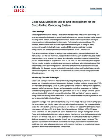
CONFIGURING the SERVERSTEP 4SELECT MEMORYThe standard memory features are: —Clock speed: 2133 MHz—Ranks per DIMM: 1, 2, or 4—Operational voltage: 1.2 V—Registered ECC DDR4 DIMMs (RDIMMs) or load-reduced DIMMs (LRDIMMs)Memory is organized with four memory channels per CPU, with up to three DIMMs perchannel, as shown in Figure 4.Slot 2Slot 3Slot 3Slot 2Slot 1C240 M4 LFF Memory OrganizationSlot 1Figure 4DIMMsA1A2A3E3E2E1Chan AB1B2Chan EB3Chan BC1C2CPU 2Chan CD1D2F2F1G3G2G1H3H2H1Chan FCPU 1C3F3Chan GD3Chan DChan H24 DIMMS1536 GB maximum memory (using 64 GB DIMMs)4 memory channels per CPU,up to 3 DIMMs per channelCisco UCS C240 M4 High-Density Rack Server (Large Form Factor Disk Drive Model)17
CONFIGURING the SERVERSelect DIMMs and Memory MirroringSelect the memory configuration and whether or not you want the memory mirroring option.The available memory DIMMs and mirroring option are listed in Table 6.NOTE: When memory mirroring is enabled, the memory subsystem simultaneouslywrites identical data to two channels. If a memory read from one of the channelsreturns incorrect data due to an uncorrectable memory error, the systemautomatically retrieves the data from the other channel. A transient or soft error inone channel does not affect the mirrored data, and operation continues unless thereis a simultaneous error in exactly the same location on a DIMM and its mirroredDIMM. Memory mirroring reduces the amount of memory available to the operatingsystem by 50% because only one of the two populated channels provides data.Table 6 Available DDR4 DIMMsPID DescriptionVoltageRanks/DIMMUCS-MR-1X648RU-A1, 264GB DDR4-2133-MHz TSV-RDIMM/PC4-17000/octal rank/x41.2 V8UCS-MR-1X322RU-A32GB DDR4-2133-MHz RDIMM/PC4-17000/dual rank/x41.2 V2UCS-ML-1X324RU-A32GB DDR4-2133-MHz LRDIMM/PC4-17000/quad rank/x41.2 V4UCS-MR-1X162RU-A16GB DDR4-2133-MHz RDIMM/PC3-17000/dual rank/x41.2 V2UCS-MR-1X081RU-A8GB DDR4-2133-MHz RDIMM/PC3-17000/single rank/x41.2 V1Product ID (PID)DIMM OptionsMemory Mirroring OptionN01-MMIRRORMemory mirroring optionNotes . . .1. Power capping is not supported when using 64GB TSV-RDIMMS.2. NVIDIA GPUs can support only less than 1 TB of total memory in the server. Do not install more than fourteen64-GB DIMMs when using an NVIDIA GPU card in this server.Approved Configurations(1) 1-CPU configuration without memory mirroring: 18Select from 1 to 12 DIMMs. Refer to Memory Population Rules, page 65, for more detailedinformation.Cisco UCS C240 M4 High-Density Rack Server (Large Form Factor Disk Drive Model)
CONFIGURING the SERVER(2) 1-CPU configuration with memory mirroring: TotalNumberofDIMMsSelect 2, 4, 8, or 12 identical DIMMs. The DIMMs will be placed by the factory as shown in thefollowing table.CPU 1 DIMM Placement in Channels(for identical dual-rank DIMMs for 3DPC or identical quad-rank DIMMs for 2DPC)Blue SlotsBlack SlotsWhite Slots2(A1, B1)——4(A1,B1); (C1,D1)——8(A1,B1); (C1,D1)(A2,B2); (C2,D2)12(A1,B1); (C1,D1)(A2,B2); (C2,D2) (A3,B3); (C3,D3)Select the memory mirroring option (N01-MMIRROR) as shown in Table 6 on page 18.(3) 2-CPU configuration without memory mirroring: Select from 1 to 12 DIMMs per CPU. Refer to Memory Population Rules, page 65, for moredetailed information.(4) 2-CPU configuration with memory mirroring: Numberof DIMMsper CPUSelect 2, 4, 8, or 12 identical DIMMs per CPU. The DIMMs will be placed by the factory asshown in the following table.CPU 1 DIMM Placement in Channels(for identical dual-rank DIMMs for 3DPCor identical quad-rank DIMMs for 2DPC)CPU 2 DIMM Placement in Channels(for identical dual-rank DIMMs for 3DPC oridentical quad-rank DIMMs for 2DPC)Blue SlotsBlack SlotsWhite SlotsBlue SlotsBlack SlotsWhite Slots2(A1, B1)——(E1, ��8 (CPU1)and 2, 2,D2)(A3, B3);(C3, tes . . .1. Not recommended (for performance reasons)Cisco UCS C240 M4 High-Density Rack Server (Large Form Factor Disk Drive Model)19
CONFIGURING the SERVER Select the memory mirroring option (N01-MMIRROR) as shown in Table 6 on page 18.NOTE: System performance is optimized when the DIMM type and quantity are equalfor both CPUs, and when all channels are filled equally across the CPUs in the server.Caveats System speed is dependent on how many DIMMs are populated per channel. See Table 7 fordetails.Table 7 DIMM Memory Speeds with Different CPUs1600-MHz Capable CPU 1866-MHz Capable CPU 2133-MHz Capable CPUDIMM Speed DPC2133 DIMM1LRDIMM(QR)RDIMM (DR,SR)LRDIMM(QR)RDIMM (DR,SR)LRDIMM(QR)RDIMM (DR, 6213321333DPC160016001600160018661866(32 GB RDIMMs and16 GB DIMMs)1600(64 GB TSV RDIMMs,8 GB RDIMMs)Notes . . .1. 2133-MHz DIMMs are the only offered and supported DIMMs for the C220 M4 server 20The C240 M4 server supports four different memory reliability, availability, andserviceability (RAS) modes:—Independent Channel Mode—Mirrored Channel Mode—Lockstep Channel ModeBelow are the system level RAS Mode combination limitations:—Mixing of Independent and Lockstep channel mode is not allowed per platform.—Mixing of Non-Mirrored and Mirrored mode is not allowed per platform.—Mixing of Lockstep and Mirrored mode is not allowed per platform. Do not mix RDIMMs with LRDIMMs Do not mix 64GB DDR4-2133-MHz TSV-RDIMMs with any other DIMMs Single-rank DIMMs can be mixed with dual-rank DIMMs in the same channel Do not mix quad-rank DIMMs with single- or dual-rank DIMMs in the same channelCisco UCS C240 M4 High-Density Rack Server (Large Form Factor Disk Drive Model)
CONFIGURING the SERVER For best performance, observe the following:—DIMMs with different timing parameters can be installed on different slots within thesame channel, but only timings that support the slowest DIMM will be applied to all.As a consequence, faster DIMMs will be operated at timings supported by the slowestDIMM populated.—When one DIMM is used, it must be populated in DIMM slot 1 (farthest away from theCPU) of a given channel.—When single, dual or quad rank DIMMs are populated for 2DPC or 3DPC, alwayspopulate the higher number rank DIMM first (starting from the farthest slot). For a3DPC example, first populate with quad-rank
The UCS C240 M4 LFF server is the newest 2-socket, 2U rack server from Cisco, designed for both performance and expandability over a wide range of storage-intensive infrastructure workloads from big data to collaboration. The enterprise-class UCS C240 M4 SFF server extends the capabilities of Cisco's Unified Computing System