Transcription
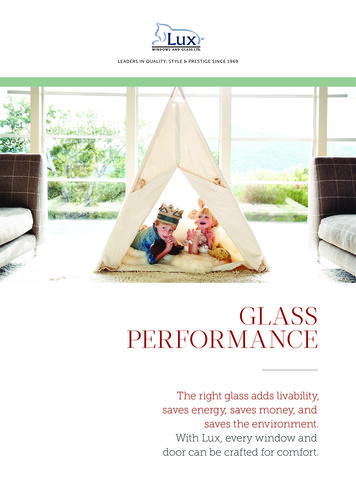
AUSTRALIAN GLASS AND WINDOW ASSOCIATION GUIDE SERIESA GUIDE TO RESIDENTIALINSTALLATIONAN INDUSTRY GUIDE TO THECORRECT INSTALLATION OFWINDOWS AND DOORSVERSION 1AUGUST 2019
CONTENTSFOREWORD3AUSTRALIAN GLASS AND WINDOWASSOCIATION3INDUSTRY GUIDE OBJECTIVE3ACKNOWLEDGEMENT3DISCLAIMER3HOW TO USE THIS GUIDE15MATERIALS KEY15CAVITY VENEER CONSTRUCTION16ALUMINIUM WINDOW INSTALLATION16ALUMINIUM SLIDING DOOR INSTALLATION 18UPVC WINDOW INSTALLATION204UPVC SLIDING DOOR INSTALLATION22THE NATIONAL CONSTRUCTION CODE4TIMBER WINDOW INSTALLATION24INSTALLATION4TIMBER SLIDING DOOR INSTALLATION26IDENTIFICATION OF SITE RATINGS4RESPONSIBILITIESCAVITY MASONRY CONSTRUCTION 28CARE & MAINTENANCE6ALUMINIUM WINDOW INSTALLATIONPRE-INSTALLATION CARE6ALUMINIUM SLIDING DOOR INSTALLATION 30POST-INSTALLATION CARE6UPVC WINDOW INSTALLATION32Door Tracks and Sills6UPVC SLIDING DOOR INSTALLATION34General Soiling7TIMBER WINDOW INSTALLATION36Acid Spills7TIMBER SLIDING DOOR INSTALLATION38Glass7Hardware7Use of Hose8FLASHING28SINGLE SKIN VENEERCONSTRUCTION40ALUMINIUM WINDOW INSTALLATION40As part of its commitment to raising the builtperformance standard of glass, windowsand doors in Australian Glass and WindowAssociation (AGWA) is pleased to provide thisIndustry Guide to the correct installation ofwindows and doors.AUSTRALIAN GLASS AND WINDOWASSOCIATIONAGWA is the peak association representingover 1000 member companies coveringwindow manufacturers, glass manufacturers,glass processors, merchants, glaziers andsuppliers of supporting machinery, servicesand materials. We endorse compliant,sustainable and fit-for-purpose products andprovide services to members that supporttheir efforts to operate successfully.AGWA delivers access to expertise for allmembers and stakeholders in key areasincluding:9ALUMINIUM SLIDING DOOR INSTALLATION 42SILL FLASHING9UPVC WINDOW INSTALLATION44SPECIAL CARE9UPVC SLIDING DOOR INSTALLATION4610TIMBER WINDOW INSTALLATION48 Technical support10TIMBER SLIDING DOOR INSTALLATION50 TrainingAccreditationJAMB FLASHINGHEAD FLASHINGINSTALLATIONCOMMON INSTALLATION PROBLEMSCORRECT INSTALLATION OF FRAMES2FOREWORD12SOLID MASONRY CONSTRUCTION52 12ALUMINIUM WINDOW INSTALLATION52 Communication12ALUMINIUM SLIDING DOOR INSTALLATION 54 Workplace Health and Safety Marketing EventsCONSTRUCTION TYPES14TYPE A: CAVITY VENEER14TYPE B: CAVITY MASONRY14TYPE C: SINGLE SKIN VENEERTYPE D: SOLID MASONRY1414AUSTRALIAN GLASS AND WINDOW ASSOCIATION GUIDE SERIESUPVC WINDOW INSTALLATION56UPVC SLIDING DOOR INSTALLATION58TIMBER WINDOW INSTALLATION60TIMBER SLIDING DOOR INSTALLATION62DRAFT 3DRAFT 3INDUSTRY GUIDE OBJECTIVEThis industry guide to the installation ofwindows and doors sets out to provide thebasic handling and installation instructions forwindows and doors in residential buildings.By providing this resource as an instructionguide it is hoped that windows and doorssupplied to residential buildings remainvaluable and easy to install and maintainduring the construction process.This guide is designed to be used inconjunction with the AGWA IndustryGuide to Fixing.ACKNOWLEDGEMENTThe AGWA gratefully acknowledges thosemember companies whose contribution ofmaterials and continued support to the AGWATechnical Committee and its sub committeeshave made this guide possible.DISCLAIMERThis guide has been developed to providegeneral guidance, awareness and educationto AGWA members, stakeholder groups andconsumers. It should not be viewed as adefinitive guide. While every effort has beenmade to ensure the information is accurate,the AGWA expressly disclaims all and anyliability to any person for anything done inreliance on this publication. No responsibilityis accepted by the AGWA for any mistakes,errors or omissions in this publication.A GUIDE TO RESIDENTIAL INSTALLATION3
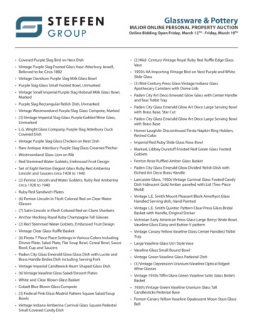
RESPONSIBILITIESTHE NATIONAL CONSTRUCTION CODEThe National Construction Code (NCC) isproduced and maintained by the AustralianBuilding Codes Board (ABCB) on behalf ofthe Australian Government and each Stateand Territory Government.Under the NCC, the Building Code ofAustralia (BCA) is a uniform set of technicalprovisions for the design and constructionof buildings and other structures throughoutAustralia. It allows for variations in climateand geological or geographic conditions.instructions but provide basic and genericguidelines in the absence of such.Approved personal protective equipment(PPE) should be worn at all times whenhandling windows.Special consideration needs to be givento window and door systems designedspecifically for acoustics and energyefficiency. Reference must be madeto the building designer or installer forinstallation details.Under Part 3.0, Section 3.6.0 of Volume 2of the BCA, performance requirements(P2.1 and P2.2.2) are satisfied if windowsare designed and constructed in accordancewith AS 2047. For glazed assemblies notcovered by AS 2047 compliance to AS 1288is required.IDENTIFICATION OF SITE RATINGSUnder Section B and Section F of Volume1 of the BCA, performance requirementsare satisfied if windows are designed andconstructed in accordance with AS 2047.For glazed assemblies not covered byAS 2047, compliance to AS 1288 is required.(a) For housing, the purchaser shouldnominate —AS 2047 Windows and External GlazedDoors in BuildingsAS 1288 Glass in Buildings:Selection and InstallationINSTALLATIONAt all times manufacturer’s installationinstructions will be the predominantprocedure for the installation of proprietarywindows. Installers should ensure thatmanufacturer’s instructions are adopted.The practices outlined in this guide arenot intended to supersede manufacturer’s4RESPONSIBILITIESAUSTRALIAN GLASS AND WINDOW ASSOCIATION GUIDE SERIESExtract from Appendix C AS 2047:2014Nomination of window ratings or designwind pressures for each window and doorassembly should be as follows:(i)the window rating;(ii) the window exposure classification;and(iii) whether the window is a cornerwindow when ordering the windowassemblies.(b) For other residential buildings, thepurchaser should nominate the designwind pressures when ordering thewindow assemblies.(c) For commercial buildings, the purchasershould nominate the design windpressures for the window assemblieswhen ordering the windows.(d) The manufacturer of the windowassemblies should verify the windowassemblies meet the window rating ordesign wind pressures as provided bythe purchaser.DRAFT 3Extract from AS 2047:2014 – Section 88.1 GENERALWindow assemblies for housing shall belabelled in accordance with Clause 8.2.Timber windows for housing and windowassemblies for other than housing shall belabelled in accordance with Clause 8.2, ora certificate in accordance with Clause 8.3shall be provided.Note: Where windows for housing aresupplied as incomplete assemblies, acertificate and a label giving manufacturer’sidentification marks, window rating and waterpenetration resistance should be providedwith the window.that product, it shall be ensured that suchcompliance is capable of being verified.When making a statement of compliance withthis Australian Standard on a variation to atested sample, it shall be ensured that suchcompliance is capable of being verified.Figure 1Performance LabelFigure 2Compliance Certificate8.2 LABELLINGThe label shall be so positioned that thewindow can be identified when viewed in situ.COMPLIANCE CERTIFICATEEach window shall have the followinginformation marked anywhere on thewindow assembly, except on the glazing(the application of rating labels on fixedglazed timber windows is permitted):is a participating member of the AWA Accreditation Program, provides a 6 year Guarantee againstfaulty workmanship and materials (refer to Manufacturer’s Warranty), is committed to the Industry Code ofConduct and has met the requirements of the annual AWA Compliance Audit.The manufacturer certifies that the windows and doors supplied to:Delivery address:(a) The manufacturer’s identification mark.Delivered on:(b) The Serviceability Limit State windpressure.have been manufactured to comply with the Australian Window Standard AS 2047 and Glass StandardAS 1288 including human impact requirements as specified in the order. The windows and doors havebeen manufactured to comply with NCC energy efficiency and bushfire requirements as specified by thepurchaser.(c) The Ultimate Limit State wind pressure.The windows have been manufactured to comply with:Housing(d) The water penetration resistance.Other ConstructionULS PaWPR PaULS PaWPR PaSLSPaN1 400600150C1 6001800150ULSPaN2 400900150C2 8002700200WPRPaN3 6001400150C3 12004000300N4 8002000200C4 16005300450N5 12003000300N6 16004000450SLS Pa8.3 CERTIFICATEA certificate indicating the manufacturer’sidentification, the Serviceability Limit Statewind pressure, the Ultimate Limit State windpressure and the water penetration resistanceshall be provided with window assemblies.The inspectionservices ofthe AWA areaccredited.InspectionAgency Number13739DRAFT 3Note: For corner windows, the nexthighest rating pressure applies.Energy Performance Ratings, AFRC Results: U Value, UwSolar Heat Gain Co efficient, SHGCwRefer to attached scheduleBushfire Rating:BAL 12.5BAL 40BAL 19BAL FZBAL 29Not Required/SpecifiedMethodology:Tested (AS 1530.8.1)Tested (AS 1530.8.2)Prescriptive (AS 3959)Fall Prevention:Windows Restricted to max. 125 mmNot RequiredItem NumbersSigned:Window CompanyWhen making a statement of compliancewith this Australian Standard on a product,packaging or promotional material related toSLS PaFall Prevention ScreensDate:The builder/installer certifies that the windows and doors supplied have been installed correctly inaccordance with the requirements of the National Construction Code and the human impact glass located inthe correct openings.Signed:Builder/InstallerDate:For accreditation details, visit www.awa.org.auDocument No. AWA.CC.A2017A GUIDE TO RESIDENTIAL INSTALLATION5
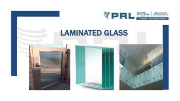
CARE & MAINTENANCEPRE-INSTALLATION CAREFigure 3CARE & MAINTENANCEFigure 5Stacking Windows OnsiteDoor Tracks and SillsIf removal of debris is delayed and scrapingbecomes necessary the finish may bedamaged. Remove cement, mortar andother droppings immediately, using ampleclean water and a sponge or rag to avoidpermanent staining of finished surfaces,as in Figure 6.Windows and doors should be stored ina clean, dry area away from cement, lime,paint, acid etc. and must be protected frombuilding materials and loose debris such aswet plaster, mortar, paint and welding splatter. Store in a dry location, under cover wherepossible, to protect against damage. Carry windows in the vertical positionwith sashes locked. Do not rack frames out of square. Prevent exposure to moisture particularlypooling and ponding. Do not remove any bands (if fitted)from double hung windows until afterinstallation. Do not remove corner bracing (if fitted)until after installation. Do not remove flashing elements (if fitted).Handle and stack frames carefully on site.Stand them upright on their sills (bottom ofthe window as installed), raised off the groundon pieces of timber or bricks. Stand themagainst a flat, vertical surface such as a shedand tie firmly in position, as in Figure 3.General SoilingAcid SpillsAcid used for cleaning brickwork MUSTbe prevented from making contact withpowdercoated or anodised aluminiumwindows and door surfaces. If any acid orsimilar corrosive material does come intocontact with window or door surfaces thoseareas must be washed IMMEDIATELY withlarge quantities of clean water.GlassFigure 4Figure 6Flat Onsite StorageSoilingTo clean glass, simply wipe over the surfacewith a few drops of methylated spirits on adamp cloth and then polish the surface drywith a lint free cloth. Ensure that all cleaningcloths are free of any abrasive substances.Proprietary glass cleaners are notrecommended as some can cause damageto the silver backing on mirrors and theinterlayer in laminated glass. Avoid causingextreme temperature changes as this maylead to thermal fracture of the glass (ie. donot direct hot or cold water onto glass).Do not lean windows against a tree or postas they can be subject to permanent damageuntil installed into the building envelope. Ifthe site is bare, lay frames flat on top of eachother with weight evenly distributed to avoidbuckling and distortion, as shown in Figure 4.HardwarePOST-INSTALLATION CARERegular maintenance is required for allhardware, even stainless steel, as theyare moving parts. In most environmentsmaintenance is recommended every six (6)months and every three (3) months in marineand industrial environments.Door Tracks and SillsDoor tracks and window sills should beprotected from planks, scaffolding andbarrows, as shown in Figure 5.6AUSTRALIAN GLASS AND WINDOW ASSOCIATION GUIDE SERIESDRAFT 3DRAFT 3A GUIDE TO RESIDENTIAL INSTALLATION7
CARE & MAINTENANCEExposed surfaces should first be wipeddown with warm soapy water and a softrag, and then rinsed clean beforeapplying preventative.Figure 7FLASHINGUse of HoseFlashing is essential to achieve properweatherproofing of any wall openings,particularly around windows and doors.It is the builder or installers responsibilityto ensure that windows and doors areinstalled in such a way that water does notpenetrate from the outer skin to the inner skinof the building envelope. The extent of theflashing required depends on local weatherconditions, the exposure of the window to theelements, the type of construction and otherdesign requirements. For further informationplease refer to the relevant sections ofthe NCC.Hangers, pivots and brackets should begiven a light spray of a corrosion preventative(such as CRC Marine 66, Innox or WD40)followed by a light wipe with a dry clothto remove excess.Visible surfaces of hinges should be wipeddown with warm soapy water on a softrag and then rinsed off by wiping with aclean damp rag. Application of a thin filmof light machine oil or one of the corrosionpreventative sprays mentioned above willhelp to maintain the original lustre of themetal finish.Must be provided with weepholes tolet the water out. Maximum weepholespacing is 1200 mm from centres. In cavity construction: Must be smooth and not sag intocavity where it could collect water. Must not extend more than half thewidth of the outside brick skin.SPECIAL CARESpecial care is required on windows withundersill drainage used in a non cavitysituation such as single skin block work.There are three types of flashing: Sill, Jamband Head. Flashing must be installed frombottom to top, in the following order, so thateach layer overlaps the one below:Where a subsill is used stop ends must befitted and sealed.Be careful not to get these compounds ontimberwork or anodised surfaces as they maycause staining.1.Sill flashingFigure 82.Jamb Flashing3.Head FlashingDrop bolts should be sprayed with a lubricantsuch as those mentioned above at the slidingpin inside the bolt and to the lock cylinder.A tube attached to the nozzle will help toconcentrate the spray where you wantit to go.The sarking above the window overlaps thehead flashing. Overlap is vital to ensure that,at each transition, water is directed onto theelement below.If using a hose or similar apparatus to cleanwindows and/or doors ensure the hosenozzle/jet fitting is set to a fine spray asshown in the diagram. At NO time should awindow or door be hit with a full force of ahose, nozzle/jet setting as this may damagewindow seals and adversely affect airinfiltration and water penetration performance.Figure 7.AUSTRALIAN GLASS AND WINDOW ASSOCIATION GUIDE SERIESWindow Sill FlashingDrainage must be provided below the windowor door, so that any water captured has theability to escape to the outside of the wall.Use of Hose8 SILL FLASHINGSill flashing must be installed to prevent waterwetting the inner skin and entering the cavityunder the window or door. Sill flashing alsocollects run off from the jamb flashing anddirects it outside the building envelope.DRAFT 3 Must project a minimum of 150 mm bothsides past the opening. Must be made of approved materials andcomply with AS/NZS 2904.DRAFT 3150mmA GUIDE TO RESIDENTIAL INSTALLATION9
FLASHINGFLASHINGJAMB FLASHINGHEAD FLASHINGJamb flashing is required in high windlocations to ensure that water which entersbetween the jamb and the outer skin isdrained into the sill flashing.Head flashing must be installed to stop waterwetting the inner skin by bridging across thewindow or door head. Where jamb flashing overlaps sill flashing,the overlap should extend the full depthof the sill flashing. Must extend the full depth of the sillflashing and project vertically a minimumof 150 mm above the opening. Must be installed above any wallpenetrations not specifically designedto stop water reaching the inner skin(for example, exhaust fans andventilation ducts). Must project horizontally a minimum of150 mm both sides past the opening. Must project horizontally a minimum of150 mm both sides past the opening. Must project vertically a minimum of150 mm above the opening. Must be made of approved materials andcomply with AS/NZS 2904. Must be made of approved materialsand comply with AS/NZS 2904.Figure 9Figure 10Jamb FlashingMust be provided with weepholes tolet the water out. Maximum weepholespacing is 1200 mm from centres. In cavity masonry construction, headflashing must be built into the inner skina minimum of 30 mm.Head Flashingm150mm150m 10AUSTRALIAN GLASS AND WINDOW ASSOCIATION GUIDE SERIESDRAFT 3DRAFT 3A GUIDE TO RESIDENTIAL INSTALLATION11
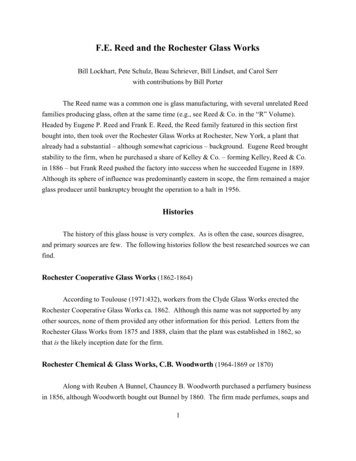
INSTALLATIONINSTALLATIONTo ensure the satisfactory long termperformance of sliding doors, the sillshould be fully supported. Where thesill projects during construction the sillshould be fully supported.COMMON INSTALLATION PROBLEMSInstallation problems are the prime causeof leaks in window assemblies. Contributingfactors include omission or incorrect fittingof flashing, smothered or missing weepholes,or the loss of continuity in the water barrier.The severity of wind exposure is themost important factor in the specificationand installation of windows and doors.Components and installation practicesacceptable in sheltered situations mayquickly fail when exposed to the full forceof the wind and rain.4.Keep sashes closed whilst installingframes.5.Secure frames with a fixing of a gaugeand spacing appropriate for the windload.In brick veneer constructions, aluminiumframes should be secured by nailing orscrewing through reveal into stud work.Fit flashing to window surround asrequired.2.Measure the frame opening to ensurethat there is sufficient room for theproduct and additional packing.Width O/A reveal size adequate clearanceClearance dimensions vary betweenmanufacturer’s products. For adequateclearance, refer to instructions.3.Frame must be packed plumb, squareand not twisted between the openings.Ensure the sill is fully supported. Failureto do so may result in sill roll on slidingwindows.AUSTRALIAN GLASS AND WINDOW ASSOCIATION GUIDE SERIESSpirit Level:Ensure jambs areplumb and straightbefore fixingSTRUCTUAL MEMBERSWedgeat thesepointsFJAMBF6.Sill/head bricks should be at least 10 mmclear of window frame to allow settlementin brick veneer construction.7.Do not permit weight of eaves or archbars to bear on any window or doorframe. Windows and doors are notload bearing.Fix via building lugs,nails or shim at equallyspaced arrow points.8.Sills on all windows and doors must bestraight and level and should be packedand secured.12CheckMeasurementsBuilding in Fixings or Lugs equally spacedIn cavity brick construction usegalvanized building lugs located at450 mm maximum centres.Stud OpeningHeight O/A reveal size adequate clearanceInstallation SummaryTimber windows should be securedby back nailing through stud, not faceof frame stud. If it is not possible tobacknail, wedges should be installedbetween the window and the buildingframe to prevent opening of the framejoints when nailing is carried out.CORRECT INSTALLATION OF FRAMES1.Figure 11DRAFT 3SILLDo not stand on the windows or doors,or use them as a support for scaffolding,or slide material through the frame. Itis important to prevent any damage towindows and doors during construction.DRAFT 3FSpirit Level:Ensure sill is levelby packing9.Ensure packer or supportunder structual membersRemove cement mortar and plasterdroppings from windows immediately,taking care to avoid scratching glass and,or frames, as permanent damage canresult. Immediately wash off with waterbefore material sets.A GUIDE TO RESIDENTIAL INSTALLATION13
CONSTRUCTION TYPESThere are many different forms ofconstruction in use throughout Australia.Most commonly, houses are built usingeither timber of steel frames with a varietyof external cladding finishes, brick veneeror double brick construction. Larger buildingsuch as residential apartment blocksand commercial buildings are typicallyconstructed using either one or a combinationof construction types such as filled concreteblockwork, tilt slab or slab on pier methods.Though there a wide variety of constructiontechniques, these can broadly be categorisedinto four types:VeneerMasonryCavityABSingle SkinCDTYPE A:CAVITY VENEER CONSTRUCTIONThe most common form of type Aconstruction is brick veneer and is popularfor houses and small buildings. The internalframe, usually timber or steel is built with asingle outer skin of bricks that are tied tothe frame for structural stability. Between theinternal frame and outer brickwork is a cavityof about 40- 50 mm which acts as a naturalbarrier to water ingress.TYPE B:CAVITY MASONRY CONSTRUCTIONDouble-skin masonry, typically double brick,is a more traditional style of constructionstill favoured in hot, dry climates due to its14AUSTRALIAN GLASS AND WINDOW ASSOCIATION GUIDE SERIESHOW TO USE THIS GUIDEsuperior thermal insulation characteristics.It features an inner and outer skin of bricksseparated by a cavity, usually 50 mm, withthe inner and outer skins tied together forstructural stabilityTYPE C:SINGLE SKIN VENEER CONSTRUCTIONClad construction is a simple, cost effectiveconstruction technique featuring either atimber or steel frame over which an externalcladding is fixed directly. There are manydifferent types of cladding that are popularincluding masonry fibre sheeting, shiplap,timber, PVC and composites. Claddingsystems do not typically have a cavity in thewall, and require a higher degree of diligenceand workmanship to achieve an adequateseal.TYPE D:SOLID MASONRY CONSTRUCTIONSolid masonry walls are sometimes seenin residential constructions, though arecommon in commercial applications.Blockwork is a form of masonry constructionpopular in low-rise constructions. It is usuallyconstructed using hollow concrete blocks.These blocks can be left hollow, however toimprove structural stability, the hollow coreis often reinforced with steel and filled withconcrete. Another form of solid masonry wallconstruction is Tilt Slab which has becomeprevalent in the last two decades. Concretewall sections are pre-fabricated in a factory,transported to site and assembled.Generally the individual concrete panelsare tied to a steel frame however they maybe free-standing.DRAFT 3This guide is divided into four sections basedon the four main construciton types:Cavity veneer constructionCavity masonry constructionSingle skin veneer constructionSolid masonry constructionThe installation diagrams are then collated byframe material type as follows:Construction type Aluminium Window Installation Aluminium Sliding Door gglass/glazingimpervious filmpacker uPVC Window Installationmasonry/concrete uPVC Sliding Door Installationmasonry plug Timber Window Installation Timber Sliding Door InstallationThis guide is designed to be used inconjunction with the AGWA Industry Guide toFixing to ensure that windows and doors arefixed with an appropriate gauge and spacingfor the site specific wind loads.mortarsarkingmetal (lintel, steel reinforcement)sealant/caulkstud frametimber (frame, reveal, architrave)uPVCDRAFT 3A GUIDE TO RESIDENTIAL INSTALLATION15
CAVITY VENEER CONSTRUCTIONCAVITY VENEER CONSTRUCTIONALUMINIUM WINDOW INSTALLATIONALUMINIUM WINDOW INSTALLATIONHead1.2.HEAD FLASHINGEXTERNALBRICKWORK3.STUD FRAMEWEEPHOLES4.5.6.Sarking overlaps head flashing.Head flashing (mandatory) goes into,or one course above, lintel. Head flashinggoes over jamb flashing.Maximum spacing for weepholes inbrickwork is 1200 mm (from centres).Sealant (exterior).Window head fitted to timber reveal.Fix reveal to lintel with a fixing of a gaugeand spacing appropriate for the wind load.1LINTELBRICKVENEERINTERNALWALL LINING2ARCHITRAVE510mm clearance346JambSARKING1.2.JAMB FLASHING3.4.5.WEEPHOLESSILL FLASHING2.IMPORTANT3.Ensure building loads do not bear on window.4.5.6.Separate the window sill and outside brickskin with an isolating material to preventpossible reaction between brick/mortar andthe aluminium framing. Contact can lead toextensive corrosion.7.8.Sill must be level side to side and frontto back, and fully supported at all times.AUSTRALIAN GLASS AND WINDOW ASSOCIATION GUIDE SERIESINTERNAL WALL LININGDRAFT 3ARCHITRAVE1STUDFRAME2534BRICK VENEERSill1.16Packer.Fix reveal to stud frame with a fixing ofa gauge and spacing appropriate for thewind load.Jamb flashing attached to the windowor wall framing.Sealant (exterior).Jamb flashing overlaps sarking.Mandatory sill clearance of 10 mm.Shown with optional sill flap.Sill flashing (mandatory) sandwichedbetween fixing fin and rereveal.Fix reveal to stud frame with a fixing ofa gauge and spacing appropriate forthe wind load.Pack sill level where required.Sarking.Preferred flashing position(one brick course down).Alternate flashing position.Weepholes in brickwork must be aboveflashing. Max spacing is 1200 mm(from centres).DRAFT 312310mm RAVEINTERNALWALLLINING56A GUIDE TO RESIDENTIAL INSTALLATION17
CAVITY VENEER CONSTRUCTIONCAVITY VENEER CONSTRUCTIONALUMINIUM SLIDING DOOR INSTALLATIONALUMINIUM SLIDING DOOR INSTALLATIONHeadHEAD FLASHINGEXTERNALBRICKWORKSTUD FRAMEWEEPHOLESSARKINGSarking overlaps head flashing.2.Head flashing (mandatory) goes into, orone course above, lintel. Head flashinggoes over jamb flashing.3.Maximum spacing for weepholes inbrickwork is 1200 mm (from centres).4.Sealant (exterior).5.Door head fitted to timber reveal.6.Fix reveal to stud lintel with a fixing ofa gauge and spacing appropriate forthe wind load.LINTELBRICKVENEERSLAB1.Packer.2.Fix reveal to stud frame with a fixing ofa gauge and spacing appropriate forthe wind load.3.INTERNALWALL LINING23ARCHITRAVE510mm clearance46INTERNAL WALL LININGJambJAMB FLASHINGWEEPHOLES1.1ARCHITRAVE12STUDFRAME35Jamb flashing attached to the dooror wall framing4.Sealant (exterior).5.Jamb flashing overlaps sarking.4BRICK VENEERSillSILL FLASHINGIMPORTANTEnsure building loads do not bear on door.Separate the Sill and outside brick skin withan isolating material to prevent possiblereaction between brick/mortar and thealuminium framing. Contact can lead toextensive corrosion.1.Angle trim sealed to structure and doorsill (with masonry plug where required).2.Pack sill to level where required.3.Sill flashing tray (mandatory) turned upand sealed at each end.4.Weepholes must be above sill flashing.Maximum spacing for weepholes inbrickwork is 1200 mm (from centres).12SLAB43Sill must be level side to side and frontto back, and fully supported at all times.18AUSTRALIAN GLASS AND WINDOW ASSOCIATION GUIDE SERIESDRAFT 3DRAFT 3A GUIDE TO RESIDENTIAL INSTALLATION19
CAVITY VENEER CONSTRUCTIONCAVITY VENEER CONSTRUCTIONUPVC WINDOW INSTALLATIONUPVC WINDOW INSTALLATIONHeadHEAD FLASHINGEXTERNALBRICKWORK1.Sarking overlaps head flashing.2.Head flashing (mandatory) goes into,or one course above, lintel. Head flashinggoes over jamb flashing.3.Maximum spacing for weepholes inbrickwork is 1200 mm (from centres).STUD FRAMEWEEPHOLES4.Sealant (exterior).5.Window fitted to timber reveal.6.Fix reveal to lintel with a fixing of a gaugeand spacing appropriate for the wind load.1LINTELBRICKVENEERINTERNALWALL LININGARCHITRAVE25310mm clearance46JambSARKINGJAMB FLASHINGWEEPHOLESSILL FLASHING1.Packer.2.Fix reveal to lintel with a fixing of a gaugeand spacing appropriate for the wind load.3.Sealant (exterior).4.Jamb flashing attached to the windowor wall framing.5.Jamb flashing overlaps sarking.INTERNAL WALL LININGSTUDFRAMEEnsure building loads do not bear on window.Sill must be level side to side and frontto back, and fully supported at all times.254SillIMPORTANT13BRICK VENEER1.Mandatory sill clearance is 10 mm.Shown here with optional sill flap.2.Sill flashing (mandatory) sandwichedbetween window fixing fin and reveal.3.Fix reveal to lintel with a fixing of a gaugeand spacing appropriate for the wind load.4.Pack sill to level where required.5.Sarking.6.Preferred flashing position.7.Alternate flashing position.8.Maximum spacing for weepholes inbrickwork is 1200 mm (from centres).Keep weepholes above flashing.1310mm NALWALLLINING5620AUSTRALIAN GLASS AND WINDOW ASSOCIATION GUIDE SERIESDRAFT 3DRAFT 3A GUIDE TO RESIDENTIAL INSTALLATION21
CAVITY VENEER CONSTRUCTIONCAVITY VENEER CONSTRUCTIONUPVC SLIDING DOOR INSTALLATIONUPVC SLIDING DOOR INSTALLATIONHeadHEAD FLASHINGEXTERNALBRICKWORKSTUD FRAMEWEEPHOLESSARKINGSLABIMPORTANTEnsure building loads do not bear on door.Sill must be level side to side and frontto back, and fully supported at all times.AUSTRALIAN GLASS AND WINDOW ASSOCIATION GUIDE SERIES2.Head flashing (mandatory) goesinto, or one course above, lintel.Head flashing goes overjamb flashing.3.Maximum spacing for weepholes inbrickwork is 1200 mm (from centres).4.Sealant (exterior).5.Door head fitted to timber reveal.6.Fix reveal to lintel with a fixing of a gaugeand spacing appropriate for the wind load.1.Packer.2.Fix reveal to studwork with a fixing of agauge and spacing appropriate for thewind load.3.Jamb flashing attached
Proprietary glass cleaners are not recommended as some can cause damage to the silver backing on mirrors and the interlayer in laminated glass. Avoid causing extreme temperature changes as this may lead to thermal fracture of the glass (ie. do not direct hot or cold water onto glass). Hardware Regular maintenance is required for all