Transcription
LETTER OF TRANSMITTALPavle Djuricanin, Eric Bakke, Peter ChenUBC Engineering Physics Project Lab6224 Agricultural RoadVancouver, BC. V6T 1Z1April 2nd, 2007Jon Nakane, Lab ManagerUBC Engineering Physics Project Lab6224 Agricultural RoadVancouver, BC. V6T 1Z1604.822.2110Dear Dr. Young and Dr. Nakane:We are writing to you with the project report titled Frequency LockingSystem for Grating-Stabilized Diode Lasers enclosed. The purpose of writing thisreport is to analyze the project in detail in terms of designing, construction, andtesting as part of the APSC 459 Project Report. This project officially started onJanuary 7th and was completed on April 1st, 2007 in the UBC Quantum DegenerateGas Laboratory. The sponsors for this project are Dr. David Jones, and Dr. KirkMadison. A few other personnel including research associate Dr. Bruce Klappaufand graduate student Jannelle Van Dongen assisted in the completion of thisproject. The report focuses on the design and construction of the grating-stabilizeddiode laser and includes details on testing the complete frequency locking system.The visual results under the results discussion section display a very intuitiveexplanation of the how each debugging and testing method was formed. This issubmitted as a final copy of the report. Please let us know if you have anyconcerns.Sincerely,Eric Bakke, Peter Chen, and Pavle DjuricaninAPSC 459 Students, Project 0717Encl. Project Report
FREQUENCY LOCKING SYSTEM FOR GRATING-STABILIZED DIODELASERS REPORTEric BakkePeter ChenPavle DjuricaninProject Sponsors:Dr. David JonesDr. Kirk MadisonApplied Science 459Engineering PhysicsThe University of British ColumbiaApril 2nd, 2007Project Number 0717
Executive SummaryThe aim of this project is to design a system to lock the frequency of a Grating-StabilizedDiode Laser (GSDL) to a master laser at a constant frequency difference. The significanceof such a device is applied in laser cooling and manipulating of ultra-cold atoms at thequantum level. Laser cooling requires multiple lasers at specific frequency differencesapart from an atomic transition of the gas being cooled. Locking laser frequency directlyfrom absorption peaks of Rubidium is complicated and costly. The purpose of this projectis to design an alternative method of locking the frequency of a GSDL by means ofcomparing its output frequency to that of an existing locked laser. Thus using the results ofthis experiment one could lock any number of GSDLs to frequencies ranging from theexact frequency of the reference laser to 2 GHZ offset on either side for fractions of thecost of using current methods. Larger offsets are presumed possible with faster respondingphoto-diodes as this is the limiting component in our project.Our group has built an enclosed, portable, slave GSDL for frequency locking with aknown external cavity diode laser setup; the Littman configuration. This configurationsends the 1st order beam from a diffraction grating back into the laser as a source offeedback and frequency tuning. Light from a Master Laser, which is locked to an atomictransition of Rubidium, will interfere with light from the Slave GSDL to create a beatnotewith a frequency proportional to the frequency difference between the two lasers. Thisbeat-note frequency is compared with a stable reference signal to generate an error signal.The error signal output is fed to a PI Servo that changes the piezoelectric driver input. Thispiezoelectric driver input changes the angle of mirror in the external cavity of the slaveGSDL, changing the output frequency of the slave GSDL, so that the frequency differencebetween the two lasers stays constant. The production and design of the sensor, digitalcomparator and PI Servo are not part of this project and are designed by other personnel inthe optics laboratory.The key testing methods are to monitor the absorption spectrum of Rubidium and the beatnote signal using a spectral analyzer and analog oscilloscope. Monitoring the Rubidiumabsorption spectrum provides an intuitive visual output of mode-hop free regions. Thelaser we have built is able to lock on to the master laser frequency for several minutes at atime however the slave laser did not maintain the lock for the a prolonged amount of timeas initially desired.This project is sponsored by professors Dr. Jones and Dr. Madison of the optics laboratoryat the University of British Columbia. And all experiments were performed in theQuantum Degenerate Gases Laboratory.
List of FiguresFigure 1:One-dimensional simplified schematic of photon-matter interaction.Figure 2:A similar setup to the current use of Rubidium vapor atomic transition frequencyto stabilize diode laser frequency [2]Figure 3:Schematic Diagram of the Overall ProjectFigure 4:Rubidium absorption spectrum displaying the four absorption peaks (orminimums) over a range of frequency. [9]Figure 5:The Littrow Configuration: 1) Laser Diode Output 2) Amplification Beam 3)Diffraction Beam 4) GSDL OutputFigure 6:The Littman Configuration: 1) Laser Diode Output 2) 0th Order Diffraction Beam3) 1st Order Diffraction Beam 4) Diffracted Amplification BeamFigure 7:The block diagram of the negative feedback control system representing thecomplete frequency locking system.Figure 8:Simple internal schematics of the enclosed diode laser used initially to do testingwith bandwidth optimization.Figure 9:The laser setup with the experimental setup of the external cavity. The externalcavity is the path between the laser diode to the diffraction grating to the mirrorproviding the feedback.Figure 10:The complete setup of experimental setup with extended path to spectroscopepickup. The beam splitter between the isolator and the mirrors splits the beamtowards Rubidium absorption segment as shown in Figure 11.Figure 10 (b):Peak Wavelength vs Knob Turn NumberFigure 11:The setup after the beam splitter which is sent through a glass slide to separate thebeam to Rubidium cell and feedback to a photo-detector (or power meter).Figure 12:A photo displaying the florescence of Rubidium as seen through the infraredviewer to determine whether the resonance frequency is obtained.Figure 13:Example of several absorption scan data obtained from the Tektronix oscilloscope.The plot displays the Rubidium-87 re-pump peak needed for frequency locktesting.Figure 14:The red line illustrates the bandwidth of the light be injected into the diode by theback reflection mirror. The blue delta functions indicate frequencies that satisfythe boundary conditions imposed by the external cavity of the GSLD.
Figure 15:The setup of the mirror mount placed on a linear stage to slide the mirror along theparallel direction of the mirror surface to allow the beam to hit different positionson the mirror.Figure 16:Bandwidth of mod-hop free sweep vs spot placement graphical data.Figure 17:Initial design setup of the grating stabilize diode laser. The left is the originalproposal. The right displays changes made to the base orientation in order for thebeam to output normal to the left-side plate.Figure 18:The top view of the final constructed grating stabilized diode laser with labeledcomponents.Figure 19:A schematic view of the final design of the grating stabilized diode laser.Figure 20:An oscilloscope trace and photo displaying the ramped current of the PTZ (pink)and the resonance beat-note signal (blue) and the Rubidium absorption spectrum ofan Rubidium-87 re-pump peak.Figure 21:A similar oscilloscope trace and photo displaying the ramped current of the PTZ(pink) and the resonance beat-note signal (blue) and the Rubidium absorptionspectrum of an Rubidium-87 re-pumpFigure 22:(a) A signal of the beat-note (divided down) with low resolution (b) The samebeat-note with a higher resolution displaying an almost perfect sine wave. (c) Thesame beat-note with high resolution (though not very clear).Table 1: Electronic Equipment ListingTable 2: Tabletop Optical ComponentsTable 3: Developed ComponentsLIST OF ABBREVIATIONSAOMAcousto-Optic Modulator
ECDLFLSFVCGSDLPTZQDGExternal Cavity Diode LaserFrequency Locking SystemFrequency to Voltage ConverterGrating Stabilized Diode LaserPiezoelectric TransducersQuantum Degenerate Gasses
TABLE OF CONTENTSTable of ContentsEXECUTIVE SUMMARY . 3LIST OF FIGURES . 4TABLE OF CONTENTS . 71.0 INTRODUCTION . 11.1Background .21.1.1Laser Cooling .21.1.2Current Rubidium Gas Transition Locking System.31.1.3The Frequency Locking System .41.2Project Objective.61.3Scope and Limitations .81.4Organizations .82.0 DISCUSSION . 82.12.22.32.4Theory .92.1.1Rubidium Electron Transition.92.1.2Grating Stabilized Diode Laser.102.1.3The Negative Feedback Control System .11Methods and Testing Protocols .132.2.1Experiment Equipments and Parts.132.2.2Experimental Internal Setup of the Laser.142.2.3Experimental Setup of the External Cavity .152.2.4Bandwidth Optimization.15Design Proposal .222.3.1Design Criteria and Requirements.222.3.2Initial Design Proposal.232.3.3Pre-Construction Changes to Design.23Final Design .242.4.1Finalized Laser .252.4.2Post-Construction Changes to Design .252.5Data.272.6Results .28
TABLE OF CONTENTS2.6.1Discussion of Project Data.282.7 Laser Locking Results .303.0 CONCLUSION .324.0 RECOMMENDATIONS .334.1 The Present Laser System .334.1.1 Anti-Reflection Coated Laser Diode .334.1.2 Acoustic Vibration Isolation .334.2 The Frequency Locking System .344.2.1Beatnote Frequency Division.345.0 APPENDICES .356.0 REFERENCES.35PROJECT EVALUATION .39
1 INTRODUCTION1.0INTRODUCTIONLaser cooling is a recently developed technique used to slow down atoms andsubsequently cool down their temperature. This technique can be exploited to study andanalyze the atom at a quantum level by manipulating ultra-cold atoms.Laser cooling of atoms, however, has proven to be a difficult task as it requires multiplefrequency-variable lasers locked at very specific frequencies relative to one another. It isnot sufficient to simply tune two lasers to the appropriate wavelengths as the lasers willnot maintain that output frequency. Lasers have a tendency to drift , or in more preciseterms, slowly shift their outputted wavelength. The current frequency locking systememployed in the Quantum Degenerate Gas (QDG) Laboratory requires expensivecomponents and a complicated assembly procedure. Converting such a system to enablelocking through electronic means rather than optical would be both cost efficient, andmore flexible than the current system. The main component of such a system requires theuse of an External Cavity Diode Laser (ECDL). Single mode laser diodes commerciallyintroduced in the last decade are acceptable in performing high-resolution spectroscopy onatoms and molecules. However the tunability of these diodes is not sufficient forapplications in laser cooling where the diode laser needs to lase at 780 nm. [3] Theperformance of the frequency tuning on these diode lasers can, however, be improved byintroducing an external cavity that provides optical feedback to generate sensitive tuning.The Frequency Locking System (FLS) uses the superposition of optical signals from theECDL and a master laser to generate a beat-note with a frequency equal to the differenceof the respective frequencies of the lasers. With this beat-note divided down to a suitablefrequency, it is compared with a synthesized signal to produce an error that is used to lockthe slave laser at a constant frequency difference from the master laser.The project is aimed to design and construct an ECDL that tunes its own frequencyaccording to a frequency from another laser using a diffraction grating; a FrequencyLocking System for Grating Stabilized Diode Lasers. The approach in designing thisfrequency-tunable laser is by constructing an external cavity consisting of a diffractiongrating and an angularly adjustable mirror to send the diffracted 1st order beam back intothe laser for feedback.1
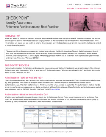
1 INTRODUCTION1.1BackgroundAlthough the focus of this report and project is centered on the design and construction ofa GSDL and FLS, background on laser cooling is important to recognize the significanceof the FLS and its purpose. This section briefly explains what laser cooling is and how itworks as well as the existing technique employed to lock a frequency of a laser in theQDG Laboratory at the University of British Columbia.1.1.1Laser CoolingD. J. Wineland first demonstrated laser cooling in 1978. It is essentially a method thatutilizes lasers to freeze atoms in a contained space. The basic concept of laser cooling is totransfer energy and momentum from the photon to the atom in order to slow it down. Thetemperature of a collection of gas molecules is related to their kinetic energy (i.e. theiraverage velocity). By slowing down the atoms in a localized region, it is possible torapidly cool down the temperature of the gas to a fraction of a millikelvin. The followingdiagram will aid in the discussion.Figure 1: One-dimensional simplified schematic of photon-matter interaction.To simplify the discussion of laser cooling, only the one-dimensional case will be focusedupon. When a photon, propagating at a resonant frequency, strikes an atom, it is absorbedand an electron within the atom makes a transition to a higher state given by the equation:The atom then spontaneously emits this energy in a random direction.However, if the atom is moving in the opposite direction of incoming light, it will see ahigher frequency due to the Doppler shift effect. Therefore, by adjusting the frequency ( p)of the incoming photon slightly below resonance, the moving atom will see a resonant2
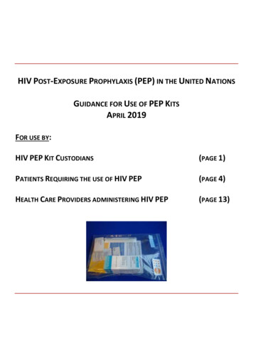
1 INTRODUCTIONfrequency photon. The atom will absorb this photon, again causing a transition jump of theelectron and then later a spontaneous emission. Looking closely at the energy components,the energy of the absorbed photon is:The energy released by the atom upon spontaneous emission is given by (1). Since theresonant frequency 0 is larger than the photon frequency p, the atom will lose moreenergy than it receives, causing it to slow down.When the atom travels in the opposite direction, it sees the photon frequency below p andis therefore unaffected by its presence. In order to stop an atom traveling to the right, alight source is set up to the right of the atom with the incoming light pointed to the left.Thus the use of the two lasers aimed in opposite directions will slow down the atomalmost to a complete stop.Expanding the design to a three dimensional environment requires three coupled lasers inthe three respective coordinates of space. The atoms cannot be completely stopped sincethere is recoil when they spontaneously emit a photon in a random direction.1.1.2Current Rubidium Gas Transition Locking SystemCurrent FLSs are very similar to the one shown in Figure 2. The light output from the laseris split into two parts, one part is used as the output light and the other is used to performthe locking. The laser output that is used to perform the locking of the frequency to aparticular atomic transition is back reflected from the Rubidium cell. This light is then sentinto the photodiode in order to convert the optical signal into an electronic one that can beused by the Lock Box. The lock-in mechanism is usually a PID controller which adjustscertain actuators on the laser (usually current and piezo) to lock the lasers frequency. Withthe laser locked to a specific Rubidium transition, the output light frequency is shifted byan Acousto-Optic Modulator (AOM) to the Doppler shift frequency. This is the light usedto accomplish laser cooling. The drawback of this system is that AOMs only have alimited range in which they can shift the output frequency. This poses an overall limit onthe frequency range that a laser s output light can be locked.3
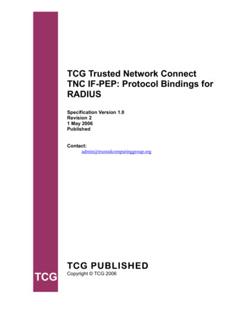
1 INTRODUCTIONFigure 2: A similar setup to the current use of Rubidium vapor atomic transition frequency tostabilize diode laser frequency [2]With the development of high-speed photodiode detectors that have a capability ofdetecting signals up to 10 GHz, a more flexible FLS than the one currently used could beconstructed. This new FLS would also have the capability of locking to frequencies muchfurther apart from atomic transitions. The description of this FLS works, along withtopography is provided in the next section.1.1.3The Frequency Locking SystemFrom Figure 3, the master laser is locked to a certain Rubidium atomic transition andoutputs light, at a constant frequency, onto a beam splitter. The slave laser also directs abeam towards the beam splitter by the use of a mirror. The two signals interfere at thephoto-detector resulting in a beat-note with a frequency proportional to the frequencydifference between the two lasers. The detector used in the system can detect frequenciesup to 2 GHz.4
1 INTRODUCTIONFigure 3: Schematic Diagram of the Overall ProjectThe signal from the photo-detector is compared to a reference signal generated by a DirectDigital Synthesizer (DDS) in the Frequency to Voltage Converter (FVC). The FVC has afrequency limit of 150 MHz and it generates an error signal that is proportional to thephase of the frequency difference of the two input signals. The output of the FVC is sentto the PI Servo. The PI servo has 3 adjustable gains, one corresponding the high frequencycontrol signal which is fed to the current controller. The other two gains are theproportional and integral, and they control the piezo driver. This thereby provides thefeedback portion of the control system. Now that the actuation signals for the current andpiezo are carried into their respective controllers, the current and piezo will shiftaccordingly in order to keep the beat-note frequency constant, and thereby lock the slavelaser.The main advantage of this FLS is that once a master has been locked to a Rubidiumtransition, the slave laser can be locked to any frequency within the limits of producing abeat-note which can be detected by the photodiode. Thus using an avalanche photodetector with an upper limit of 10 GHz and appropriate frequency division to meet thestandards to the FVC frequency limit, the slave laser can lock to anywhere within the 10GHz supported by the detector.5
1 INTRODUCTION1.21.Project ObjectiveDesign modification of GSLDThe current design utilized by Dr. Jones and Dr. Madison are intended for morerugged, all around purposes and as such contain extra components that complicateand interfere with the purposes of this project. A simpler more dependable design isrequired that satisfies the purposes of only this project.To address this we intended to submit a final design for approval by Dr. Madisonand Dr. Jones by January 20, 2007.2.Construction of GSLDa. Laser Temperature StabilizationTo extend the life and optical strength of the diode laser, the diode must bemaintained at a stable, low temperature of approximately 5 C. Using a TEC coolersystem, this portion of the design consisted of a thermistor, thermal paste, a TECcooler and an off the shelf electronic control unit (TEC 2000 2A / 12 W).b. Controlled Angle of Diffraction GratingIn order to change the frequency of the laser, the angle of the back reflecting mirrormust be finely tunable. To accomplish this the angle of the mirror is controlledelectronically via a piezo electronic transducer. The piezo unit is placed behind oneend of the mirror and a steel pivot is placed behind the other end. This allows themirror angle to be adequately controlled on the magnitude of 1/1000 of a degree.The controlling of the PTZ is done by the circuitry provided by the electronics shop.The voltage levels applied by the PTZ driver vary between 0V and 150V.c. Operational Laser DiodeThe laser diode did not require to be redesigned but was rather incorporated into theGSLD design. Dr. Jones and Dr. Madison delivered the required diode for theGSLD.We had intended to have a completed GSLD ready for testing by February 16, 2007.3.Creation of Beatnote and Combination of System Components6
1 INTRODUCTIONThe outputs of the master and slave lasers are superimposed to produce a beat-note.This beat-note is then delivered to a high-speed photo-diode. The output of thisphoto-diode is then passed on to the error producing Frequency-to-Voltageconverter. The Frequency-to-Voltage converter reads in the frequency of thebeatnote, compares it to a reference frequency and then outputs an error that isconnected to a PI locking electronics system. The output of the PI locking system isthen amplified and used to control the piezo and laser current.4.Operational Frequency Locking SystemOnce the beat-note is produced and an error signal obtained, the final and mainobjective of this project is to obtain a stable null error by utilizing the fast and slowoutputs of the PI lock box to control the frequency of the GSLD. Proper values forthe overall gain, proportional gain, integral gain and fast and slow attenuation areexperimentally determined to maximize the stability of the GSDLs frequency.7
1 INTRODUCTION1.3Scope and LimitationsThe scope of this report is encompassed in the analysis of the design specifications of theFrequency Locking System as well as the results of testing procedures used during thedesign and construction of the ECDL. Also, details from the testing of the FLS areidentified in this document. Specifications regarding the design and schematics of externalelectronics including photo-detector, frequency dividers, digital comparators, and the PIservo control, however, will be briefed but not closely examined as the core focus of theproject lies in the design and construction of the grating stabilized diode laser. Theomission of such details should not produce a large impact on this report, as theelectronics provided had no major changes and issues with the progress of the project.1.4OrganizationThis report is composed of sections describing the theory of frequency locking to illustratethe different approaches in designing a frequency tunable laser; Littman and Littrowconfigurations. The discussion section will also include an analysis of the initial design,final design, temporary tabletop setup, and changes made to the designs. A generaloverview of the complete negative feedback system of the FLS is addressed in thediscussion section. Finally, visual results and graphical data are analyzed in the resultssection as well as an evaluation of the frequency locking results.8
2 DISCUSSION2.0DISCUSSIONThis section of the report is separated into theory, method, design, data, results, and laserlocking. Before the design of the grating stabilized diode laser, different setups of externalcavity feedback systems were analyzed; particularly the Littman and the Littrow ECDLsetups. These are the focused components of the complete laser frequency locking systemthat is developed within this project. Different analysis and testing procedures were usedduring the design of the ECDL and these are closely examined to present the rationale onthe formation of the initial design as well as modifications before and after theconstruction of the ECDL. These procedures included a set of data to understand therelationship between injection signal strength with respect to mirror placement and beamposition. Visual and graphical data results are illustrated under the results section andstudied including the Rubidium absorption spectrum, Rubidium absorption spectrum bybeat-note resonance, and the beat-notes signal. Finally the results from the finalized GSDLis presented and evaluated along with the stability in the laser locking capability of thecomplete system.8
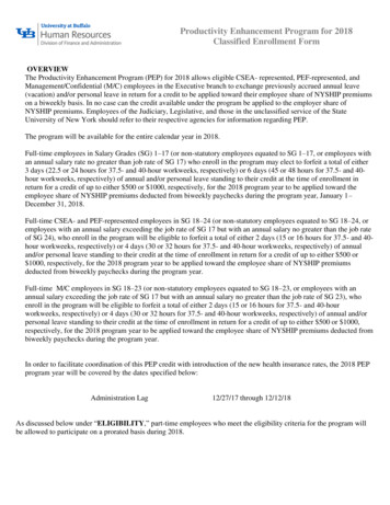
2 DISCUSSION - Theory2.1TheoryPrior to the commencement of the project, two setups of the GSDL were considered anddiscussed in meetings with the project sponsors. These two different setups of GSDL arethe Littrow and Littman configurations. Both of these setups involve an external cavitydiffraction grating that splits the diode laser output into several orders. The 0th order beamis used as the output, while the 1st order beam is reflected back into the diode as a sourceof feedback. The differences between the two configurations are presented in section2.2.2.An ECDL with a mode-hop free region of 100 GHz is possible in the industrialdevelopment environment [3]. However, engineering an ECDL with mode-hop free tuningover 2 GHz is a challenge in mechanical precision and accuracy within an undergraduateenvironment. The secondary goal in this project was to obtain a large enough mode-hopfree bandwidth to cover a span of 8 GHz from the master laser. This, ideally, isapproximately the width of the Rubidium Absorption Spectrum of the Rubidium-85 andRubidium-87 isotope gases.2.1.1Rubidium Electron TransitionSince much of the laser cooling applied at the QDG laboratory consists of coolingRubidium, the spectral features of Rubidium need to be discussed. Below is a figureshowing the 4 Doppler-broadened absorption dips of Rubidium. As can be seen from thefigure, these 4 dips cover a frequency bandwidth of approximately 8 GHz, centered at780.24 nm (384.6 THz). In order to analyze the mode-hop free region (section 2.2.4) ofthe GSDL, this spectrum is compared to that of the GSDL in order to determine the largespossible mode-hop free scan of the laser.9
2 DISCUSSION - TheoryFigure 4: Rubidium absorption spectrum displaying the four absorption peaks (or minimums) overa range of frequency. [9]2.1.2Grating Stabilized Diode LaserThe main requirement of this project consists of the design of an ECDL capable of tuningits frequency without mode-hops. This fine-tuning is established by designing a laser withan external cavity, diffraction grating and a mirror. The diffraction grating is used toreflect light onto a mirror, and back into the laser diode. By adjusting the length of thecavity or the angle of either the mirror or grating (depending on the configuration used),the laser can select the frequency that it will amplify. There are several existing designsfor GSLDs. The two most
The beam splitter between the isolator and the mirrors splits the beam towards Rubidium absorption segment as shown in Figure 11. Figure 10 (b): Peak Wavelength vs Knob Turn Number Figure 11: The setup after the beam splitter which is sent through a glass slide to separate the beam to Rubidium cell and feedback to a photo-detector (or power meter).