Transcription
ARCH 331Note Set 27.2F2016abnDesign of Isolated Square and Rectangular Footings (ACI 318-14)Notation:a equivalent square column size inspread footing design depth of the effective compressionblock in a concrete beamAg gross area, equal to the total areaignoring any reinforcementAreq area required to satisfy allowable stressAs area of steel reinforcement inconcrete designA1 area of column in spread footingdesignA2 projected bearing area of columnload in spread footing designb rectangular column dimension inconcrete footing design width, often cross-sectionalbf width of the flange of a steel orcross sectionbo perimeter length for two-way shearin concrete footing designB spread footing dimension inconcrete design dimension of a steel base plate forconcrete footing designBs width within the longer dimensionof a rectangular spread footing thatreinforcement must be concentratedwithin for concrete designc rectangular column dimension inconcrete footing designC dimension of a steel base plate forconcrete footing designd effective depth from the top of areinforced concrete member to thecentroid of the tensile steeldb bar diameter of a reinforcing bardf depth of a steel column flange(wide flange section)f c concrete design compressive stressfy yield stress or strengthhf height of a concrete spread footingld development length for reinforcing steell dclscLLm name for length or span length projected length for bending inconcrete footing designL’ length of the one-way shear area inconcrete footing designMn nominal flexure strength with thesteel reinforcement at the yieldstress and concrete at the concretedesign strength for reinforcedconcrete flexure designMu maximum moment from factoredloads for LRFD beam designP name for axial force vectorPdowels nominal capacity of dowels fromconcrete column to footing inconcrete designPD dead load axial forcePL live load axial forcePn nominal column or bearing loadcapacity in concrete designPu factored axial forceqallowable allowable soil bearing stress inallowable stress designqnet net allowed soil bearing pressurequ factored soil bearing capacity inconcrete footing design from loadfactorsVc shear force capacity in concreteVn nominal shear force capacityVu1 maximum one-way shear fromfactored loads for LRFD beam designVu2 maximum two-way shear fromfactored loads for LRFD beam design ratio of long side to short side of thecolumn in concrete footing designλ modification factor for lightweightconcreteϕ resistance factor c s c development length for column lap splice length in compression forreinforcement431 density or unit weight of concrete density or unit weight of soil reinforcement ratio in concretebeam design As/bd shear strength in concrete design
ARCH 331Note Set 27.2F2016abnNOTE: This procedure assumes that the footing is concentrically loaded and carries no moment so that the soilpressure may be assumed to be uniformly distributed on the base.1) Find service dead and live column loads:PD Service dead load from columnPL Service live load from columnP PD PL (typically – see ACI 5.3)2) Find design (factored) column load, Pu:PU 1.2PD 1.6PL3) Find an approximate footing depth, hfh f d 4" and is usually in multiples of 2, 4 or 6 inches.a) For rectangular columns4d 2 2(b c)d b) For round columnsd 2 ad Pu cPu ca d24where: a is the equivalent square column size c 4 fc for two-way shear 0.75 for shearλ 1.0 for normalweightconcrete4) Find net allowable soil pressure, qnet:By neglecting the weight of anyadditional top soil added, the netallowable soil pressure takes intoaccount the change in weight whensoil is removed and replaced by concrete:qnet qallowable hf ( c s ) c is the unit weight of concrete (typically 150 lb/ft3)whereand sis the unit weight of the displaced soil5) Find required area of footing base and establish length and width:Areq PqnetFor square footings choose B AreqFor rectangular footings choose B L Areq432
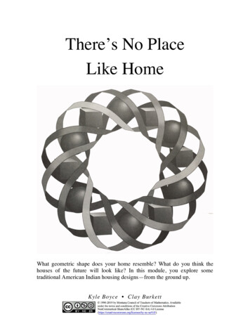
ARCH 331Note Set 27.2F2016abn6) Check transfer of load from column to footing: ACI 16.3a) Find load transferred by bearing on concrete in column: ACI 22.8basic: Pn 0.85 f c A1 where 0.65 and A1 is the area of the columnwith confinement: Pn 0.85 f c A1A2whereA1A2cannot exceed 2.A1IF the column concrete strength is lower than thefooting, calculate Pn for the column too.loaded area A1b) Find load to be transferred by dowels: Pdowels Pu PnIF Pn Pu only nominal dowels are required.c) Find required area of dowels and choose barsReq. dowel As A2 measured onthis plane Pdowelswhere 0.65 and fy is the reinforcement grade fyChoose dowels to satisfy the required area and nominal requirements:i) Minimum of 4 barsii) Minimum As 0.005 AgACI 16.3.4.1where Ag is the gross column aread) Check dowel embedment into footing for compression: ACI 25.4.9ldc f y db50 fc but not less than 0.0003 f y db or 8” where db is the bar diameterNOTE: The footing must be deep enough to accept ldc. Hooks are not considered effective in compressionand are only used to support dowels during construction.e) Find length of lapped splices of dowels with column bars: ACI 25.5.5lsc is the largest of:i)larger ofldc or0.0005 f y db (fy of grade 60 or less)of smaller bar (0.0009 f y 24)db (fy over grade 60)ii)ldc of larger bariii)not less than 12”See ACI 10.7.5 for possible reduction in lsc433
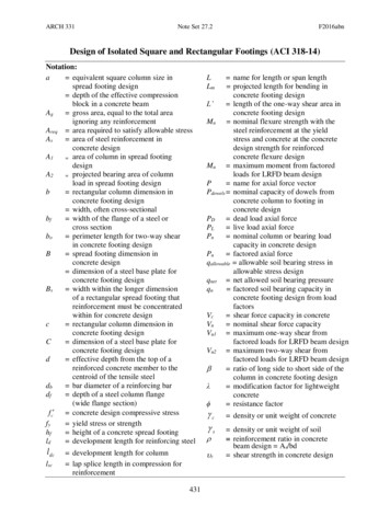
ARCH 331Note Set 27.2F2016abn7) Check two-way (slab) shear:a) Find dimensions of loaded area:i)ii)For concrete columns, the area coincideswith the column area, if rectangular, orequivalent square area if circular(see 3)b))For steel columns an equivalent loadedarea whose boundaries are halfwaybetween the faces of the steel columnand the edges of the steel base plate isused: ACI 13.2.7.1 b bf (B bf )where bf is the width of column flange and B is base plate side2c df (C d f )where df is the depth of column flange and C is base plate side2b) Find shear perimeter: ACI 22.6.4Shear perimeter is located at a distance of d2outside boundaries of loaded area andlength is bo 2(c d ) 2(b d )(average d hf – 3 in. cover – 1 assumed bar diameter)c) Find factored net soil pressure, qu:qu PuPuorB2B Ld) Find total shear force for two-way shear, Vu2:Vu 2 Pu qu (c d )(b d )e) Compare Vu2 to two-way capacity, Vn: 4 Vu2 2 fc bo d 4 fc bo d ACI 22.6.5.1 where 0.75 and is the ratio of long side to shortside of the columnNOTE: This should be acceptable because the initial footingsize was chosen on the basis of two-way shear limiting. If it isnot acceptable, increase h f and repeat steps starting at b). 434
ARCH 331Note Set 27.2F2016abn8) Check one-way (beam) shear:The critical section for one-way shear extends across thewidth of the footing at a distance d from the face of theloaded area (see loaded area). The footing is treated as acantilevered slab. ACI 7.4.3.2a) Find projection, L’:i) For square footing:L B (d b 2) where b is the smaller dim. of2the loaded areaii) For rectangular footings:L L (d 2) where is the dim. parallel to2the long side of the footingb) Find total shear force on critical section, Vu1:Vu1 BL quc) Compare Vu1 to one-way capacity, Vn: Vu1 2 fc Bd ACI 22.5.5.1where 0.75NOTE: If it is not acceptable, increase h f .9) Check for bending stress and design reinforcement:Square footings may be designed for moment in one direction and the same reinforcing usedin the other direction. For rectangular footings the moment and reinforcing must becalculated separately in each direction. The critical section for moment extends across thewidth of the footing at the face of the loaded area. ACI 13.2.7.1a) Find projection, Lm:Lm B 2 2where is the smaller dim. of column for a square footing. Fora rectangular footing, use the value perpendicular to the criticalsection.b) Find total moment, Mu, on critical section:M u quBL2m2(find both ways for a rectangular footing)435
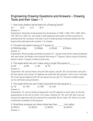
ARCH 331Note Set 27.2F2016abnc) Find required As:Rn MnMu, where 0.9, and can be found 2bd bd 2from Figure 3.8.1 of Wang & Salmon.or: i) guess aii) As 0.85 f c bafy iii) solve for a 2 d M u As f y iv) repeat from ii) until a converges, solve for As Minimum As 0.0018bhGrade 60 for temperature and shrinkage control 0.002bhGrade 40 or 50ACI 7.6.1.1 specifies the requirements of ACI 7.6.4 must be met, and max. spacing of 18”d) Choose bars:For square footings use the same size and number of bars uniformly spaced in eachdirection (ACI 13.3.3.2). Note that required As must be furnished in each direction.For rectangular footings bars in long direction should be uniformly spaced. In the shortdirection bars should be distributed as follows (ACI 13.3.3.3):i) In a band of width Bs centered on column:# bars 2 (# bars in B) (integer)L 1Bii)Remaining bars in short direction should beuniformly spaced in outer portions of footing.e) Check development length:Find required development length, ld, in tension fromhandout or from equations in ACI 25.4. ld must be lessthan (Lm – 2”) (end cover). If not possible, use more bars of smaller diameter.436
ACI 7.6.1.1 specifies the requirements of ACI 7.6.4 must be met, and max. spacing of 18" d) Choose bars: For square footings use the same size and number of bars uniformly spaced in each direction (ACI 13.3.3.2). Note that required A s must be furnished in each direction. For rectangular footings bars in long direction should be uniformly spaced.


![BCA160 Macrame [2015] - NDSU](/img/19/bca160.jpg)