Transcription
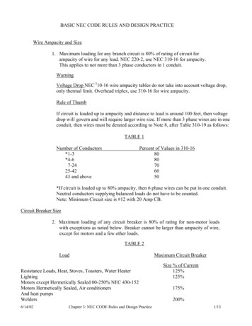
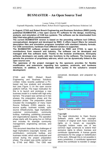
0.1. Source Shifting & Transformation Techniques0.1Source Shifting & Transformation Techniques1 Use source shifting and transformation techniquesto find voltage across 2 Ω resistor as shown in Figure12A2 1A43 3A44 Figure 54 1 2A4 3A2 2 - 3V2 Figure 6The voltage across 2 Ω resistor isFigure 1: 2018-DEC2 1.5 A2 2 1.5 2 3VI 3VSolution:3V -3 1 3V -4 2A2 Use source shifting and transformation techniquesto find voltage across a, b resistor as shown in Figure73 2 2A6 Figure 23V -3 2V -1 4 b5AaI18 2 3V -Figure 7: 2018-DEC2 2A9 Solution:3 Figure 31V -4 4 2A2 Figure 43V -6 9 5A5Aba8 2 Figure 8Dr. Manjunatha P Prof., Dept of ECE, JNN College of Engg Shimoga manjup.jnnce@gmail.com1
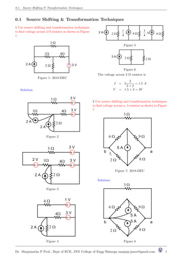
0.1. Source Shifting & Transformation Techniques3 60 Vc3 6 6 9 30 V 15 12 b a10 V-a- 8 8 2 bFigure 9Figure 12: 2018-DEC3 Solution:2A15 b60 Vca- - 60 Va1A12 3 6 15 8 10 bFigure 13Figure 103 a2 10 A6 ba15 12 4A1A8 bFigure 11Figure 14The voltage across a, b resistor isa2 3 0.3333 A6 3 0.3333 6 2VI 1V20 V 15 12 3 Use source shifting and transformation techniquesto find voltage across a, b resistor as shown in Figure124A8 bDr. Manjunatha P Prof., Dept of ECE, JNN College of Engg Shimoga manjup.jnnce@gmail.com2
0.1. Source Shifting & Transformation Techniques18 Figure 15Vxa3 10 15 2A15 V 15 V- -7 15 V6 12 - 30 V-6 4 4A3 18 bVx10 Figure 163Aa5A4 6A10 b2 18 The voltage across a, bresistor isVx 6 4 24VV 15 V4 Use source shifting and transformation techniquesto find voltage across a, b resistor as shown in Figure125 2 - 10 VThe voltage across 18Ω resistor is5 0.2A25 0.2 15 3.6Vi 18 VVx3 7 3 -5A6 15 V6 4 DEC 2018 (2017 scheme) DEC 2018 (2015 scheme)1 a) Reduce the network shown in Figure 17 to asingle voltage source in series with a resistance usingsource shift and source transformations.Solution:8 3 2 ASolution:45 A18 3 15 V 15 V7 - -10 3 6 5A5A4 6 5 VxB30 V -6 Figure 17: 2018-DECThe modified circuit diagram is as shown in Figure18 by shifting the voltage and current sources.Dr. Manjunatha P Prof., Dept of ECE, JNN College of Engg Shimoga manjup.jnnce@gmail.com3
0.1. Source Shifting & Transformation Techniques8 30 V -60 VB- - 3 2 5 A16 60 V90 A30 V -45 AB12 6 90 A10 20 Figure 23Figure 18- -3 2 - A225 VB900 V5 60 V6 4 A- - -90 V16 60 V360 V30 V- 8 30 V-45 A6 4 10 AB10 12 6 20 10 Figure 24Figure 1920 10 3 6AA15 AA10 A6 10 AB15 12 30 A6 15 AFigure 254 A 12 - 180 V2 B -- 54 V20 VA34 V- AB40 V8 B140 V 16 - 6 -Figure 20AB30 BFigure 26Figure 21Aug 2020 (2018 scheme EE) 2 c) Apply sourcetransformation and shifting method to reduce theAug 2020 (2018 scheme EE) 2 c) Apply source network shown in Figure 27 to a single voltage sourcetransformation and shifting method to reduce the in series with a resistance.network shown in Figure 22 to a single voltage sourceSolution:in series with a resistance.3 Solution:16 A10 20 1 B60 V -90 A4 6 4 12 Figure 22: 2018-DEC18 V -2 6 VxFigure 27: 2018-DECDr. Manjunatha P Prof., Dept of ECE, JNN College of Engg Shimoga manjup.jnnce@gmail.com4
0.1. Source Shifting & Transformation Techniques18 V- 18 V- 6V- 3 6A4 1.333 3 Figure 30Vx6 Vx6 1 2 1 6AFigure 283 2.57 A2.333 Vx6 Figure 318.57 A1.312 6 Vx1 6A3 4.5 A4 Figure 292 6 VxFigure 32I 8.571.312 1.352 A1.312 7Dr. Manjunatha P Prof., Dept of ECE, JNN College of Engg Shimoga manjup.jnnce@gmail.com5
0.1 Source Shifting & Transformation Techniques 1Use source shifting and transformation techniques to nd voltage across 2 resistor as shown in Figure 1 : 9 : : : Figure 1: 2018-DEC Solution: : : : : 9 9 Figure 2 : : : : 9 9 9 Figure 3 : : : 9 9 Figure 4 : : Figure 5 : : Figure 6 The voltage across 2 resistor is I 3 2 2 2 .