Transcription
Falcon 9 Launch VehiclePayload User’s GuideRev1Approved for Public Release.Cleared for Open Publication by Office of Security Review. 09-S-0347 Space Exploration Technologies Corporation
Falcon 9 User’s GuideTable of ContentsTable of Contents21.Introduction1.1. Revision History1.2. Purpose1.3. Company Description1.4. Falcon Program Overview1.5. Mission Management1.6. Key Customer Advantages1.6.1. Reliability1.6.2. Pricing4444555572.Vehicle Overview2.1. Falcon 9 Launch Vehicles2.1.1. Structure and Propulsion2.1.2. Avionics, Guidance/Navigation/Control,Systems 82.2. Vehicle Axes/Attitude DefinitionsFlight888Termination113.Facilities Overview123.1. Headquarters – Hawthorne, CA123.2. Space Launch Complex 40, Cape Canaveral Air Force Station, Florida123.3. Space Launch Complex ‐ 4 East, Vandenberg Air Force Base (VAFB),California153.4. U.S. Army Kwajalein Atoll, Marshall Islands163.5. Test Facility ‐ Central Texas173.6. Government Outreach and Legal Affairs‐‐Washington, DC174.General Performance Capability184.1. Performance Capability184.1.1. Low Earth Orbit194.1.2. Polar204.1.3. Sun Synchronous214.1.4. C3 – Escape Velocity224.1.5. Geosynchronous Transfer Orbit (Cape Canaveral)234.1.6. Geosynchronous Transfer Orbit (Kwajalein)244.1.7. Geosynchronous Transfer Orbit (Delta‐Velocity To Go) [Cape] 254.1.8. Geosynchronous Transfer Orbit (Delta‐Velocity To Go)[Kwajalein]264.2. Sample Mission Profiles274.3. Mass Properties294.4. Separation Accuracy294.5. Mission Accuracy Data29SCM 2008‐010 Rev. 1Copyright ‐‐ SpaceX 20092
Falcon 9 User’s Guide5.General Payload Information5.1. Payload Fairing5.1.1. General Description5.1.2. Falcon 9 Fairing5.1.3. Payload Separation5.1.4. Collision Avoidance5.2. Payload Environments5.2.1. Transportation Environments5.2.2. Humidity, Cleanliness and Thermal Control5.2.3. Launch and Flight Environments5.3. Payload Interfaces5.3.1. Falcon 9 Payload Attach Fittings5.3.2. Test Fittings and Fitcheck Policy5.3.3. Electrical Interfaces5.4. Payload Integration5.4.1. Integration Schedule5.4.2. Documentation Requirements5.4.3. Standard Services5.4.4. Non‐standard unch Operations6.1. Launch Control Organization6.2. Spacecraft Transport to Launch Site6.2.1. Processing Services and Equipment6.3. Plans and Schedules6.3.1. Mission Integration Plan6.3.2. Launch Vehicle Schedules525355555759607.Safety7.1. Safety Requirements7.2. Hazardous Systems and Operations7.3. Waivers616161618.Payload Questionnaire629.Quick Reference9.1. List of Figures9.2. List of Tables9.3. List of Acronyms63636464SCM 2008‐010 Rev. 1Copyright ‐‐ SpaceX 20093
Falcon 9 User’s Guide1. Introduction1.1. Revision HistoryThis is the first publicly available version of the Falcon 9 Launch Vehicle User's Guide.1.2. PurposeThe Falcon 9 User’s Guide is a planning document provided for potential and current customersof Space Exploration Technologies (SpaceX). This document is not intended for detailed designuse. Data for detailed design purposes will be exchanged directly between a SpaceX MissionManager and the Payload Provider. This User's Guide highlights the Falcon 9 Block 2 launchvehicle and launch service. The Block 2 launch vehicle offers improved mass‐to‐orbitperformance when compared to the Falcon 9 Block 1. Specific differences between Block 1 andBlock 2 will be identified, when appropriate. Performance and environments information arebased upon Falcon 9 requirements and analyses, but are not yet validated by flight data.1.3. Company DescriptionIn an era when most technology‐based products follow a path of ever‐increasing capability andreliability while simultaneously reducing costs, today’s launch vehicles are little changed fromthose of 40 years ago. SpaceX is changing this paradigm with a family of launch vehicles whichwill ultimately reduce the cost and increase the reliability of access to space. Coupled with thenewly emerging market for private and commercial space transport, this new model will re‐ignite humanity's efforts to explore and develop space.SpaceX was founded on the philosophy that simplicity, reliability, and low‐cost are closelycoupled. We approach all elements of launch services with a focus on simplicity to bothincrease reliability and lower cost. The SpaceX corporate structure is flat and businessprocesses are lean, resulting in both fast decision making and delivery. SpaceX products aredesigned to require low infrastructure facilities (production and launch) with low maintenanceoverhead, while vehicle design teams are co‐located with production and quality assurancestaff to tighten the critical feedback loop. The result is highly producible and low cost designswith quality imbedded. To better understand how SpaceX can achieve low cost withoutsacrificing reliability, please see the Frequently Asked Questions at www.spacex.com.Established in 2002 by Elon Musk, the founder of PayPal and the Zip2 Corporation, SpaceX hasalready developed a light lift launch vehicle, the Falcon 1, nearly completed development of theFalcon 9, and developed state of the art testing and launch locations.In addition, NASA has selected the SpaceX Falcon 9 launch vehicle and Dragon spacecraft forthe International Space Station (ISS) Cargo Resupply Services (CRS) contract award. Thecontract is for a guaranteed minimum of 20,000 kg to be carried to the International SpaceStation. The firm contracted value is 1.6 billion and NASA may elect to order additionalmissions for a cumulative total contract value of up to 3.1 billion. SpaceX is on sound financialfooting as we move towards volume commercial launches.SCM 2008‐010 Rev. 1Copyright ‐‐ SpaceX 20094
Falcon 9 User’s GuideOur design and manufacturing facilities are conveniently located near the Los AngelesInternational airport. This location also allows the company to leverage the deep and richaerospace talent pool available in Southern California. The SpaceX state‐of‐the‐art propulsionand structural test facilities are located in Central Texas.1.4. Falcon Program OverviewDrawing upon a rich history of prior launch vehicle and engine programs, SpaceX is privatelydeveloping the Falcon family of rockets from the ground up, including main and upper‐stageengines, the cryogenic tank structure, avionics, guidance & control software and groundsupport equipment.With the Falcon 1, Falcon 1e, Falcon 9 and Falcon 9 Heavy launch vehicles, SpaceX is able tooffer a full spectrum of light, medium and heavy lift launch capabilities to our customers. Weare able to deliver spacecraft into any inclination and altitude, from low Earth orbit (LEO) togeosynchronous orbit (GEO) to planetary missions. The Falcon 9 and Falcon 9 Heavy are theonly US launch vehicles with true engine‐out reliability. They are also designed such that allstages are reusable, making them the world's first fully reusable launch vehicles. The Dragoncrew and cargo capsule, in conjunction with our Falcon 9, have been selected by NASA toprovide efficient and reliable transport of cargo and potentially crew to the International SpaceStation (ISS) and other LEO destinations.1.5. Mission ManagementTo facilitate and streamline communication, each customer works with a single SpaceX contact,a Mission Manager. The Mission Manager works closely with the customer, SpaceX technicalexecution staff and all associated licensing agencies in order to achieve a successful mission.Specifically, the SpaceX Mission Manager is responsible for coordinating mission integrationanalysis and documentation deliverables, planning integration meetings and reports, andcoordinating all integration and test activities associated with the mission.The Mission Manager will also facilitate customer insight during the launch campaign. Thoughthe launch operations team is ultimately responsible for customer hardware and associatedGround Support Equipment (GSE), the Mission Manager will coordinate all launch site activitiesto ensure customer satisfaction during this critical phase.1.6. Key Customer Advantages1.6.1. ReliabilityThe vast majority of launch vehicle failures in the past two decades can be attributed to threecauses: engine, avionics and stage separation failures. An analysis by Aerospace Corporation1showed that 91% of known failures can be attributed to those link/winter2001/03.html. A hard copy of this reference can be madeavailable upon request.SCM 2008‐010 Rev. 1Copyright ‐‐ SpaceX 20095
Falcon 9 User’s GuideWith this in mind, Falcon 9 launch vehicles are designed for high reliability starting at thearchitectural level and incorporate the flight‐proven design and features of the Falcon 1 launchvehicle. Some of the significant contributors to reliability include: Robust design marginsFalcon 9 is designed with the goal of carrying humans into space aboard the SpaceXDragon capsule. This goal drives the initial design of Falcon 9 through the incorporationof increased factors of safety (1.4 versus the traditional 1.25 for uncrewed flight).Payload customers using the Falcon 9 can take advantage of this increased designrobustness. The first and second stages are also designed to be recovered and reused,and therefore, must have significantly higher margins than an expendable stage. Thisalso provides a unique opportunity to examine recovered hardware and assess designand material selection in order to continually improve Falcon 9. Propulsion and separation event designThe heart of Falcon 9 propulsion is the Merlin 1C liquid propellant rocket engine. TheMerlin engine features a robust, reliable turbopump design incorporating a single shaftfor both the liquid oxygen and fuel pumps, and a gas generator cycle versus the morecomplex staged combustion. The regeneratively‐cooled thrust chamber uses a milledcopper alloy liner chamber that provides large margins on heat flux. In addition, thepintle injector was selected for its inherent combustion stability. As a part of our launchoperations, we hold the first stage after ignition and monitor engine prior to release towatch engine trends. If an off‐nominal condition exists, an autonomous abort isconducted. This helps prevent an engine performance issue from causing a failure inflight. Falcon 9 makes use of ten Merlin 1C engines on each vehicle (nine on the firststage, one on the second stage) resulting in high volume engine production, whichresults in much higher quality through process control. Flying ten engines on eachmission also builds substantial heritage quickly. Importantly, by employing nine firststage engines, SpaceX debuts the world’s first Evolved Expendable Launch Vehicle(EELV)‐class launch vehicle with engine‐out capability through much of first stage flight.With the qualification and first flight units in build and several domestic andinternational purchased flights currently manifested, Falcon 9 is an ideal workhorse forpayload customers.SpaceX has also minimized the number of stages (2) to minimize separation events. Theseparation system between the first and second stages does not incorporate electro‐explosive devices, instead relying upon a pneumatic release and separation system thatallows for acceptance testing of the actual flight hardware. This is not possible with atraditional explosive‐based separation system. Failure mode minimizationSpaceX minimized the number of failure modes by minimizing the number of separatesubsystems. The first stage thrust vector control (TVC) system makes use of pressurizedSCM 2008‐010 Rev. 1Copyright ‐‐ SpaceX 20096
Falcon 9 User’s Guiderocket‐ grade kerosene (RP‐1). The engine pulls from the high pressure RP‐1 side of thepump to power the TVC. This eliminates the separate hydraulic system. In addition iteliminates the failure mode associated with running out of pressurized fluid. Also, theavionics and guidance/navigation/control systems are designed with single faulttolerance, supporting the ability of Falcon 9 to be human rated. Rigorous testingIn addition to SpaceX’s unique design decisions, Falcon 9 will undergo an exhaustiveseries of tests from the component to the vehicle system level. This includescomponent level qualification and workmanship testing, structures load and prooftesting, flight system and propulsion subsystem level testing, full first and second stagetesting up to full system testing, including stage static firings at the test and launch sites(as appropriate). In addition to testing environmental extremes (plus margin), allhardware is tested to account for off‐nominal conditions. For example, both stage andfairing separation tests require testing for off‐nominal cases with respect to geometricalmisalignment, anomalous pyro timing and sequencing.A major contributor to a reliable system is its operations. To support robust launch operations,the SpaceX launch countdown is fully automated with thousands of checks made prior tovehicle release. After first stage ignition, the vehicle is not released until the first stage enginesare confirmed to be operating normally. A safe shutdown is executed, should any off nominalconditions be detected. Falcon 9 benefits from the design and operations concepts establishedfor and proven with the successful Falcon 1 program.1.6.2. PricingThe standard price per launch for Falcon 9 Launch Vehicles can be found here2. Pricing includesrange, standard payload integration and third party liability insurance. Please see Section 5.4for a description of the standard services. Non‐standard services are also available. If non‐standard services are required, please identify these in the Payload Questionnaire found inSection 8 of this Guide.2http://www.spacex.com/falcon9.php#pricing and performance.SCM 2008‐010 Rev. 1Copyright ‐‐ SpaceX 20097
Falcon 9 User’s Guide2. Vehicle Overview2.1. Falcon 9 Launch VehiclesFalcon 9 Launch Vehicles are designed to provide breakthrough advances in reliability, cost, andtime to launch. The primary design driver is, and will remain, reliability. SpaceX recognizes thatnothing is more important than getting a customer’s payload safely to its intended destination.The initial flights of the Falcon 9, currently planned in 2009 and 2010, use the Falcon 9 Block 1.Beginning in late 2010/early 2011, SpaceX will begin launching the Falcon 9 Block 2. Block 2features increased engine thrust, decreased launch vehicle dry mass, and increased propellantload ‐ combined with lessons learned from the flights of the Falcon 9 Block 1. This results inincreased mass‐to‐orbit performance for the Falcon 9 Block 2 when compared with Block 1performance. This performance is shown in the Falcon 9 performance tables presented later inthis document.2.1.1. Structure and PropulsionLike Falcon 1, Falcon 9 is a two‐stage, liquid oxygen (LOX) and rocket grade kerosene (RP‐1)powered launch vehicle. It uses the same Merlin engines, structural architecture (with a widerdiameter), and launch control system.The Falcon 9 propellant tank walls and domes are made from an aluminum lithium alloy.SpaceX uses an all friction stir welded tank, the highest strength and most reliable weldingtechnique available. Like Falcon 1, the Falcon 9 interstage, which connects the upper and lowerstages, is a carbon fiber aluminum core composite structure. The separation system is a largerversion of the pneumatic pushers used on Falcon 1.Nine SpaceX Merlin engines power the Falcon 9 first stage with 125,000 lbf sea level thrust perengine, for a total thrust on liftoff of just over 1.1 million lbf. After engine start, Falcon 9 is helddown until all vehicle systems are verified as functioning normally before release for liftoff.The second stage tank of Falcon 9 is simply a shorter version of the first stage tank and usesmost of the same tooling, material and manufacturing techniques. This results in significant costsavings in vehicle production.A single Merlin engine powers the Falcon 9 upper stage with an expansion ratio of 117:1 and anominal burn time of 345 seconds. For added reliability of restart, the engine has dualredundant pyrophoric igniters (TEA‐TEB).The Falcon 9 fairing is 17 ft (5.2 m) in diameter.2.1.2. Avionics, Guidance/Navigation/Control, Flight Termination SystemsFalcon 9 vehicle avionics features a single‐fault tolerant architecture and has been designedwith a view towards human‐rating requirements in order to allow future qualification forSCM 2008‐010 Rev. 1Copyright ‐‐ SpaceX 20098
Falcon 9 User’s Guidecrewed launch capability. Avionics include rugged flight computers, GPS receivers, inertialmeasurement units, SpaceX‐designed and manufactured controllers for vehicle control(propulsion, valve, pressurization, separation, and payload interfaces), and a C‐Bandtransponder for Range Safety tracking. Falcon 9 transmits telemetry from both the first andsecond stages, even after separation of the stages. S‐band transmitters are used to transmittelemetry and video to the ground.The guidance and navigation algorithms for Falcon 9 launch vehicles have been heavilyinfluenced by the algorithms used on other launch vehicles, including Falcon 1. The guidancesystem takes into account the loss of an engine during first stage burn and adjusts the targetedtrajectory accordingly. This mix of explicit and perturbation guidance schemes was selected inorder to generate a smooth, computationally simple trajectory while maintaining orbitalinsertion accuracies.The Falcon 9 launch vehicle is equipped with a standard flight termination system. This systemincludes two redundant strings of command receiver and encoder, batteries, safe and armdevices, and ordnance in the event of an anomaly in flight.SCM 2008‐010 Rev. 1Copyright ‐‐ SpaceX 20099
Falcon 9 User’s GuideTable 2‐1 ‐ Falcon 9 Launch Vehicle (Block 2) Dimensions and erTypeMaterialPropulsionEngine TypeEngine ManufacturerEngine DesignationNumber of enginesPropellantThrustPropellant feed systemThrottle capabilityRestart capabilityTank pressurizationThrust Vector ControlPitch, YawRollReaction Control SystemPropellantThrustersThrustStagingNominal burn timeShutdown processStage separation systemSCM 2008‐010 Rev. 1Stage 1Stage 2180 feet [55m] (both stages with fairing & interstage)12 feet [3.66m]LOX tank ‐ monococque; FuelMonococquetank ‐ stringer and ring frameAluminum lithiumAluminum lithiumLiquid, gas generatorSpaceXMerlin 1C9Liquid oxygen/Kerosene (RP‐1)1,125,000 lbf (sea level) [5MN]TurbopumpNoNoHeated heliumLiquid, gas generatorSpaceXMerlin Vacuum1Liquid oxygen/Kerosene (RP‐1)100,000 lbf (vacuum) [445kN]TurbopumpYes (60‐100%)Yes ‐ 2 restartsHeated heliumGimbaled enginesGimbaled enginesGimbaled engineTurbine exhaust duct (gimbal)Not applicableMonomethyl hydrazine,nitrogen tetroxideDraco (4)90 lbf [400N] eachNot applicableNot applicable170 secCommanded shutdownPneumatically actuatedmechanical colletsCopyright ‐‐ SpaceX 2009354 secCommanded shutdownNot applicable10
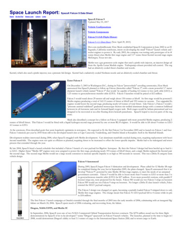
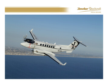
Falcon 9 User’s Guide2.2. Vehicle Axes/Attitude DefinitionsTrue North(10 deg app .)Notes‐ Vehicle as seen from above‐ Vehicle coordinate frame as shown, with the Xaxis being the vehicle longitudinal axis, positiveforward . This coordinate frame is aligned withthe Erector Z (0 deg)Positive ClockingAngle9S ‐Band60 deg63Q IVUHF300 degFairing Split Line292 .5 degC ‐Band 270 degC Band90 deg8QI5Q III2 Y30 . 8 7UHF120 degTAA ‐3C(Telemetry )Q II4FPS 16 (Radar )1FTSTransmitterS ‐Band 240 degJD Missile TrackingAnnexTransporter /ErrectorFigure 2‐1 ‐ Falcon 9 launch vehicle layout and coordinate systemSCM 2008‐010 Rev. 1Copyright ‐‐ SpaceX. 200911
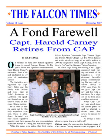
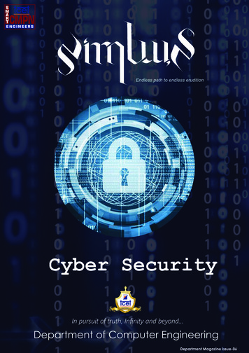
Falcon 9 User’s Guide3. Facilities Overview3.1. Headquarters – Hawthorne, CASpaceX headquarters are conveniently located in Hawthorne, CA, a few miles inland from LosAngeles International Airport (LAX). The 550,000 square foot (5.1 hectares) design andmanufacturing facility ranks among the largest manufacturing facilities in California. Twocomplete Falcon 9s will fit end‐to‐end along the short length of the building. For production,there are three Falcon 1 lines, three parallel Falcon 9 lines, nearly two dozen Merlin engineassembly stations, and Dragon capsule production areas. Potential customers are encouragedto arrange a tour when in the Los Angeles area. Map and Directions.Figure 3‐1‐ Hawthorne, California Headquarters3.2. Space Launch Complex 40, Cape Canaveral Air Force Station, FloridaSpaceX has a Falcon 9 launch site on Cape Canaveral Air Force Station (CCAFS). The launch siteis Space Launch Complex 40 (SLC‐40), former home of the Titan IV heavy lift rockets. SpaceXfacilities at SLC‐40 include a hangar, propellant/pressurant storage and supply areas, launchpad, and lightning towers. Adjacent to the launch complex is the SpaceX administrative officefacility. SpaceX launch operations are managed from the Launch Control Center, located at thesouth entrance to CCAFS. A general layout of the launch facilities is presented in the followingfigures.Figure 3‐2 ‐ Launch Complex 40 at Cape Canaveral Air Force Station (CCAFS), FloridaSCM 2008‐010 Rev. 1Copyright ‐‐ SpaceX 200912
Falcon 9 User’s GuideFigure 3‐3 ‐ Space Launch Complex 40 Instrumentation Bay locationSCM 2008‐010 Rev. 1Copyright ‐‐ SpaceX 200913
Falcon 9 User’s GuideFigure 3‐4 ‐ Space Launch Complex 40 Hangar layoutSCM 2008‐010 Rev. 1Copyright ‐‐ SpaceX 200914
Falcon 9 User’s Guide3.3. Space Launch Complex ‐ 4 East, Vandenberg Air Force Base (VAFB), CaliforniaSpaceX plans to establish a launch facility at Vandenberg Air Force Base (VAFB) in centralCalifornia to meet customer needs for polar and sun‐synchronous capability. SpaceX’sheadquarters, manufacturing and production facility is located in the Los Angeles area, withindriving distance or a short flight to VAFB. SpaceX has previously worked with the Range atVAFB on Falcon 1 facilities, including conducting a static fire at SLC‐3 West in 2005. Thecandidate launch site, pending discussions with the U.S. Air Force, would be at Space LaunchComplex 4 East (SLC‐4E). The design of the Falcon 9 launch site at VAFB will mirror the facilitiesand operations implemented at the Cape Canaveral launch site.Figure 3‐5 ‐ SLC‐4 East, VAFBSCM 2008‐010 Rev. 1Copyright ‐‐ SpaceX 200915
Falcon 9 User’s Guide3.4. U.S. Army Kwajalein Atoll, Marshall IslandsSpaceX has an operational Falcon 1 launch site at the Kwajalein Atoll, about 2500 milessouthwest of Hawaii. The Falcon 1 launch facilities are situated on Omelek Island, part of theRonald Reagan Ballistic Missile Defense Test Site (RTS) at United States Army Kwajalein Atoll(USAKA). The location and a general layout of the launch facility are presented in Figure 3‐6.SpaceX is evaluating establishing a launch facility for Falcon 9 at Kwajalein that would providesuperior performance to geosynchronous transfer orbit as well as high‐inclination orbits.Figure 3‐6 ‐ Falcon 1 launch site, Kwajalein AtollSCM 2008‐010 Rev. 1Copyright ‐‐ SpaceX 200916
Falcon 9 User’s Guide3.5. Test Facility ‐ Central TexasStructural and propulsion tests are conducted at the rapidly growing and expanding test sitelocated in McGregor, Texas, just west of Waco. Conveniently located 2 hours from both Austinand Dallas, the site is staffed with test engineers, technicians and management personnel.During preparation and testing, the site also plays host to personnel from the Californiaheadquarters who supplement the Texas team.Figure 3‐7 ‐ SpaceX’s Texas Test Facility3.6. Government Outreach and Legal Affairs‐‐Washington, DCSpaceX’s government outreach and licensing team is located in Washington, DC.SCM 2008‐010 Rev. 1Copyright ‐‐ SpaceX 200917
Falcon 9 User’s Guide4. General Performance Capability4.1. Performance CapabilityThe Falcon 9 launch vehicle performance presented in the following tables and figures is for theBlock 2 (see paragraph 2.1.2 for details). The performance shown is the maximum capability ofthe Falcon 9 Block 2 with margin withheld by SpaceX to ensure mission success. Please notetypical payloads in the Falcon 9 class typically below 15000 lbs (6800 kg). Potential customersshould contact SpaceX if they contemplate flying extra‐heavy payloads or using most of thelisted performance of the Falcon 9.For reference, the following is a list of tables and figures in this section:Section 4.1 List of FiguresFigure 4‐1 ‐ Falcon 9 Block 2 Performance to Low Earth Orbit (Cape Canaveral) . 19Figure 4‐2 ‐ Falcon 9 Block 2 Performance ‐ Circular Polar Orbit . 20Figure 4‐3 ‐ Falcon 9 Block 2 Performance ‐ Sun Synchronous Orbit . 21Figure 4‐4 ‐ Falcon 9 Block 2 Performance ‐ Escape Velocity (Cape Canaveral) . 22Figure 4‐5 ‐ Falcon 9 Block 2 Performance to Geosynchronous Transfer Orbit . 23Figure 4‐6 ‐ Falcon 9 Block 2 Performance to Geosynchronous Transfer Orbit (Kwajalein) . 24Figure 4‐7 ‐ Geosynchronous Transfer Orbit (Delta‐Velocity to Go) from Cape . 25Figure 4‐8 ‐ Geosynchronous Transfer Orbit (Delta‐Velocity to Go) from Kwaj . 26Figure 4‐9 ‐ Falcon 9 Sample Flight Profile, Geosynchronous Transfer Orbit Mission . 27Section 4.1 List of TablesTable 4‐1 ‐ Falcon 9 Block 2 Performance to Low Earth Orbit (Cape Canaveral) . 19Table 4‐2 Falcon 9 Block 2 Performance ‐ Circular Polar Orbit . 20Table 4‐3 ‐ Falcon 9 Block 2 Performance ‐ Sun Synchronous Orbit . 21Table 4‐4 ‐ Falcon 9 Block 2 Performance ‐ Escape Velocity (Cape Canaveral) . 22Table 4‐5 ‐ Falcon 9 Block 2 Performance to Geosynchronous Transfer Orbit . 23Table 4‐6 ‐ Falcon 9 Block 2 Performance to Geosynchronous Transfer Orbit (Kwajalein) . 24Table 4‐7 ‐ Geosynchronous Transfer Orbit (Delta‐Velocity to Go) from Cape . 25Table 4‐8 ‐ Geosynchronous Transfer Orbit (Delta‐Velocity to Go) from Kwaj . 26Table 4‐9 ‐ Falcon 9 Sample Flight Timeline, Geosynchronous Transfer Orbit Mission . 28SCM 2008‐010 Rev. 1Copyright ‐‐ SpaceX 200918
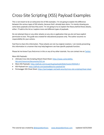
Falcon 9 User’s Guide4.1.1. Low Earth Orbit1200010000Payload Mass (kg)8000600040002000005001000150020002500Circular Altitude (km)51.6 deg38 deg28.5 degFigure 4‐1 ‐ Falcon 9 Block 2 Performance to Low Earth Orbit (Cape Canaveral)Table 4‐1 ‐ Falcon 9 Block 2 Performance to Low Earth Orbit (Cape Canaveral)Circular OrbitAltitude (km)2003004005006007008009001000Payload Mass (kg)Inclination 728522887986768331868784868148SCM 2008‐010 Rev. 1Circular OrbitAltitude ght ‐‐ SpaceX 2009Payload Mass (kg)Inclination 02873647187688872217048675370856913662219
Falcon 9 User’s Guide4.1.2. Polar1200010000Payload Mass (kg)8000600040002000005001000150020002500Circular Altitude (km)60 deg70 deg80 deg90 degFigure 4‐2 ‐ Falcon 9 Block 2 Performance ‐ Circular Polar OrbitTable 4‐2 Falcon 9 Block 2 Performance ‐ Circular Polar OrbitCircular OrbitAltitude (km)2003004005006007008009001000Payload Mass (kg)Inclination (degrees)60959893929166894887388535834081537972SCM 2008‐010 Rev. 597741872467079Circular OrbitAltitude ght ‐‐ SpaceX 2009Payload Mass (kg)Inclination 47263326198606959435820570220
Falcon 9 User’s Guide4.1.3. Sun Synchronous900080007000Payload Mass ircular Orbit Altitude (km)Figure 4‐3 ‐ Falcon 9 Block 2 Performance ‐ Sun Synchronous OrbitTable 4‐3 ‐ Falcon 9 Block 2 Performance ‐ Sun Synchronous OrbitCircular OrbitAltitude (km)2003004005006007008009001000SCM 2008‐010 Rev. 9.099.5PayloadMass (kg)835181597949774275417348716269816807Circular OrbitAltitude ght ‐‐ SpaceX 2.5103.1103.7104.3104.9PayloadMass (kg)663964766319616660175874573556005468534021
Falcon 9 User’s Guide4.1.4. C3 – Escape Velocity450040003500Payload Mass 3 (km 2/s 2)Figure 4‐4 ‐ Falcon 9 Block 2 Performance ‐ Escape Velocity (Cape Canaveral)Table 4‐4 ‐ Falcon 9 Block 2 Performance ‐ Escape Velocity (Cape Canaveral)C3(km 2/s 2)‐16‐14‐11‐8‐6‐30Payload Mass (kg)Escape Energy PerformanceCape Canaveral3823359833733148292326982473SCM 2008‐010 Rev. 1C3(km 2/s 2)471114192328333945Copyright ‐‐ SpaceX 2009Payload Mass (kg)Escape Energy PerformanceCape Canaveral22482023179815731348112389867344822322
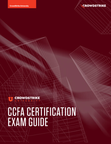
Falcon 9 User’s Guide4.1.5. Geosynchronous Transfer Orbit (Cape Canaveral)80007000Payload Mass (kg)6000500028.5 Inclination23 deg inclination400021 deg inclination19 deg inclination300017 deg inclination15 deg 0700008000090000100000Apogee Altitude (km) with 185 km perigee (Cape Canaveral)Figure 4‐5 ‐ Falcon 9 Block 2 Performance to Geosynchronous Transfer OrbitTable 4‐5 ‐ Falcon 9 Block 2 Performance to Geosynchronous Transfer 271525982512244523912348SCM 2008‐010 Rev. load Mass (kg)Inclination (deg)19212354475947639143744744
Falcon 9, and developed state of the art testing and launch locations. In addition, NASA has selected the SpaceX Falcon 9 launch vehicle and Dragon spacecraft for