Transcription
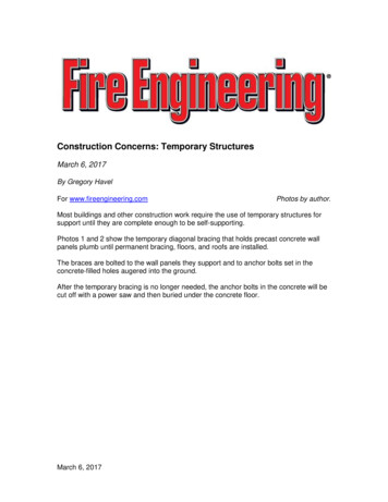
Temporary Traffic Control Guidelinesfor Utility WorkApril, 2016
Table of ContentsNotice of DisclaimerThe North Dakota Department of Transportation (NDDOT)makes the Temporary Traffic Control Guidelines for UtilityWork available on an "as is" basis as a public service.Under no circumstances does NDDOT warrant or certify theinformation to be free of errors or deficiencies of any kind.NDDOT specifically disclaims all warranties, express orimplied, including but not limited to the warranties ofmerchantability and fitness for a particular purpose.Prepared byNORTH DAKOTA DEPARTMENT OF TRANSPORTATION608 EAST BOULEVARD AVENUEBISMARCK, NORTH DAKOTAdot.nd.govIn cooperation withFEDERAL HIGHWAY ADMINISTRATION2016ETS0416Introduction . . . . . . . . . . . . . . . . . . . . . . . . . . . . . . . . . . . . . . . . . .Definitions . . . . . . . . . . . . . . . . . . . . . . . . . . . . . . . . . . . . . . . . . . .Abbreviations . . . . . . . . . . . . . . . . . . . . . . . . . . . . . . . . . . . . . . . .Traffic Control Devices and Methods . . . . . . . . . . . . . . . . . . . . . .Flagging Procedures. . . . . . . . . . . . . . . . . . . . . . . . . . . . . . . . . . .Minimum Spacing of Advances Warning Signs . . . . . . . . . . . . . .Channelizing Devices . . . . . . . . . . . . . . . . . . . . . . . . . . . . . . . . . .Lighting Devices . . . . . . . . . . . . . . . . . . . . . . . . . . . . . . . . . . . . . .Stopping Sight Distance as a Function of Speed . . . . . . . . . . . . .Components of a Temporary Traffic Control Zone . . . . . . . . . . . .Taper Length Criteria for Work Zones . . . . . . . . . . . . . . . . . . . . . .Types of Tapers and Buffer Spaces . . . . . . . . . . . . . . . . . . . . . . .Typical Application Diagrams . . . . . . . . . . . . . . . . . . . . . . . . . . . .Work Beyond Shoulders . . . . . . . . . . . . . . . . . . . . . . . . . . . . . . . .Work on the Shoulders . . . . . . . . . . . . . . . . . . . . . . . . . . . . . . . . .Short-Duration or Mobile Operation on a Shoulder. . . . . . . . . . . .Shoulder Work With Minor Encroachment . . . . . . . . . . . . . . . . . .Work in Travel Lane on Minor Urban Street(Maintaining Two-Way Traffic) . . . . . . . . . . . . . . . . . . . . . . . . .Lane Closure for Two-Lane Low-Volume Road(Two-Flagger Operation) . . . . . . . . . . . . . . . . . . . . . . . . . . . . .Temporary Street Closure (Not to exceed 20 minutes.) . . . . . . . .Work in Center of Minor Urban Street(Maintaining Two-Way Traffic) . . . . . . . . . . . . . . . . . . . . . . . . .Lane Closure on a Minor Urban Street(No Flagger, Traffic Self-Regulating) . . . . . . . . . . . . . . . . . . . .Lane Closure in Advance of Intersection(Two-Way Stop Control With Work on Major Roadway) . . . . .Lane Closure in Advance of Intersection(Two-Way Stop Control With Work onStop-Controlled Approach) . . . . . . . . . . . . . . . . . . . . . . . . . . .Lane Closure Beyond Intersection(Two-Way Stop Control With Work on Major Roadway) . . . . .Lane Closure Beyond Intersection (Two-Way Stop ControlWith Work on Far Side of Stop Control Approach) . . . . . . . . .Closure in Center of Intersection. . . . . . . . . . . . . . . . . . . . . . . . . .Center Turn Lane Closure on a Three-Lane, Two-Way Road. . . .Lane Shift on a Three-LaneTwo-Way Road . . . . . . . . . . . . . . . . .Four-Lane Divided Highway Traffic Control DevicePlacement Work Area in Median . . . . . . . . . . . . . . . . . . . . . . .Lane Closure on Divided Highway . . . . . . . . . . . . . . . . . . . . . . . .Right-Hand Lane Closure on the Far Side of an Intersection . . . .Half-Road Closure on the Far Side of an Intersection . . . . . . . . .Crosswalk Closures and Pedestrian Detours . . . . . . . . . . . . . . . .Sidewalk Detour or Diversion . . . . . . . . . . . . . . . . . . . . . . . . . . . .Temporary Curb Ramps . . . . . . . . . . . . . . . . . . . . . . . . . . . . . . . .Best Practice Recommendations . . . . . . . . . . . . . . . . . . . . . . . . .Contact Information. . . . . . . . . . . . . . . . . . . . . . . . . . . . . . . . . . . .Standard Signs . . . . . . . . . . . . . . . . . . . . . . . . . . . . . . . . . . . . . . 2829303132333334
1IntroductionUtility work and maintenance operations within public right-ofway require careful consideration of the orderly flow ofvehicular and pedestrian traffic. These circumstances meritconsideration since the resulting traffic is not typical of thenormal pattern. The motorists should be sufficiently warned intime to think, react, and be guided around the work area while aflow of traffic is maintained.This handbook serves to provide minimum guidelines oftemporary traffic control (TTC) for utility work. Certain casesmay require more TTC than what is provided here. If questionsarise contact the district office. Also, use the most recent issuefor all referenced technical manuals, current Utility OccupancyApplication and Permit, and NDDOT specification; includinginterim publications unless otherwise approved by the NDDOT.An emergency situation may arise where immediate action toprotect the safety of the general public requires work to bedone on a street or highway where full compliance with theprovisions of this handbook cannot be immediately provided.Nothing in this handbook will be interpreted as requiring aperson or agency to delay such immediate action.All traffic control and warning devices are to meet standards setforth in the current edition of the Manual on Uniform TrafficControl Devices (MUTCD) as approved by the FederalHighway Administration. This manual is based on MUTCD2009 edition and future revisions to the MUTCD may invalidatethis handbook.The on-site supervisor has direct responsibility to ensure thatmotorists and pedestrians are adequately warned.Furthermore, the supervisor will take any necessary actions,such as requesting law enforcement assistance when safetyand orderly traffic flow are jeopardized.(This page intentionally left blank.)1
2DefinitionsThe following definitions apply to this handbook.Activity Area—Temporary traffic control zone area where the workactually takes place. It consists of the work space, traffic space andone or more buffer spaces. (See page 8.)Advanced Warning Area—Temporary traffic control zone areabetween the first warning sign and the transition area; tells trafficwhat to expect ahead. (See page 8.)Arrow Boards—A sign with a matrix of elements capable of eitherflashing or sequential displays. This sign shall provide additionalwarning and directional information to assist in merging andcontrolling road users through or around a TTC zone.Barricade—A portable device used to control road users byclosing, restricting, or delineating all or a portion of the right-of-way.Barricades are classified as Type 1, Type 2, or Type 3 and shallconform in according to Section 6F in MUTCD.Buffer Space—Longitudinal and lateral space which provides amargin of safety for both the driver and the workers. It is importantthat the buffer space be free of equipment, workers, material andvehicles. (See page 8.)Clear Zone—The total roadside border area, starting at the edge ofthe traveled way, that is available for an errant driver to stop orregain control of a vehicle. This area might consist of a shoulder, arecoverable slope, and/or a non-recoverable, traversable slopewith a clear run-out area at its toe.Cone—A traffic channelizing device used to guide the motoristaround the work area; minimum of 28-inch cones are required.Crashworthy—A characteristic of a roadside appurtenance thathas been successfully crash tested in accordance with a nationalstandard either the National Cooperative Highway ResearchProgram (NCHRP) Report 350, "Recommended Procedures forthe Safety Performance Evaluation of Highway Features" orManual for Assessing Safety Hardware (MASH).Drum—A traffic channelizing device constructed of lightweight,deformable materials. (See page 5.)High-Level Warning Device—A device used to supplement othertraffic control measures, by providing additional notice to themotorist. The device consists of a minimum of two flags with orwithout flashing warning lights attached to a warning sign. Theheight of the lowest tip of the flag and/or light shall be at least 8 feet.2Definitions (cont.)Low-Volume Street or Highway—Any street or highway with anAnnual Daily Traffic (ADT) of 400 vehicles per day or less. This datais available from the NDDOT.Reflectorization—Requires that signs shall be reflectorized toshow the same shape and color both day and night.Retroreflectorization—Takes place when light is returned.Specifically the retroreflective properties of traffic signs cause thelight from vehicle headlights to be redirected back to the vehicle,thereby making the traffic sign visible to the driver at night.Termination Area—Traffic Control Zone area located beyond theactivity or work area; allows motorists to resume normal driving.(See page 8.)Traffic Control Zone—Area located between the first advancewarning sign and the end of the termination area.Transition Area—Traffic Control Zone area between the advancewarning area and buffer space; allows traffic to move out of itsnormal path. (See page 8.)AbbreviationsADT—Average Daily TrafficMUTCD—Manual on Uniform Traffic Control DevicesTTC—Temporary Traffic Control
3Traffic Control Devices and MethodsGeneral InformationAll traffic control devices shall be in place before any workbegins. All traffic control devices shall be removed as soon aspractical when they are no longer needed. When work issuspended for short periods of time, traffic control devices thatare no longer appropriate shall be removed or covered. Trafficcontrol devices shall be placed in a traffic lane only when thelane is to be fully or partially blocked.A work site where the motorist's view is limited by physicalobjects, such as hills, curves, side roads, etc., requireadditional warning devices or flaggers.A motor vehicle such as a truck may be used as a buffer tooncoming traffic. Emergency flashers and other warning lightson the vehicle may be used to alert motorists. However, anyvehicle used as a buffer shall be regarded as a supplement, nota substitute, for appropriate warning and traffic control devicespreceding the vehicle. Permission must be obtained if the useof a vehicle as a buffer violates any local governmentordinance.4. Short duration is work that occupies a location up to onehour.5. Mobile is work that moves intermittently or continuously.Note: TTC for Long-term stationary utility-work operation mayneed additional TTC devices or new TTC layout.Consult with the district for your TTC plan.FlaggersTo help control traffic flow around the work area, flaggers arerequired when lane closures cause two directions of traffic tooccupy the same lane. Flaggers should be knowledgeable inflagging operations and have passed the written examinationfound at http://www.ndflaggertraining.com. A uniformed lawenforcement officer may be used in lieu of a flagger.Night OperationsNight work uses combination of flashing arrow panels,barricades with warning lights and other recommendedMUTCD nighttime TTC devices. All traffic control devices mustbe visible to the motorist by either being illuminated orretroreflectorized.If pedestrians are subject to entering the work area, propercontrols and warning devices for pedestrians are to be used.Also, pedestrian pathways shall be maintained at all times. Ifclosed, facilitate easy detour that conforms with AmericansWith Disabilities Act (ADA) guidelines for both temporarysidewalks and ramps or use the standard shown in this book.Pedestrians shall be protected from all hazards.All traffic control devices shall be appropriately maintained. Ifdefective devices are encountered, they should be correctedimmediately and documented.Work DurationHigh-Visibility ClothingDefinitions of five categories of work durations used in thishandbook:All workers who are exposed to traffic, work vehicles orconstruction equipment within the TTC zone are required towear retroreflective clothing in accordance with ANSI/ISEA107, Performance Class 2 or Class 3 requirements.1. Long-term stationary is work that occupies a locationmore than three days.Maintenance2. Intermediate-term stationary is work that occupies alocation more than one daylight period up to three days, ornighttime work lasting more than one hour.Ensure that retroreflective clothing is the outermost garment, ina clean condition, and closed in both the front and rear.Replace retroreflective clothing as necessary to maintainvisibility and reflectivity.3. Short-term stationary is daytime work that occupies alocation for more than one hour within a single daylightperiod.During times of low visibility, require all workers to wear Class 3retroreflective clothing.3
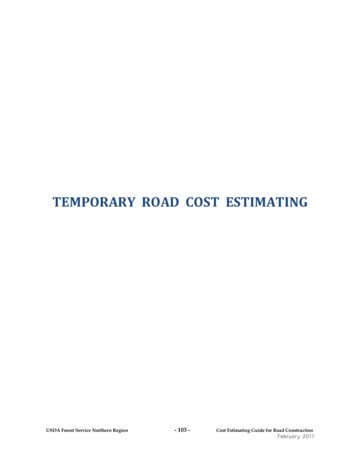
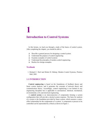
4Flagging Procedures18 inchesMIN.Minimum Spacing of AdvancedWarning SignsADVANCED WARNING SIGN SPACINGR1-1Properly Trained FlaggersŸ Clear message to drivers asshownŸ Allows distance for drivers to reactŸ Coordinate with other flaggersW20-8Properly Equipped FlaggersŸ Approved sign paddlesŸ Approved safety vestŸ Reflective night equipmentŸ Approved hard hatRoad TypeDistance Between SignsMin. (ft.)*ABCUrban - Low Speed(30 mph or less)150150150Urban - Low Speed(over 30 to 40 mph)280280280Urban - High Speed(over 40 to 50 mph)360360360Rural - High Speed(over 50 to 65 mph)720720720Urban Expressway andFreeway (55 to 60 mph)8501,3502,200Rural Expressway andFreeway (70 to 75 mph)1,0001,5002,6407501,0001,500Interstate/4-Lane Divided(Maint. and Surveying)* The column headings A, B, and C are the dimensions between AdvancedW20-8Proper Flagging StationsŸ Good approach sight distanceŸ Highly visible to trafficŸ Never stand in moving traffic laneŸ Stand in a location that enablesescape from errant vehiclesProper Advance Warning SignsŸ Always use warning signsŸ Allow reaction distance from signsŸ Remove signs if not flaggingWarning Signs. The A dimension is the distance from the transition or point ofrestriction to the first sign. The B dimension is the distance between the firstand secondsigns. The C dimension is the distance between the second and*third signs. (The "first sign" is the sign in a three-sign series that is closest tothe TTC zone. The "third sign" is the sign that is furthest from the TTC zone.)Warning Signs—Construction and maintenance warning signsare used extensively in street and highway work zones. As ageneral rule, these signs are located on the right-hand side of thestreet or highway.Size—Required standard size for advance warning sings in workzone is 48 inches by 48 inches. (see Part 6 of the MUTCD foradditional information).Mounting—Standards for height and lateral clearance of roadsidesigns are included in Part 6 of the MUTCD. Signs mounted onbarricades or temporary supports may be at lower heights, but thebottom of the sign shall not be less than one foot above thepavement elevation.Retroreflectivity and Illumination—All signs shall be retroreflective or illuminated to show the same shape and similar color by bothday and night. The requirement for sign illumination shall not beconsidered to be satisfied by street or highway lighting. Specificminimum requirements can be found in Part 2 of the MUTCD.4
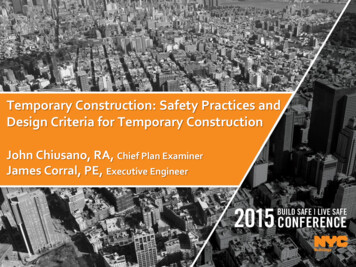
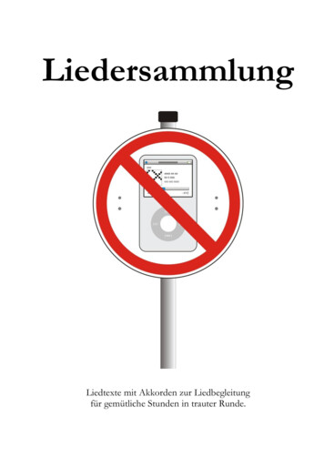
1614Channelizing Devices5Channelizing Devices (cont.)RetroreflectiveBand18 in. MIN.FacingTraffic*4 to 6 in.More than36 in.28 in. MIN. to36 in. MAX.4 to 6 in.3 to 4 in.6 in.2 in.4 in.36 in. MIN.Night and/or FreewayHigh-Speed Roadway( 45 mph)CONESDRUM* * Warning lights (optional)RetroreflectiveBand2 in.3 in.2 to 6 in.3 in.28 in. MIN.*RetroreflectiveBand45 o2 in.24 in. MIN.36 in. MIN.8 to 12 in.3 in.18 in. MIN.TYPE I BARRICADE***45 o636 in. MIN.8 to 12 in.4or*24 in. MIN.4or6in.8 to 12 in.in.Night and/or freewayDay and low-speedhigh-speed roadwayroadway ( 40 mph)( 40 mph)TUBULAR MARKERS24 in. MIN.45 TYPE II BARRICADE**36 in. MIN.12 in. MAX.VERTICAL PANEL* Warning lights (optional)5* Warning lights (optional)** Rail*stripe widths shall be 6 inches, with the exception that 4 inch widestripes may be used if rail lengths are less than 36 inches. The sides ofbarricades facing traffic shall have retroreflective rail faces.
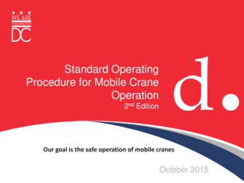
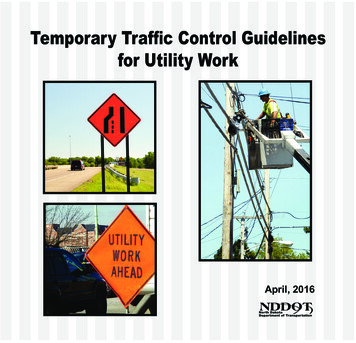
1614Channelizing Devices (cont.)*Lighting DevicesLighting devices for short term utility and maintenance workzones are designed to supplement the signs and channelizingdevices used in these zones. Typical lighting devices includewarning lights, flashing vehicle lights, and flashing arrowpanels.45 oWarning Lights—Warning lights may be used to supplementretroreflectorized signs, barriers, and channelizing devices.The principal types and use of warning lights are:5 ft. MIN.8 to 12 in.4 ft. MIN.1. Low Intensity Flashing Lights (Type A) – Used to warn of anisolated hazard at night. Normally mounted on barricadesand drums.2. High Intensity Flashing Lights (Type B) – Normally mountedon advanced warning signs to draw attention to a hazardboth day and night.TYPE III BARRICADE**3. Steady-Burn Lights (Type C) and 360-degree Steady-BurnLights (Type D) – Used in a series to delineate the edge ofthe traveled way and channelize traffic at night. When usedto delineate a curve, Type C and Type D warning lightsshould only be used on devices on the outside of the curve.24 in.*12 in.36 in.8 in.45 oDIRECTION INDICATOR BARRICADE*** Warning lights (optional)** Rail stripe widths shall be 6 inches, with the exception that 4 inch widestripes may be used if rail lengths are less than 36 inches.The sides ofbarricades facing traffic shall have retroreflective rail faces.66Floodlights—When nighttime work is being performed,floodlights should be used to illuminate the work area. Exceptin emergency situations, flagger stations shall be illuminated atnight.Floodlighting shall not produce a disabling glare condition forapproaching road users, flaggers, or workers. Desiredillumination levels vary depending upon the nature of taskinvolved. An average horizontal luminance of 5 foot candlescan be adequate for general activities. Tasks requiring highlevels of precision and extreme care can require an averagehorizontal luminance of 20 foot candles.
1614Stopping Sight Distanceas a Function of SpeedSpeed*Distance20 mph25 mph30 mph35 mph40 mph45 mph50 mph55 mph115 feet155 feet200 feet250 feet305 feet360 feet425 feet495 feet60 mph65 mph70 mph75 mph570 feet645 feet730 feet820 feet* Posted speed limit.(This page intentionally left blank.)77
16148Taper Length Criteriafor Work ZonesComponents of a TemporaryTraffic Control ZoneThe temporary traffic control zone is the distance between thefirst advance warning sign and the point beyond the work areawhere traffic is no longer affected. Below is a diagram showingthe four parts of a temporary traffic control zone.LEGENDDirection of travelChannelizing deviceWork SpaceSignDownstream TaperBuffer Space(longitudinal)Traffic Spaceallows trafficto passthrough theactivity areaBuffer Space(lateral)providesprotection fortraffic andworkersThere are five types of tapers used in work zone traffic control.The length of each type of taper is based on formulas using thespeed of the traffic and the width of the offset. The following arethe five types of tapers and their lengths.TAPER LENGTH CRITERIA FOR TEMPORARYTRAFFIC CONTROL ZONESTermination Arealets traffic resumenormal operationsType of TaperMerging TaperTaper Length (L)Shifting TaperShoulder Taperat least 0.5Lat least 0.33L50 ft. min.100 ft. max.50 ft. min.,100 ft. max.per laneOne-Lane, Two-Way Traffic TaperDownstream TaperWork Space isset aside forworkers, equipment,and material storageActivity Areais where worktakes placeBuffer Space(longitudinal)provides protection fortraffic and workersTransition Areamoves trafficout of itsnormal pathShoulder TaperAdvanceWarning Areatells trafficwhat to expectaheadTABLE FOR TAPER LENGTHSSpeed LimitMPH*1515202530354045505560657075Taper Lengths (L), ft.12 f t.* *4580125125180180245320540600660720780840900* Posted speed limit.** Width of offset.8at least L11 f t.* *417311511516516522529349555060566071571577082510 f t.* *3867104104150150204267450500550600650700750
1614Types of Tapers and Buffer SpacesLEGENDDirection of travelChannelizing deviceWork SpaceSignMergingTaper9Typical Application DiagramsThe diagrams on the following pages represent examples ofthe application of principles and procedures for safe andefficient traffic control in work zones, but are not intended to bestandards. It is not possible to include illustrations to coverevery situation which will require work area protection. Thesetypical temporary traffic control layouts are not intended as asubstitute for engineering judgement and should be altered tofit the conditions of a particular site.LegendLArrow panelArrow panel support or trailer(shown facing down)Channelizing deviceShifting 1/2 LTaperDownstreamTaper(optional)Direction of trafficFlaggerLateral BufferSpace(optional)Shifting1/2 LTaperLongitudinalBuffer Space(optional)1/2 LShiftingTaperHigh level warning device(flag tree)Sign (shown facing left)Surveyor4S ft*Truck-mounted attenuator (TMA)LongitudinalBuffer Space(optional)1/3 L ShoulderTaperType III barricadeWarning lightsWork space*S speed in mph9Work vehicle
1614Work Beyond Shoulders10Notes for Work Beyond Shoulders TTC Layout:1. The UTILITY WORK AHEAD sign may be omitted where thework space is behind a barrier, more than two feet behindthe curb, or 15 feet or more from the edge of the roadway.2. The UTILITY WORK AHEAD sign may be replaced with theROAD WORK AHEAD sign or the SHOULDER WORKAHEAD sign.3. Where the activity is spread out over a distance of morethan two miles, place advance warning sign every one mile.4. An advance warning sign shall be used if the work will beperformed immediately adjacent to the shoulder, ifequipment will cross or move along the roadway, or if theactivity may distract motorists.5. For short-term, short-duration, or mobile operation; all signsand channelizing devices may be eliminated if a vehicle withactivated high-intensity rotating, flashing, oscillating, orstrobe lights are used.A10
1614Work on the Shoulders11Notes for Work on the Shoulders TTC Layout:1. UTILITY WORK AHEAD sign may be used instead ofSHOULDER WORK sign.2. For short duration operations of 60 minutes or less, all signsand channelizing devices may be eliminated if a vehicle withactivated high-intensity rotating, flashing, oscillating, orstrobe lights is used.3. Vehicle hazard warning signals may be used to supplementhigh-intensity rotating, flashing, oscillating, or strobe lights.SHOULDER1/3 LASHOULDERSHOULDERASHOULDER1/3 L1/3 LASHOULDERB11
1614Short-Duration or MobileOperation on a Shoulder12Notes for Short-Duration or Mobile Operation on aShoulder TTC Layout:1. In situations where multiple work locations within a limiteddistance make it practical to place stationary signs, thedistance between the advance warning sign and the workshould not exceed three miles.2. Stationary warning signs may be omitted for short durationor mobile operations if the work vehicle displays highintensity rotating, flashing, oscillating, or strobe lights.Work Vehicle3. Vehicle hazard warning signals may be used to supplementhigh-intensity rotating, flashing, oscillating, or strobe lights.However, they cannot be used as a warning device.4. The UTILITY WORK AHEAD sign may be used instead ofthe ROAD WORK AHEAD sign.Shadow Vehicle(optional)Truck-Mounted Attenuator(optional)SHOULDERSee Note 1NEXTXX MILES(optional)12
1614Shoulder Work WithMinor Encroachment13Notes for Shoulder Work With Minor Encroachment TCCLayout:1. Where the opposite shoulder is suitable for carryingvehicular traffic and of adequate width, lanes may be shiftedby use of closely-spaced channelizing devices, providedthat the minimum lane width of 10 feet is maintained.2. Additional advance warning may be appropriate, such as aROAD NARROWS sign.3. Temporary traffic barriers may be used along the workspace. All barrier devices, used longitudinally, should meetthe crashworthy requirement. Do not use barriers for amerging taper. (See definition for crashworthy for therequirement.)A4. For short-duration work (less than one hour), the taper andchannelizing devices may be omitted if a shadow vehiclewith activated high-intensity rotating, flashing, oscillating, orstrobe lights is used.Work Vehicle10 ftMINTruck-MountedAttenuator(optional)Buffer Space(optional)1/3 LA13
1614Work in Travel Lane onMinor Urban Street(Maintaining Two-Way Traffic)14Notes for Work in Travel Lane on Minor Urban Street(Maintaining Two-Way Traffic) TCC Layout:1. A minimum lane width of 10 feet should be provided in bothdirections, this lane width should not extend beyond theedge of pavement. Lane width restriction signs may berequired.2. The UTILITY WORK AHEAD sign may be replaced with theROAD WORK AHEAD sign.BA(50 to 100’)1/2 L10’10’Buffer Space(optional)1/2 LAB14
1614Lane Closure for Two-LaneLow-Volume Road(Two-Flagger Operation)15Notes for Lane Closure for Two-Lane Low-Volume Road(Two-Flagger Operation) TTC Layout:1. A single flagger may be adequate for low volumeapplications. Where one flagger is used, such as for shortwork areas on straight roadways, the flagger must be visibleto approaching traffic from both directions.2. UTILITY WORK AHEAD sign may be used in place ofROAD WORK XX FT signs.3. For operations of 60 minutes or less, the ROAD WORK XXFT sign may be omitted.4. In situations where the work zone is on a horizontal or crestvertical curve, extend buffer space so that the two-waytaper is placed before the curve to provide adequatestopping sight distance for the flagger and a queue ofstopped vehicles.(50 to 100’)See Note 5One Lane Two-Way Traffic Taper(50 to 100’)A(optional)BC15
1614Temporary Street Closure(Not to exceed 20 minutes.)16Notes for Temporary Street Closure (Not to exceed 20minutes.) TCC Layout:1. Conditions represented are for work which requires closureduring daytime hours only.2. This application is intended for a planned temporary closurenot to exceed 20 minutes on low speed streets.(optional)C3. UTILITY WORK AHEAD signs may be used in place ofROAD WORK AHEAD BBEPREPAREDTO STOPC16(optional)
1614Work in Center of Minor Urban Street(Maintaining Two-Way Traffic)17Notes for Work in Center of Minor Urban Street(Maintaining Two-Way Traffic) TTC Layout:1. A minimum lane width of 10 feet should be provided in bothdirections as measured from the channelizing devises tothe edge of pavement.2. The KEEP RIGHT symbol signs (R4-7) may be replacedwith the KEEP RIGHT with arrow signs (R4-7a).3. ROAD WORK AHEAD signs may be used in place ofUTILITY WORK AHEAD signs.A1/2 L(optional)(optional)1/2 L(10’ ) minimum toedge of pavementor outside edge ofpaved shoulderA17
1614Lane Closure on a Minor Urban Street(No Flagger, Traffic Self-Regulating)18Notes for Lane Closure on a Minor Urban Street (NoFlagger, Traffic Self-Regulating) TTC Layout:1. This layout is only appropriate for low-volume, low-speed(30 mph or less) streets, such as local residential streets.2. This procedure is not to be used in rural areas.3. Traffic can regulate itself while volumes are low and thelength of the work space is short, thus allowing traffic toreadily see the roadway beyond.A4. Where traffic does not self-regulate effectively, use twoflagger operation in the layout on page 15.5. A ROAD WORK AHEAD sign may be used in place ofWORKER sign (W21-1).Work Buffer Space(optional)(50 to 100’)A18
1614Lane Closure in Advance of Intersection(Two-Way Stop Control With Workon Major Roadway)Notes for Lane Closure in Advance of Intersection(Two-Way Stop Control With Work on Major Roadway) TTCLayout:1. Depending on traffic conditions, additional traffic control,such as flaggers and appropriate signage, may be neededon the cross road approaches.2. ROAD WORK AHEAD signs may be used in place ofUTILITY WORK AHEAD signs.CBABuffer Space(optional)(50 to 100’)ABC1919
1614Lane Closure in Advance of Intersection(Two-Way Stop Control With Work onStop-Controlled Approach)20Notes for Lane Closure in Advance of Intersection (TwoWay Stop Control With Work on Stop-ControlledApproach) TTC Layout:1. Depending on traffic conditions, additional traffic control,such as flaggers and appropriate signage, may be neededon the cross road approaches.2. ROAD WORK AHEAD signs may be used in place ofUTILITY WORK AHEAD signs.AAABBuffer Space(optional)(50 to 100’)ABC20B
1614Lane Closure Beyond Intersection(Two-Way Stop Control With Work onMajor Roadway)Notes for Lane Closure Beyond Intersection (Two-WayStop control With Work on Major Roadway) TTC Layout:1. Depending on traffic conditions, additional traffic control,such as flaggers and appropriate signage, may be neededon the cross road approaches.2. ROAD WORK AHEAD signs may be used in place ofUTILITY WORK AHEAD signs.CBA(200 to 300’)(100’)Buffer Space(optional)(50(100’)to 100’)MAX.AAABC2121
1614Lane Closure Beyond Intersection(Two-Way Stop Control With Work onFar Side of Stop Control Approach)CA(200 to 300’)(100’)Buffer Space(optional)(50 to 100’)BAAABC22Notes for Lane Closure Beyond Intersection (Two-WayStop Control With Work on Far Side of Stop ControlApproach) TTC Layout:1. Depending on traffic conditions, additional traffic control,such as flaggers and appropriate signage, may be neededon the cross road approaches.2. ROAD WORK AHEAD signs may be used in place ofUTILITY WORK AHEAD signs.BB22
1614Closure in Center of Intersection23Notes for Closure in Center of Intersection TTC Layout:1. Prohibit left turns as required by traffic conditions. Unlessthe streets are wide, it may be physically impossible to turnleft, especially for large vehicles.2. A minimum of six channelizing devices shall be used foreach taper.3. For operations 20 minutes or less in duration, thechannelizing devices may be eliminated if a flashing orrevolving yellow light is displayed in the work space.A4. A high-level warning device should be placed in th
Road Type Distance Between Signs Min. (ft.)* Urban - Low Speed (30 mph or less) Urban - Low Speed (over 30 to 40 mph) Urban - High Speed (over 40 to 50 mph) Rural - High Speed (over 50 to 65 mph) Urban Expressway and Freeway (55 to 60 mph) Rural Expressway and Freeway (70 to 75 mph) Interstate/4-Lane Divided (Maint. and Surveying) A B C 150 150 .