Transcription
U.S. Department of Housing and Urban DevelopmentOffice of Policy Development and ResearchPrescriptive Method for ConnectingCold-Formed Steel Framing toInsulating Concrete Form Wallsin Residential Construction
PATH (Partnership for Advancing Technology in Housing) is a new private/public effortto develop, demonstrate, and gain widespread market acceptance for the “NextGeneration” of American housing. Through the use of new or innovative technologies,the goal of PATH is to improve the quality, durability, environmental efficiency, andaffordability of tomorrow’s homes.PATH is managed and supported by the U.S. Department of Housing and UrbanDevelopment (HUD). In addition, all federal agencies that engage in housing researchand technology development are PATH Partners, including the Departments of Energy,Commerce, and Agriculture as well as the Environmental Protection Agency (EPA) andthe Federal Emergency Management Agency (FEMA). State and local governments andother participants from the public sector are also partners in PATH. Product manufacturers,home builders, insurance companies, and lenders represent private industry in thePATH Partnership.To learn more about PATH, please contact451 7th Street, SWSuite B 133Washington, DC 20410202-708-5873 (fax)202-708-4277 (phone)e-mail: pathnet@pathnet.orgwebsite: www.pathnet.orgVisit PD&R’s websitewww.huduser.orgto find this report and others sponsored byHUD’s Office of Policy Development and Research (PD&R).Other services of HUD USER, PD&R’s Research Information Service, include listservs;special interest, bimonthly publications (best practices, significant studies from othersources); access to public use databases; and a hotline 1-800-245-2691 for help accessingthe information you need.
Prescriptive Method for ConnectingCold-Formed Steel Framing toInsulating Concrete Form Wallsin Residential ConstructionPrepared for:U.S. Department of Housing and Urban DevelopmentOffice of Policy Development and ResearchWashington, DCThe Steel Framing AllianceWashington, DCThe Portland Cement AssociationSkokie, ILThe Insulating Concrete Form AssociationGlenview, ILPrepared by:Building Works, Inc.Cambridge, MAContract H-21311CAFebruary 2003
DISCLAIMERNeither the U.S. Department of Housing and Urban Development of the U.S. Government,nor the Portland Cement Association, nor the Steel Framing Alliance, nor the InsulatingConcrete Form Association, nor Building Works, Inc., nor its employees or representativesmakes any warranty, guarantee, or representation, expressed or implied, with respectto the accuracy or completeness of information contained in this document or its fitnessfor any particular purpose, or assumes any liability for damages or injury resulting fromthe applications of such information. Users are directed to perform all work in accordancewith applicable building code requirements.NOTICEThe contents of this report are the views of the contractor and do not necessarilyreflect the views or policies of the U.S. Department of Housing and Urban Developmentor the U.S. government. The U.S. government does not endorse products ormanufacturers. Trade or manufacturer names appear herein solely because they areconsidered essential to the object of this report.iv
PrefaceIn recent years construction of single-family homes with exterior walls of insulatingconcrete forms has grown rapidly. The use of cold-formed steel for the construction ofresidential interior walls, floors, and roofs has likewise grown rapidly. The reasonsgiven for use of both materials include: DurabilityStrengthMaterial consistencyPrice stability of materialEcological concernsYet builders who have combined insulating concrete forms and cold-formed steel framingin homes complain of a lack of information on making the connections. Many say thatthey believe they are employing overly involved and expensive methods. However,they are unwilling to employ simpler methods for fear that the connections might beinadequate.This publication is intended to alleviate these problems by providing construction detailsand schedules for the connection of cold-formed steel frame walls, floor decks, androofs to insulating concrete form exterior walls, based on engineering analysis andcommon building requirements. It is also intended to provide code officials and inspectorswith the guidance necessary to perform their duties in home construction when thesematerials are used. Note that this publication is intended for use only by qualifiedindustry professionals who can evaluate the applicability of its recommended details inspecific projects and circumstances.By facilitating the construction of houses from insulating concrete forms and coldformed steel, HUD expands housing affordability and quality through competition fromnew methods and materials.v
vi
AcknowledgmentsThis publication was produced under contract to the U.S. Department of Housing andUrban Development, the Steel Framing Alliance, the Insulating Concrete Form Association,and the Portland Cement Association. It was researched and developed at BuildingWorks, Inc. Ivan S. Panushev, supervised all engineering and technical content, andPieter A. VanderWerf, Ph.D., provided guidance and general project management.This book is the third publication in a prescriptive method series produced by the U.S.Department of Housing and Urban Development on insulating concrete forms and coldformed steel framing. We would like to thank all individuals involved in preparing thosepublications on which Chapters 2 and 3 are largely based.Special appreciation for review and supervision is extended to the members of thesteering committee:Karen Bexten, P.E., Tadros Associates, LLC.Kevin Bielat, American Iron and Steel InstituteWilliam Freeborne, P.E., U.S. Department of Housing and Urban DevelopmentJonathan Humble, A.I.A., American Iron and Steel InstituteWilliam Oliver, WMWN, Inc.Daniel Peterson, PK ConstructionDavid Shepherd, A.I.A., Portland Cement AssociationAndrea Vrankar, P.E., R.A, U.S. Department of Housing and Urban DevelopmentTimothy Waite, P.E., Steel Framing AllianceThe authors gratefully acknowledge the assistance of the following individuals andorganizations:Bill Kraft, Steel Framing AllianceAmerican Polysteel Forms, Inc.Nader Elhajj, P.E., NAHB ResearchCenter, Inc.Amvic Building Systems, Inc.Vern Jones, Intertek TestingServicesARXX Building Products, Inc.Roger Laboube, Ph.D., Universityof Missouri - RollaJay Larson, P.E., Bethlehem SteelCo.Architectural/Residential Technologies, Inc.Bailey Metal Products, Ltd.Construction Technologies Laboratories, Inc.Dietrich Metal Framing, Inc.Insul-Deck, Inc.Paul Lynch, Fairfax County, VirginiaIntertek Testing ServicesTeoman Pekoz, Ph.D., CornellUniversityLite-Form Technologies, Inc.Larry Williams, Light-Gauge SteelEngineers AssociationQuad-Lock, IncNUCONSTEEL, Co.Reward Wall Systems, Inc.Simpson Strong-Tie Co., Inc.vii
viii
Table of ContentsPreface . vAcknowledgements . viiExecutive Summary . xvChapter 1: Introduction . 1Chapter 2: General . 3Purpose . 3Approach . 3Scope . 3Definitions . 7Chapter 3: Materials, Shapes, and Standard Sizes . 15Insulating Concrete Forms . 15Flat ICF Wall Systems . 16Waffle-Grid ICF Wall Systems . 16Screen-Grid ICF Wall Systems . 16Form Materials . 17Concrete Materials. 17Concrete Mix . 17Compressive Strength . 18Reinforcing Steel . 18Cold-Formed Steel . 18Material . 18Corrosion Protection . 18Member Designation . 19Physical Dimensions . 20Base Metal Thickness . 22Bend Radius . 22Yield Strength . 22Product Identification . 23Performance of Steel in Homes. 23Galvanized Steel in Contact With Building Materials . 23Bearing Stiffeners . 24Clip Angles . 24Fasteners . 24Drive Pins and Nails . 31Bolts . 31ix
Chapter 4: ICF-to-Steel Floor Connection Methods . 33Introduction . 33Applicability Limits . 33Floor Connection Requirements . 34Anchor Bolt . 34Right Angle Steel Plate . 36Connection at End Floor Joist . 37Steel-and-Concrete Floors . 41Concrete - Topped Steel Deck . 41Foam/CFS Concrete Form Deck . 42CFS Joist/Concrete Composite . 43Chapter 5: ICF-to-Steel Non-Structural Wall Connection Methods . 45Introduction . 45Applicability Limits . 46Basic Interior Wall Requirements . 46Construction Details . 46Chapter 6: ICF-to-Steel Exterior Wall Connection Methods . 49Introduction . 49Applicability Limits . 49Exterior Wall Connection Requirements . 50Direct Track to ICF Wall Connection . 50Track to ICF Wall Connection with Wood Sill and Steel Plate . 51Track to ICF Wall Connection with Wood Sill and Uplift Strap . 52Chapter 7: ICF-to-Steel Roof Connection Methods . 57Introduction . 57Applicability Limits . 57Basic Roof Connection Requirements . 58Top Plate Connected to ICF Wall With Concrete Anchor Steel Straps . 58Embedded Steel Strap . 60Right-Angle Steel Strap With Epoxy Anchor Bolt . 62Chapter 8: References . 67Appendix, Metric Conversion . 71x
List of TablesTABLE 2.1 APPLICABILITY LIMITS . 5TABLE 2.2 EQUIVALENT BASIC WIND SPEEDS . 14TABLE 3.1 DIMENSIONAL REQUIREMENTS FOR CORES AND WEBS IN WAFFLE- ANDSCREEN- GRID ICF WALLS . 16TABLE 3.2 COLD-FORMED STEEL MEMBER SIZES . 20TABLE 3.3 MINIMUM THICKNESS OF COLD-FORMED STEEL MEMBERS . 22TABLE 3.4 MINIMUM COATING REQUIREMENTS . 23TABLE 3.5 SCREW BODY DIAMETER . 26TABLE 3.6 SCREW SUBSTITUTION FACTOR . 30TABLE 4.1 LATERAL VELOCITY PRESSURE FOR DETERMINATION OFICF-TO-FLOOR CONNECTION REQUIREMENTS . 38TABLE 4.2 MAXIMUM CONNECTOR SPACING AT STEEL LEDGER TRACK TO ICFWALL CONNECTION . 39TABLE 4.3 ADDITIONAL CAPACITY REQUIRED (PLF) FOR LEDGER TRACK TO ICFWALL CONNECTION IN DESIGN CATEGORIES C, D1 AND D2 . 40TABLE 4.4 MINIMUM NUMBER OF ANCHOR BOLTS REQUIRED ALONG END FLOORJOIST TO ICF SIDE WALL CONNECTION . 40TABLE 6.1 LATERAL WIND VELOCITY PRESSURE FOR DETERMINATION OF ICF-TOEXTERIOR STEEL WALL CONNECTION REQUIREMENTS . 53TABLE 6.2 BASIC ICF-TO-EXTERIOR STEEL WALL CONNECTION REQUIREMENTS . 53TABLE 6.3 ICF-TO-EXTERIOR STEEL WALL UPLIFT CONNECTION CAPACITY ATEACH FRAMING MEMBER . 54TABLE 6.4 TOTAL NUMBER OF NO. 8 SCREWS IN FLANGES OF WALL STUD TOSTEEL STRAP CONNECTION . 55TABLE 7.1 LATERAL WIND VELOCITY PRESSURE FOR DETERMINATION OF ICF-TOSTEEL ROOF CONNECTION REQUIREMENTS . 63xi
TABLE 7.2 CONCRETE ANCHOR STEEL STRAP SPACING TO CONNECT SILL PLATETO ICF WALL . 64TABLE 7.3 ROOF FRAME TO SILL PLATE REQUIRED UPLIFT CONNECTION CAPACITY . 64TABLE 7.4 FASTENER SCHEDULE FOR STEEL STRAPS AT ICF WALL PARALLEL TORIDGE . 65TABLE 7.5 STEEL STRAP SPACING TO CONNECT END ROOF TRUSS OR JOIST TOICF WALL PERPENDICULAR TO RIDGE . 66xii
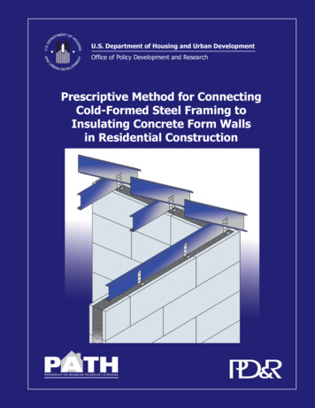
List of FiguresFigure 2.1.Insulating Concrete Form (ICF) Systems . 6Figure 3.1.Flat ICF Wall Systems . 15Figure 3.2.Waffle-Grid ICF Wall Systems . 17Figure 3.3.Screen-Grid ICF Wall Systems . 17Figure 3.4.Track Section Dimensions . 21Figure 3.5.C-Shape Section Dimensions . 21Figure 3.6.Screw Point Type . 25Figure 3.7.Screw Length Measurements . 26Figure 3.8.Screw Grip Range . 27Figure 3.9.Screw Head Types . 28Figure 3.10. Screw Drive Types . 29Figure 3.11 Floor Sheathing-to-Steel Connection . 29Figure 3.12. Steel-to-Steel Screw Connection . 30Figure 4.1.Anchor Bolt to Ledger Track Connection . 35Figure 4.2.Right Angle Plate to Ledger Track Connection . 36Figure 4.3.Connection at End Floor Joist . 37Figure 4.4-A. Concrete-topped Steel Deck . 42Figure 4.4-B. Foam/CFS Concrete Form Deck . 43Figure 4.4-C. CFS Joist/Concrete Composite . 44Figure 5.1.Typical ICF-to-Light Gauge Steel Wall Connection Details . 47Figure 6.1.Direct Track to ICF Wall Connection . 50Figure 6.2.Track to ICF Wall Connection with Wood Sill and Steel Plate . 51Figure 6.3.Track to ICF Wall Connection with Wood Sill and Uplift Strap . 52Figure 7.1.Steel Concrete Anchor Strap and Sill Plate Connection Methodat Wall Parallel to Ridge . 58Figure 7.2.Steel Concrete Anchor Strap and Sill Plate Connection Methodat Wall Perpendicular to Ridge . 59Figure 7.3.Steel Strap Connection at Wall Parallel to Ridge . 60xiii
xivFigure 7.4.Steel Strap Connection Method at End Roof Joist to WallPerpendicular to Ridge . 61Figure 7.5.Steel Strap Connection With Epoxy Anchor at Wall Parallel to Ridge. 62Figure 7.6.Steel Strap With Epoxy Anchor Connection Method at End Roof Joistto Wall Perpendicular to Ridge . 63
Executive SummaryThe Prescriptive Method for Connecting Cold-Formed Steel Framing to Insulating ConcreteForm Walls in Residential Construction was developed as a guideline for the connectionof cold-formed steel (CFS) frame assemblies and structures to insulating concrete form(ICF) exterior walls in the construction of single-family homes. These guidelines areonly intended to apply subject to the limitation presented in Chapter 2. They areintended for use only by qualified industry professionals who can evaluate theirapplicability in specific projects and circumstances.The common connections between cold-formed steel framing and insulating concreteform walls are: CFS interior walls to ICF exterior walls; CFS floor decks to ICF exterior walls; CFS roof structures to ICF exterior walls; and Upper-story CFS exterior walls to lower-story ICF exterior walls.For each connection there are alternative connection methods that are believed to beeconomical and reliable. The chapters that follow contain recommended specificationsfor such connections.Non-loadbearing interior CFS walls in many cases require no connection to the ICFexterior wall. Where the interior wall will be subject to high lateral forces or vibrations,a simple fastener to the ICF wall or to some form of plate fastened to the ties isrecommended.CFS floor decks include ledger tracks to which the joists are fastened. These ledgertracks may be fastened to the ICF exterior wall by means of anchor bolts or right angleledger connectors. Within specified limits, the joists may be fastened to the tracksdirectly by means of self-tapping sheet metal screws.The end joists of CFS floor decks are to be attached to the side walls of the building.This may be accomplished by means of anchor bolts.In addition to floor decks consisting of CFS joists and plywood or OSB sheathing, thereare several floor systems that create floor decks entirely of steel and concrete components.This document provides general descriptive information regarding several such systems.CFS roof members (trusses or joists and rafters) may be connected to the ICF wallsdirectly by means of embedded steel straps. Alternatively, they may be connected to atop plate by means of steel connection plates, and the plate connected to the ICF wallsby means of embedded steel straps. As a third alternative, roofing members may beconnected to the ICF wall directly be means of anchor bolts adhered into special holesdrilled in the concrete after the concrete has cured.The end roof members are to be connected to the ICF side walls at various intermediatexv
points. This may be accomplished by any of the same three methods that the otherroof connections are made.Upper-story CFS exterior walls may be connected to lower-story ICF exterior walls bymeans of anchor bolts through the bottom plate of the CFS wall.xvi
Chapter 1Chapter 1IntroductionThe materials set forth herein are for general information only. They are not asubstitute for competent professional assistance. Application of this information toa specific project or setting should be reviewed by a qualified individual. The authorsbelieve that the information contained in this publication substantially representsindustry practice and related scientific and technical information, but the informationis not intended to represent an official position of any organization or to restrict orexclude any other construction or design technique. Anyone making use of theinformation set forth herein does so at his or her own risk and assumes any resultingliability.Note that references made to other publications are in brackets [ ] throughout thebody of this document. All references can be found in Chapter 8.Prescriptive Method for Connecting Cold-FormedSteel Framing to Insulating Concrete Form Walls1
Chapter 1Prescriptive Method for Connecting Cold-FormedSteel Framing to Insulating Concrete Form Walls2
GeneralGeneralChapter 2Chapter 2PurposeThe purpose of this document is to provide a prescriptive method for the connectionof cold-formed steel framing members and assemblies to exterior walls built ofinsulating concrete forms. These provisions include definitions, connection details,fastener schedules, and other related information appropriate for use by homebuilders,design professionals, and building code officials.ApproachThese requirements are based primarily on the American Iron and Steel Institute’s(AISI) Specification for the Design of Cold-Formed Steel Structural Members [1] forsteel member strength, on the American Concrete Institutes’s (ACI) Building CodeRequirements for Structural Concrete [2], on the Structural Design of InsulatingConcrete Form Walls in Residential Construction [3] for concrete design andspecification, and on the Standard for Cold-Formed Steel Framing - PrescriptiveMethod for One and Two Family Dwellings [29] for steel framing requirements. Theprovisions for building loads are based on the American Society of Civil Engineers’(ASCE) Minimum Design Loads for Buildings and Other Structures [4], theInternational Building Code [5], and the International Residential Code [6].These provisions are intended to represent sound engineering and constructionpractice, taking into account the need for practical and affordable constructiontechniques for residential buildings. This document is not intended to restrict theuse of sound judgment or exact engineering analysis of specific applications.ScopeThe provisions of this Prescriptive Method apply to the construction of detachedone- and two- family dwellings, townhouses, and other attached single-familyPrescriptive Method for Connecting Cold-FormedSteel Framing to Insulating Concrete Form Walls3
Chapter 2dwellings in compliance with the general limitations of Table 2.1. The limitations areintended to define the appropriate use of this document for most one- and twofamily dwellings. Using insulating concrete forms and cold-formed steel systemswith other construction materials in a single structure shall be in accordance withthe applicable building code requirements for that material, the general limitationsof Table 2.1, and relevant provisions of this document. An engineered design shallbe required for applications that do not meet the limitations of Table 2.1.The provisions of the Prescriptive Method shall not apply to irregular structures orportions of structures in Seismic Design Categories C, D1, and D2. Only such irregularportions of structures shall be designed in accordance with accepted engineeringpractice to the extent such irregular features affect the performance of the structure.A portion of the building shall be considered to be irregular when one or more of thefollowing conditions occur: Exterior shear wall lines are not in one plane vertically from thefoundation to the uppermost story in which they are required (i.e., cantilevers).A section of floor or roof is not laterally supported by shear walls on alledges.An opening in the floor or roof exceeds the lesser of 12 ft (3.7 m) or 50percent of the least floor dimension.Portions of the floor are vertically offset.Shear walls (i.e. exterior ICF walls) do not occur in two perpendiculardirections.Shear walls are constructed of dissimilar systems on any one story level.Prescriptive Method for Connecting Cold-FormedSteel Framing to Insulating Concrete Form Walls4
ATTRIBUTEGeneralMAXIMUM LIMITATIONS60 feet with center bearing wall or beam32 feet without center bearing wall or beamNumber of Stories2 stories above grade with a basementDesign Wind Speed130 mph (209 km/h) 3-second gustGround Snow Load70 psf (3.4 kPa)Seismic Design CategoryA, B, C, D1 and D2 (Seismic Zones (0, 1, 2, 3, and4)GeneralBuilding DimensionsChapter 2TABLE 2.1APPLICABILITY LIMITSFloorsFloor Dead Load10 psf (0.72 kPa)First-Floor Live Load40 psf (1.9 kPa)Second-Floor Live Load (sleeping rooms)30 psf (1.4 kPa)Floor Clear Span (unsupported)32 feet (9.8 m)Walls - Concrete3Unit Weight of Concrete150 pcf (23.6 kN/m )Wall Height (unsupported)10 feet (3 m)Walls - Cold-Formed SteelWall Dead Load210 psf (0.48 kN/m )Load Bearing Wall Height10 feet (3 m)Roof and Ceiling Dead Load15 psf (0.72 kPa)Roof Live Load (ground snow load)70 psf (3.4 kPa)Roof Slope3:12 to 12:12Attic Live Load20 psf (0.96 kPa)Roof Clear Span (unsupported)32 feet (9.8 m)RoofsFor SI: 1 foot 0.3048 m; 1psf 47.8804 Pa; 1 pcf 157.0877 N/m3 16.0179 kg/m3; 1 mph 1.6093 km/hrPrescriptive Method for Connecting Cold-FormedSteel Framing to Insulating Concrete Form Walls5
Chapter 2ConcreteFlat ICF Wall SystemSteel ReinforcementInsulating FormWaffle-Grid ICF Wall SystemVertical Concrete CoreHorizontal Concrete CoreInsulating FormVertical Concrete CoreScreen-Grid ICF Wall SystemHorizontal Concrete CoreInsulating FormFigure 2.1. Insulating Concrete Form (ICF) SystemsPrescriptive Method for Connecting Cold-FormedSteel Framing to Insulating Concrete Form Walls6
The following are definitions of key terms as they are used in this document. Figure2.1 illustrates certain terms as referenced by these definitions.Anchor Bolt: A bolt, headed or threaded, used to connect a structural member ofdifferent material to a concrete member.GeneralAccepted Engineering Practice: An engineering approach that conforms withaccepted principles, tests, technical standards, and sound judgment.Chapter 2DefinitionsApproved: Reference to approval by the building code authority having jurisdiction.A rational design by a competent design professional shall constitute grounds forapproval.Attic: The enclosed space between the ceiling joists of the top-most floor and theroof rafters of a building not intended for occupancy but sometimes used for storage.Authority Having Jurisdiction: The organization, political subdivision, office, orindividual charged with the responsibility of administering and enforcing the provisionsof applicable building codes.Axial Load: The longitudinal force acting on a member. Examples are the gravityloads carried by columns or studs.Backfill: The soil that is placed adjacent to completed portions of a below-gradestructure (i.e., basement) with suitable compaction and allowance for settlement.Basement: That portion of a building, which is partly, or completely below gradeand which may be used as habitable space.Bearing Stiffener: Additional material that is attached to the web to strengthenthe member against web crippling. Also called a web stiffener.Bond Beam: A continuous horizontal beam of concrete with steel reinforcementlocated in the exterior walls of a structure to tie the structure together and distributeloads.Buckling: A kink, wrinkle, bulge, or otherwise loss of the original shape of a memberdue to compressive, bending, bearing, or shear loads.Building: Any one- or two-family dwelling or portion thereof that is used for humanPrescriptive Method for Connecting Cold-FormedSteel F
Bailey Metal Products, Ltd. Construction Technologies Laboratories, Inc. Dietrich Metal Framing, Inc. Insul-Deck, Inc. Intertek Testing Services . Typical ICF-to-Light Gauge Steel Wall Connection Details . 47 Figure 6.1. Direct Track to ICF Wall Connection .50 Figure 6.2. Track to ICF Wall Connection with Wood Sill and Steel Plate .