Transcription
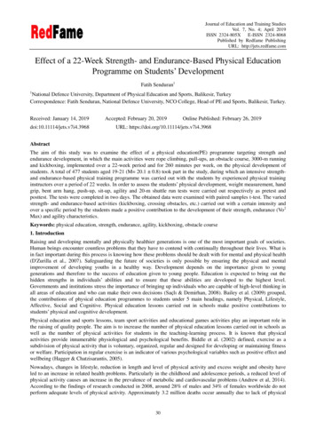
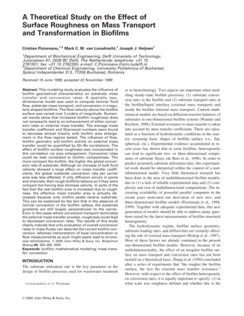
International Journal of Scientific Engineering and Research (IJSER)www.ijser.inISSN (Online): 2347-3878, Impact Factor (2015): 3.791Effect of Length of Boom Support Leg on FreeStanding Jib CraneParag Yawale¹, Prof. Nilesh Khandare²¹ME Student SSGM College of Engineering, Shegaon, India²Assistant Prof. SSGM College of Engineering, Shegaon, IndiaAbstract: Free standing jib cranes are one of the materials handling equipment used intensively. Various design standards areavailable for design of jib crane, which helps designer to choose appropriate design parameters. Numbers of analysis techniques areavailable for design and validation of jib crane elements. In this paper an attempt has been made to optimize the length of boom supportleg of free standing jib crane having capacity of 1Ton. With the help of FEM software i.e. ANSYS 15, by using trial and error method, itis found that, stresses developed in crane were minimum when length of leg boom support equals to near about 1/3rd of column height.Keywords: Jib crane, Boom support leg, ANSYS, Indian Standards, Analysis1. Introduction2. Problem StatementJib cranes are very useful for lifting and transferring heavyloads in circular work volume. Jib crane provides easy, safeand faster transfer of load from one place to another.Standard jib cranes can lift much heavier loads than othersimilar material handling equipment; with a standardcapacity of 5 tons and span up to 20-feet.Jib crane providesflexibility in design; therefore jib cranes are available withmany designs as per requirement. There are various parts ofjib crane like its column or mast which supports whole crane,cantilever beam, boom support leg nd hoist which moves onthe boom of crane.In this present work jib crane having capacity of 1 ton isanalyzed to find optimum length of boom support leg.Classification of crane has importance in design. Forexample, Sandip Shinde has suggested that, on the basis ofclassification of crane, designer has to choose number ofdesign parameters [4]. Therefore designer must be aware ofclassification of crane, design standards and failure causes ofcranes.In present work jib crane is analyzed by numerical methodwith the help of ANSYS 15 to get optimum length of boomsupport leg. Figure 1 shows line diagram of jib crane.In jib crane, load is transferred to column by means of boomsupport leg. Loading conditions of crane are analyzed andfound that the most affected area by load is contact point ofboom support leg and collar of column. At this point stresseswill be more. And as per Indian Standards the value ofstresses should not go beyond the allowable stress. Thereforecare is taken to propose a length of boom support leg bykeeping all the stresses within limit.Since many elements of jib crane are designed on the basisof trial and error method. Therefore there is alwaysrequirement of optimized design. Krunal Gandhare and Prof.Vinay Thute suggested a method for optimization of boomi.e. evolutionary algorithm [8]. Evolutionary algorithm cansolve the problems only when problem satisfies all therequired criteria of algorithm.According to respective standards of crane, it was found thatthere are numbers of constraints or limit state conditions fordesign which has suggested the limits of design parameterslike total deflection of crane, stresses, section ratio,slenderness ratio, etc. These parameters should not gobeyond the limit stated.Indian standards used in this work for design of crane are: IS15419:2004 (Jib cranes - code of practice), material for Jibcrane was chosen from IS 2062:2011 (Hot rolled mediumand high tensile structural steel – specification). IS 800:2007(General Construction in Steel) is used for construction ofcrane, IS 3177:1999 for EOT overhead crane design and IS807:2006 (Design, Erection and Testing, Structural Portionof Cranes and Hoists).Paper ID: IJSER15802Figure 1: Line diagram of Jib crane3. Design of Jib CraneIn this work boom support leg used was rectangular in shape;dimensions used for analysis are shown in figure 2.Volume 4 Issue 5, May 2016Licensed Under Creative Commons Attribution CC BY19 of 23
International Journal of Scientific Engineering and Research (IJSER)www.ijser.inISSN (Online): 2347-3878, Impact Factor (2015): 3.791Crane under consideration has capacity of1 ton, whosedimensions are shown in Table 1.The material for used forcrane is structural steel whose properties are shown in Table2.Table 1: Dimensions of Jib craneFigure 2: Cross sectional dimensions of boom support legImage Courtesy: Shree Abhay Cranes, Shegaon (India)Sr. No.1.2.3.4.5.Elements/ partsMast heightOuter diameter of MastInner diameter of MastThickness of MastBoom lengthDimensions4072 mm425 mm405mm10 mm4800 mmTable 2: Material properties of Jib craneIn Figure 3 various elements of jib crane are shown.Sr. No.1.2.3.4.5.ParticularsDensityYoung’s modulusYield StrengthMax. Tensile StrengthPoissonratioValue7850 kg/m3200 GPa250 MPa410 MPa0.34. Indian Standards design constraints andcalculation formulae for craneFigure 3: Dimensions between Boom and ColumnIn this section boom support leg length and weightcalculations are discussed.Total length of BSL is calculated as, Length of collarDistance between column end plate and boomfrom top of columnIndian Standards are the guidelines need to follow whiledesigning a structural member. Indian Standards has statedthe design constraints for jib crane. Therefore at the time ofdesigning, these constraints should be taken into account. Inpresent work these constraints are considered while analysis.In this section design parameters of crane and their limits arediscussed.4.1 Total Deflection of CraneAnd distance between column end and boom for the cranechosen is taken as 168mmAccording to IS 15419: 2004, design of column and boomshould be such that, total deflection of crane (δmax ) shouldnot exceed equation (4)Roller of boom support leg moves on collar which ismounted on column. Hence, position of collar varies withchanging length of boom support leg.Weight of boom support leg influence the stresses generatedin crane. With increase in weight of boom support legstresses also increases, therefore weight of boom support legshould be minimum as possible. Total weight of boomsupport leg is calculated as follows:From equation of mass,Mass Density VolumeVolume Area LengthABSL 2 baf t f hw t w(1)(2)(3)δmax baf , t f hw , t w Cross sectional area of the boomsupport legBreadth and thickness of top andbottom cover plate respectivelyDepth and thickness of webrespectivelyCalculated cross sectional area of boom support leg is,ABSL 13600 mm2Paper ID: IJSER15802(4)For given dimensions of crane, total deflection should be,4800 4072δmax 300δmax 29.57mm4.2 Limiting StressesStresses occurred in the crane should not exceed followinglimit (As per Clause 9.2[2])a) Tensile stress σab) Compression stress σa 1.5c) Shear σa 3where,A BSLBoom Length Height of Column300where,σa Fundamental allowable stressIt is calculated as given in equation (5) or (6)σa Yield Stressγ(5)OrVolume 4 Issue 5, May 2016Licensed Under Creative Commons Attribution CC BY20 of 23
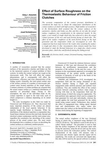
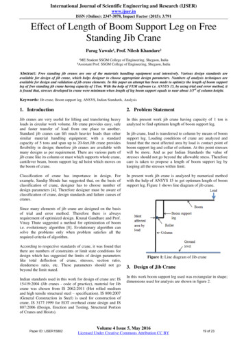
International Journal of Scientific Engineering and Research (IJSER)www.ijser.inISSN (Online): 2347-3878, Impact Factor (2015): 3.791σa Tensile Stengthγ(6)γis factor of safety whose value depends upon loadingconditions and combination of loads acting on crane. Valueof γ is chosen as 1.5 from Clause 9 [2].4.3 Total Design LoadDesign load is always greater than applied load because ofsafety factor. An assumption is made that crane underconsideration is working without wind effect, therefore totalweight applied is calculated by equation (7)(As per IS807:2006)W SL WL ψ(7)Figure 4: Boom support leg having 800 mm lengthwhere,W Total design loadSL Static load due to dead weight of boomWL Working Loadψ Dynamic Coefficient or Impact FactorThe dynamic coefficient depends upon the classification ofthe crane. Here the crane identified is from group M6 withclass of utilization “C” i.e. regular use on intensive duty withmoderate state of loading/stress [2].The Dynamic coefficientor Impact factor is selected as 1.4.Here design load taken as 22339.21 N5. Optimization of boom support leg LengthOptimization is the method of selecting best feasible solutionfrom available. In other word optimization meansmaximization or minimization of one or more functions withgiven constraints. Three techniques are available foroptimization of jib crane elements: classical approach,automated computing technique and trial and error method.In this work, trial and error method is used to get optimumlength of boom support leg, so that evaluated length of boomsupport leg gives optimum lesser value of stresses.Figure 5: Boom support leg having 1650 mm lengthThe procedure followed for trial and error method isdiscussed below:In this method, first a CAD model of complete jib crane isbuilt-in ANSYS 15, as per given dimensions of crane. Thenboundary conditions are applied. Mesh is generated forwhole crane which is shown in Figure 6, the numbers ofnodes generated for the crane which has 1518mm boomsupport leg length were 24586 and numbers of elementsgenerated were 10812. Then results obtained from ANSYS15 for deflection and various stresses are analyzed.Same procedure is followed for numbers of trials of boomsupport leg length. Two trial samples are shown in Figure 4and Figure 5.Figure 6: Meshing of crane having boom support leg lengthof 1518 mm6. Results and DiscussionThe results obtained from trial and error method arecompared and results are plotted. By using trial and errormethod with the help of ANSYS 15, it is found that 1518mm length of boom support leg is optimum length. At thisPaper ID: IJSER15802Volume 4 Issue 5, May 2016Licensed Under Creative Commons Attribution CC BY21 of 23
International Journal of Scientific Engineering and Research (IJSER)www.ijser.inISSN (Online): 2347-3878, Impact Factor (2015): 3.791length value of maximum principal stress is optimum. Figure7 and Figure 8 shows values of maximum principal stressand deflection obtained at 1518 mm of boom support leglength respectively.Figure 9:Effect of boom support leg length on deflectionFigure 7: Max. Principal Stress inJib craneFigure 9 shows that as the length of boom support legincreases the values of total crane deflection decreases. Asthe length of boom support leg increases, its weight alsoincreases.Figure 10:Effect of boom support leg length on max.principal stressThe effect of length of leg boom support leg on developedprincipal stress in crane is shown in Figure 10.At1518mm length of boom support leg, value ofmax.principal stress is minimum which is 93.877 MPa anddeflection of crane obtained is16.149mm. These values areunder limitsspecified by Indian Standards.Figure 8: Deflection of Jib craneFrom column height and boom support leg length followingrelation is generatedHeight of column 4072 2.7Length of BLS1518The value 1518 mm is near about 1/3rd of column height.Hence, it can be concluded that the length of boom supportleg from top of columnshould be 1/3rdof column height forgiven dimension ofjib crane.7. ConclusionIn this work an attempt is made to get optimum length ofboom support leg with the help of trial and error method byusig ANSYS 15. And found that 1518mm is the optimumlengthof boom support leg.Though trial and error method istime consuming, ithas given satisfactory and reliable results.Paper ID: IJSER15802Volume 4 Issue 5, May 2016Licensed Under Creative Commons Attribution CC BY22 of 23
International Journal of Scientific Engineering and Research (IJSER)www.ijser.inISSN (Online): 2347-3878, Impact Factor (2015): 3.791References[1] Indian Standard 15419:2004, Jib cranes- Code ofPractice.[2] Indian Standard 807:2006, Design, Erection and Testing(Structural Portion) of Cranes and Hoists- Code ofPractice.[3] Indian Standard 800:2007, General Construction Insteel- Code of Practice.[4] Sandip D. Shinde, “Standardization of Jib crane Designby “F.E.M. Rules” And Parametric Modeling”,International Journal of Recent Trends in Engineering,Volume 1, No. 5, May 2009.[5] Indian Standard 2062:2011, Hot rolled medium and hightensile structural steel – specification.[6] Francesco Frendo, “Analysis of the catastrophic failureof a dockside crane jib”, Engineering Failure Analysis31 (2013) 394-411.[7] A. A. Marquez, P. Venturino, J.L. Otegui, “Commonroot causes in recent failures of cranes”, EngineeringFailure Analysis 39 (2014)55-64.[8] Krunal Gandhare, Prof. Vinay Thute, “DesignOptimization of Jib crane Boom Using EvolutionaryAlgorithm”, International Journal of ScientificEngineering and Research, ISSN (Online): 2347-3878,Volume 3, Issue 4, April 2015Paper ID: IJSER15802Volume 4 Issue 5, May 2016Licensed Under Creative Commons Attribution CC BY23 of 23
available for design of jib crane, which helps designer to choose appropriate design parameters. Numbers of analysis techniques are available for design and validation of jib crane elements. In this paper an attempt has been made to optimize the length of boom support leg of free standing jib crane having capacity of 1Ton. With the help of FEM software i.e. ANSYS 15, by using trial and error method, it