Transcription
Available online at www.sciencedirect.comComput. Methods Appl. Mech. Engrg. 197 (2008) 2156–2172www.elsevier.com/locate/cmaManipulation of nanoparticles and biomolecules by electric fieldand surface tensionYaling Liu a, Kieseok Oh b, John G. Bai b, Cheng-Ling Chang b, Woonhoog Yeo b,Jae-Hyun Chung b, Kyong-Hoon Lee c, Wing Kam Liu d,*aDepartment of Mechanical and Aerospace Engineering, University of Texas at Arlington, 500 West First Street, Arlington, TX 76019, USAbDepartment of Mechanical Engineering, University of Washington, Campus Box: 352600, Seattle, WA 98195-2600, USAcNanoFacture, Inc., 3983 Research Park, Dr. Ann Arbor, MI 48108, USAdDepartment of Mechanical Engineering, Northwestern University, 2145 Sheridan Road, Evanston, IL 60208-3111, USAReceived 4 June 2007; received in revised form 24 August 2007; accepted 27 August 2007Available online 7 September 2007AbstractElectric field has become one of the most widely used tools for manipulating cells, biomolecules, and nanoscale particles in microfluidic devices. This paper presents the theory, modeling, and experimental works on manipulation of nano and biomaterials by using anelectric field and surface tension. Three-dimensional dynamic assembly of nanowires on various microelectrodes under dielectrophoreticforce is presented with discussion on capillary action and electroosmosis effects in the manipulation. The various approaches to manipulate the small scale materials are addressed both numerically and experimentally. For successful prediction and analysis on nanoscale, ahierarchical and multiscale scheme for modeling fluid transportation in nanochannels is suggested. The results show that the combinedeffects of electric field and capillary action induced forces are crucial for precise control over nanoscale materials. 2007 Elsevier B.V. All rights reserved.Keywords: Immersed finite element method; Electrokinetics; Dielectrophoretic assembly; Nanomaterials; Nanowires; Surface tension; Nanochannel1. IntroductionTransport, alignment, and assembly of nano and biomaterials in liquid phase are drawing more attention with therapid development of small scale electromechanical devices.The current trend toward high performance microsystemscan have an impact on a broad range of applications suchas medical devices, fuel cells, communication systems, andbiological or chemical sensors. To improve the performanceof such devices, controlled manipulation of the nano- andbiomaterials involved is the key issue because the materialshaving specific functions need to be assembled in a consistent manner with the design. The major challenge for themanipulation lies in the small length scale of nano and bio-*Corresponding author. Tel.: 1 847 491 7094.E-mail address: w-liu@northwestern.edu (W.K. Liu).0045-7825/ - see front matter 2007 Elsevier B.V. All rights reserved.doi:10.1016/j.cma.2007.08.012materials, which limits the effective observation either bynaked eyes or by conventional optical microscopes. Electron microscopes are powerful tools for observation thatis also limited by environmental conditions including highvacuum, material conditions, material size, etc. Furthermore, in situ monitoring of nanostructured materials duringthe manipulation and assembly is more challenging thanobservation after the assembly because of the assemblymaterials in liquid environment.Recently, rigorous computational methods have beenproposed to model, analyze, and predict nanoscale processes and behaviors in order to augment and enhanceexperiments. These modeling technologies have demonstrated the ability to investigate the behavior of bulk nanostructured materials [2,3]. These methods enable the preciseprediction of material behavior in multiple scales, which iscrucial to shorten the incubation process for manufacturing nano and biomaterials. These methods are also
Y. Liu et al. / Comput. Methods Appl. Mech. Engrg. 197 (2008) 2156–2172essential for quickly verifying a new idea on nanomaterialsrequiring an enormous effort in experiment.Various mechanisms have been proposed in recent yearsto assemble and pattern nano and biomaterials. Amongthem, electric field induced manipulation has been demonstrated by changing the amplitude of an electric potentialand its frequency [4]. The simple working principles andconvenient experimental setups involving electric forceshave been successfully applied to assemble nano and biomaterials [5]. The major effects induced by an electric fieldare dielectrophoretic force, electroosmotic flow, and electrothermal effect. The dielectrophoretic force arises frominduced dipole moments on a particle embedded in anon-uniform electric field. The electroosmosis flow is driven by the electrostatic force applied to the charged doublelayer on the surfaces of the electrodes. The electric field canalso increase the temperature of the fluid through Jouleheating. However, under most conditions discussed in thispaper, the increase of temperature due to Joule heating isfar less than 1 K, thus the electrothermal effect is negligible.Among the major forces induced by an electric field, theelectrophoretic force gained more attention due to its successful applications to gel electrophoresis for separatingnucleic acids and proteins [6,7]. The dielectrophoretic forcewas introduced in 1951 by Pohl [8] and theoretically formulated by Jones [4]. The dielectrophoretic force was used toattract and repel particles as designed due to the differencein permittivity. Besides the attraction or repulsion, themanipulation of flexible biopolymers or cells has been ofgreater interest. For example, live cells could be differentiated from dead cells by manipulating the frequency of anAC electric field [9]. Zimmermann et al. used a high-amplitude AC electric field to manipulate mammalian cells [1].Recently, more precise assembly methods have been proposed. Washizu et al. used the electroosmotic flow toimmobilize and stretch DNA molecules [10]. Chung et al.[11,12] assembled multi-walled carbon nanotubes andDNA molecules by combining an AC with DC electricfield. These technologies have allowed for the control anddeposition of individual nanoscale components in micro/nano systems.During the manipulation using an electric field, mostnanomaterials are processed in liquid phase, released fromsolution and used in liquid and gas phases. In the transitionfrom solution to gas phase, both capillary action and surface tension inevitably affect the final stage of the nanomaterials. In fact, the force induced by the capillary actionis usually a few orders of magnitude larger than thatinduced by electric field, especially in micro/nanoscaledimension. The capillary action caused by adhesive intermolecular force is dominant in the small dimension dueto the relatively small inertia. This explains why smallinsects can float on water and sometimes be trapped in asmall drop. The dexterous control of the capillary actionin material processing and manufacturing is critical regardless of its resultant effects. In spite of such a dominanteffect, the capillary action has not been paid much atten-2157tion possibly because it is not easy to be controlled in nanoscale material processing. Thus, how to utilize or minimizecapillary action is the main concern in nano- and biomaterial assembly, which may also provide an ample opportunity for the generation of new structures. Wu andWhitesides [13] and Lu et al. [14] have utilized the surfacetension due to water/air interface to assemble microscalepolystyrene ball on a patterned surface. Manoharan et al.[15], Lauga and Brenner [16] reported the experimentaland modeling results on the evaporation induced assemblyof colloidal particles. It was found that the colloidal particles absorbed at the interface of liquid droplets werearranged into a uniform pattern during evaporation. Thecreation of the unique packing was ascribed to geometricalconstraints during the drying.Combination of an electric field and capillary action cancreate more interesting results. Single walled carbon nanotube (SWCNT) bundles have been formed using both anAC electric field and capillary action by Tang et al. [17–19]. The dielectrophoretic force due to the AC field wasapplied to attract SWCNTs near a tungsten (W) tip. Inthe experiment, the dielectrophoretic force directed themotion of nanoparticles along the orientation of the field.Subsequently, the capillary action formed the fibril shapeof the SWCNTs.To move toward the next-generation assembly methods,a comprehensive understanding of the underlying physics iscrucial, but has yet to be fully realized due to the complexity of the assembly processes at such a small scale. Therehave been various numerical studies in literature onmotions of liquid or particles under an electric field. Ramoset al. [20] have reviewed the motion of particles in a suspension when subjected to an AC electric field. Wan et al. [21]have studied the dynamics of a charged particle in a fluidvia Lattice Boltzmann simulation. Dimaki and Boggild[22] have used point dipole approximation to calculatethe dielectrophoretic force and simulate the trapping process of a carbon nanotube on microelectrodes. In thesestudies, the solid particles are assumed to have no influenceon local electric field, thus behave like a point in the electricfield, which is accurate only when the particles are smallenough or far from the electrodes. To overcome these limitations, Aubry et al. [23–28] have used DistributedLagrangian Method and Maxwell Stress Tensor to studythe dielectrophoretic assembly of rigid spherical particlesin an electric field cage. It is demonstrated that the pointdipole approximation is not valid when the particle size isclose to the cage size, thus has to be replaced by the generalMaxwell Stress Tensor method. Furthermore, Liu et al.[29,30] have studied the dielectrophoretic assembly ofnanowires and the electrodeformation of cells through coupled electrokinetics and immersed finite element method[30–32] (IFEM). Electric field has also been used in liquidtransportation in micro/nano channels. Patankar et al.[33] have used finite element method to calculate thecontinuum electroosmotic flow in a 2D channel. Qiaoet al. [34–37] have studied the electroosmotic flow in
2158Y. Liu et al. / Comput. Methods Appl. Mech. Engrg. 197 (2008) 2156–2172nanochannels by molecular dynamics simulation. Similarmolecular simulation of electroosmotic transportation ina charged nanopore has been presented by Thompson [38].Currently, a complete theory or model has yet to beavailable for the three-dimensional dynamic assembly processes for multiple, arbitrary shaped nanomaterials undercomplex environments such as electric fields, surface tension, and moving boundaries. In this paper, we will discussthe fundamental physics involved in the assembly processand how ideas motivated from the immersed boundarymethod [39] can model the manipulation process. It provides an excellent demonstration of the broad range capabilities and applications of computational methods toanalyze and predict the performance of electromechanicaldevices at micrometer to nanometer scale.The outline of this paper is as follows. We first give areview of the coupled electrokinetics and IFEM formulations and the algorithm in Section 2. This coupling schemeis applied to model nanowire assembly, viruses sorting, andcell electro-deformation. In Section 3, we discuss theliquid/ion transportation in nanochannels to illustrate theconsideration of both electric and surface tension. Finally,we outline our future work on combining electric field andsurface tension for manufacturing structured nanomaterials. By comparing the analytical and computational modelsto experimental results, it is demonstrated that modelingwork can be combined with experimental work to improvethe accuracy, yield, and control of the assembly process.2. Particle assembly driven by electric fieldIn this section, we outline a method based on theimmersed boundary concept to model particle assemblyprocess driven by an electric field. During the assemblyprocess, particles are moving or even deforming in the fluidunder electrical forces. The coupled fluid-structure–electricfield interaction requires an efficient mesh-tracking procedure. The numerical scheme presented in this section combines IFEM together with electrokinetics, thus is calledimmersed electrokinetic finite element method (IEFEM).The particles of interest can be either rigid particles suchas nanowires and viruses or deformable particles such ascells. The particles are modeled by a Lagrangian mesh,while the fluid and electric field are solved in a fixed Eulerian mesh. The details of the derivation could be found in[40] and we will briefly explain the procedures here.Suppose a solid domain Xs enclosed by a boundary Cs issubmerged in a fluid domainXf, thus the entire domain X issubdivided into the solid region Xs and the fluid region Xf.In the fluid domain, the Eulerian description is used whilethe Lagrangian description is chosen for the solid domain.The material properties are assumed to be constant in thefluid and solid, and the time scale of the solid motion isassumed be much larger than the electric time scales. In thisassembly process, we assume the inherent carriers in thefluid and solid are major current carriers and the effect ofions in the fluid is ignored. We consider the case of lowconducting liquids in this section and the formulationderived within the framework of the leaky dielectric model.It should be mentioned that in Section 3, a more generalformulation is used to study liquid/ion transportation innanochannels, where we consider conducting liquids withbulk and surface charges.2.1. Coupled electrokinetics and fluid-structure interactionThe IEFEM was recently developed by Liu et al. [40] tosolve coupled fluid-structure interaction and electrokineticsproblems. Because much of the following has already beenderived in detail in Liu et al. [40], we refer the interestedreader to those works for further details.Motivated by Peskin’s immersed boundary method[39,41,42], as in Ref. [40], an extra volumetric force is introduced to avoid the complex re-meshing usually encountered in the fluid-structure interaction problems. Thisextra force FFSI, called the fluid-structure interaction force,is defined as ðqs qf Þð vs gÞ þ r ðrs rf þ rM Þ; in Xs ;FFSI ¼0; in X n Xs ;ð1Þwhere v is the velocity, q is the density and r is the Cauchystress tensor. s and f donate for solid and fluid respectively.rM is the time averaged Maxwell stress representing theelectric force. Brownian motion is not considered heredue to negligible influence on the motion of particles closeto electrodes [8,20].For a Newtonian fluid of uniform viscosity, rf can bewritten asrf ¼ pf I þ l½rvf þ ðrvf ÞT ;ð2Þfwhere l is the fluid viscosity and p is the hydrostaticpressure.For a hyper-elastic solid, we havers ¼ ps I þ J 1 Fð2ðc1 þ c2 TrðCÞI 2c2 CÞÞFT ;oxoXð3Þou.oXwhere the deformation gradient F ¼ I þThe Cauchy–Green deformation tensor is defined as C FTF,J jFj, where c1 and c2 are the material constants.The electric field is coupled to the fluid/solid motionthrough rM. For an AC field, the time averaged Maxwellstress tensor is expressed as [43]: 1 2ð4ÞrM ¼ Re eE E þ E E jEj I ;!!!! !4 where E is the electric field strength, E is the complex con!!jugate of E, Re e!!is the real part of the complex permit-tivity e expressed by material conductivity and permittivity!as e ¼ e þ ðc jxÞ.!To interpolate between the Eulerian and Lagrangiandomains, a restriction operator Lst from X onto Xs is neededto make the system complete:ðLXst wÞðX; tÞ wðxðX; tÞ; tÞ8X 2 Xs0 :ð5Þ
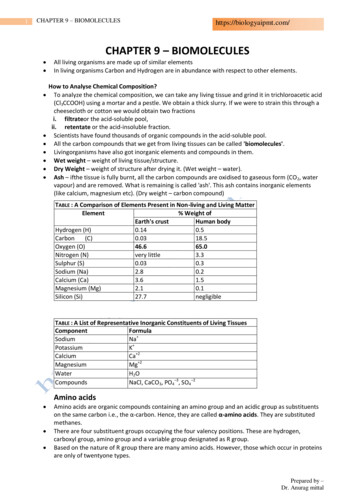
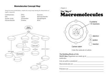
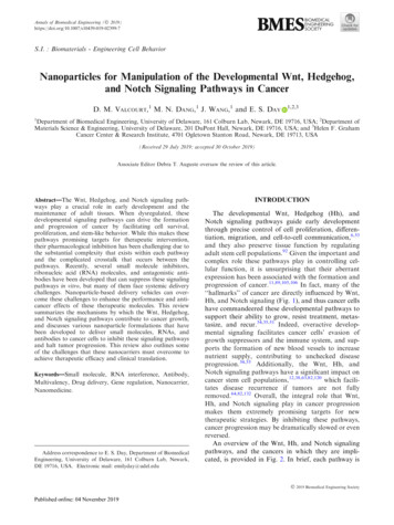
Y. Liu et al. / Comput. Methods Appl. Mech. Engrg. 197 (2008) 2156–2172With this mapping function, we obtain the solid velocityand displacement from the Eulerian space asvs ¼ Lst v; in Xs ;ð6Þous¼ vs ; in Xs :ð7ÞotIt plays a role in identifying the solid velocity field from thefluid velocity on Xs.In the similar way, immersed formulation for electricfield can be obtained by introducing a extra term:8 r e s e f r/s ; in Xs ;!!ð8ÞQ¼! :f0; in X :Here, Q represents the influence of the difference in complex permittivities for fluid and solid on the electric field./ is a complex potential phasor related to E through!!E¼ r /. s and f denote solid and fluid, respectively.!!Thus, in the whole domain, we haver ð e f r /Þ þ Q ¼ 0;!ð9Þ!where8 s / ;!/¼: /f ;!on Xs ;on Xf :ð10Þ!The weak forms of the immersed system and otherdetails can be found in Ref. [40].2.2. Nanowire assembly driven by electric field and fluid flowIn recent years, assembly of nanoparticles has becomes acrucial step in many bio/MEMS devices. The assembled2159pattern largely depends on the electric field strength, electrode geometry, and electric properties of the particles. Inthis section, the developed IEFEM method is used toexplore the dynamic process of nanowires assemblybetween microelectrodes. The assembly of nanowires byan electric field is mainly controlled by dielectrophoreticforces, and has been investigated both numerically andexperimentally in [29]. Such assembly technique has beenimproved recently by introducing fluid flow in assembly,thus taking advantages from both electric field and fluidflow. As an example, an interesting phenomenon underthe combined effect of fluid flow and electric field, pivotingof a nanowire during assembly, is presented here.In the experiment, Au electrodes which have 50 lm widegaps are patterned on 130 nm thick thermally oxidized silicon wafer by photolithography. The fluid channel is madeof polydimethylsiloxane (PDMS) (Sylgard 184, Dow Corning Corp.). It is bonded to the electrodes by using stampand-stick bonding technique [44]. The channel cross sectionis 500 lm wide and 40 lm high. SiC nanowires (AdvancedComposite Materials Corporation, Greer, SC) are used inthe experiment, which have 1–100 lm in length and 300–500 nm in diameters. The concentration of nanowiresolution is 5.0 lg/mL in dimethylformamide (DMF). Thesolution is placed in the inlet of the fluidic device and theflow is controlled by a syringe pump (Pump 11 pico plus,Harvard Apparatus). An AC field (0.5 Vpp, 5 MHz) isapplied for the assembly of nanowires. The assembly process was recorded by a video-camera (DXC-390, SonyCorp.) through an optical microscope.In the experiment, a nanowire is approaching the electrode by fluid flow (Fig. 1a) and one end of the nanowireis landed on an edge of the electrode. After landing, oneend of the nanowire is pivoted and the other end is rotatingFig. 1. Alignment of a SiC nanowire with pivoting process in DMF; (a) time 0 s, (b) time 1.5 s. The nanowire of interest is colored in black for clearview, (c) time 2 s, (d) time 3 s (AC voltage: 500 mVpp at 5 MHz).Fig. 2. Pivot simulation: the flow is directed from left to right. The nanowire is attracted, pinned at one end, rotated, and oriented to the fluid flowdirection on the electrodes. (a) time 0 s, (b) time 1 s, (c) time 2 s, (d) time 3 s.
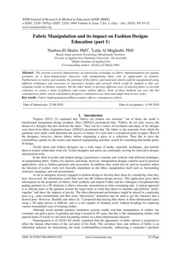
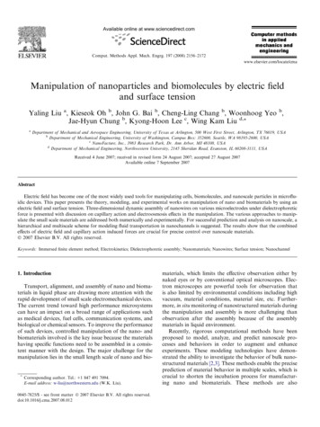
2160Y. Liu et al. / Comput. Methods Appl. Mech. Engrg. 197 (2008) 2156–2172Table 1Problem configuration for the pivot simulationTable 2Properties of the three virus types used in the simulation of virus detectionFluid29,525 nodesq 1 g/cm3157,079 elementsl 0.01 g cm/scf 0.0056 S/cmef 20e0Nanowire1536 nodesqs 1 g/cm3Dt 0.03 s6253 elementslength 6 lmdiameter 600 nmcs 0.0112 S/cmes 100e0cap radius 300 nm(Figs. 1b and c). The simulated pivot process is shown inFig. 2, which agrees well with the experimental observation. The details of the simulation are shown in Table 1.It should be noted that the method we proposed is generaland applicable to different types of particles and mediums.The values of permittivity and conductivity vary largelyfor different types of particles and mediums, leading todifferent values of complex permittivities. For example,at 5 MHz, the complex permittivities of SiC and ethanolare 2.2 · 10 10 1.6 · 10 16i F/m and 4.0 · 10 10 2.0 ·10 8i F/m, respectively. These complex permittivities contain either a large real part or a large imaginary part, representing a special case only. The values in the paper arechosen to be general, at which the complex permittivitieshave an imaginary and real part in the same order of magnitude, i.e., 0.18 0.18i nF/m and 0.9 0.36i nF/m. Atthese chosen values, both permittivity and conductivitycontribute to the DEP force calculation, which is the oneof the most computationally challenging cases, thus demonstrate the capability of our method.2.3. Virus depositionIn recent years, lots of so called lab-on-a-chip deviceshave been proposed for point-of-care diagnostics and prognostics of various diseases. One important procedureinvolved in the diagnosis is to selectively separate one typeof virus out of a suspension with multiple viruses. Since anelectric field can be easily applied and controlled, individual virus manipulation by electric field induced forces hasattracted considerable interests. The working principle ofselective deposition by electric field is that the sign ofdielectrophoretic force on the particle is determined bythe electric properties of the particle and the medium andthe electric field frequency. By applying an AC field of aspecific frequency, one type of viral particles can be selectively attracted under positive dielectrophoresis. We demonstrate the feasibility of the selection process throughmodeling the electric deposition of three different types ofviruses. Suppose a sample solution contains the Inovirus,Influenza, and Bacteriophage P22. The physical and electric properties of these three viruses [45] are listed in Table2. The entire virus is assumed to be a homogeneous rigidbody. The DEP force versus frequency curve for each individual virus is shown in Fig. 3a. The DEP force on a virusis calculated through the Maxwell stress tensor methoddescribed in Eq. (4). The proposed strategy to sort the threekinds of viruses is as follows. First, the frequency indicatedInovirusInfluenzaBacteriophage P2270330Permittivity (e0)Conductivity (mS/m) 8803Size (nm)200 (length) 100 (diameter) 65 (length)20 (diameter)by the solid arrow (5 MHz) in Fig. 3a is chosen to selectively attract Influenza in the first array of electrodes inour proposed device since only Influenza particles experience positive DEP force. Then, the frequency indicatedby the dashed arrow ( 1 MHz) is chosen to attract Inovirus in the second array of electrodes. Finally, the frequencyindicated by the hollow arrow ( 100 KHz) is chosen todeposit Bacteriophage.The simulations for selectively deposition of six viruses(two viruses from each type) on three pairs of parallel–rectangular-shaped electrodes are shown in Figs. 3b–e. The sixviruses are initially aligned at the same height of 0.2 lmabove the electrode surface. An AC field of 5 MHz isapplied to the first set of electrode pair. An inflow of18 lm/s is applied to transport the virus. The flow profileof the cross-section in the middle of the channel is shownin Fig. 3f. The electric field distribution across the electrodepairs is shown in Fig. 3g. From the electric field distribution, it shows that each electrode pair generates a local electric field that has little impact on the nearby electrode pairs.The Inovirus and Bacteriophage are under negative DEP,while the Influenza is under positive DEP at 5 MHz. Thus,only Influenza is trapped exactly in the gap and the othertwo are transported by the flow toward the second electrode pair. On the second electrode pair, when a 1 MHzAC field is applied, the DEP force on the Inovirus isswitched to be positive while Bacteriophage is still undera negative DEP. Thus, only Inovirus is attracted on the second electrode pair, while Bacteriophage is again transported by the flow. On the third electrode pair, when anAC field of 100 KHz is applied, the Bacteriophage is finallydeposited under a positive DEP. Through these three steps,three different groups of virus are selectively deposited.2.4. Electro-manipulation of cellsThe ability to manipulate deformable particles, especiallyliving cells, is essential to biological and medical applications. For example, Zimmermann et al. used a high-intensityAC field to manipulate mammalian cells [31]. By applying anAC field of 2-MHz frequency and 2-kV/cm strength, theyobserved the electrodeformation of human erythrocytes intoa stretched form. The cells were aligned vertically betweenelectrodes by an AC field between two cylindrical electrodes.Various equilibrium cell shape and assembly patterns underthe uniform and non-uniform electric fields were observed.However, there has been no efficient and accurate numericaltool to characterize such electro-mechanical manipulation
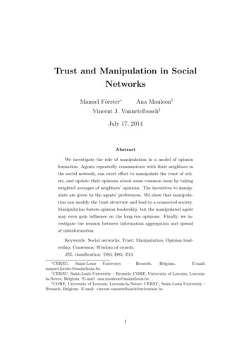
Y. Liu et al. / Comput. Methods Appl. Mech. Engrg. 197 (2008) 2156–2172a1 MHz21615 MHz100 KHzbInfluenzaInoviruscBacteriophageFirst electrode pairThird electrode pairSecond electrode pairdefgFig. 3. Simulation on selective deposition of six viruses: an 18 lm/s flow is directed from left to right. The first electrode pair is operating at 5 MHz, thesecond pair is at 1 MHz, and the third pair is at 100 KHz. Influenza, Inovirus, and Bacteriophage are selectively deposited on the first, second, and thirdelectrode pairs consequently. (a) Polarization factor of viruses at different frequencies. The polarization factor here is defined as Re(Kf) from the expressionhFDEP i ¼ Ce f ReðK f Þrj Ej2 , where C is 3/2 the volume of the virus and e f is the medium permittivity. The polarization factor given by the effective dipole!theory for a spherical particle is ReðK f Þ ¼ Refð!es !e f Þ ð!e s þ 2!e f Þg. (b) time 0 ms, (c) time 15 ms, (d) time 30 ms, (e) time 45 ms, (f) velocityprofile in the channel, (g) electric field across three electrode pairs.process. Here, we use our numerical tool to simulate the electro-deformation of cells and explore the underlying physicsinvolved in this process.In the simulation, a biconcave shaped erythrocyte isplaced between two parallel electrodes, but closer to oneside of the electrode compared to the other side. The conTable 3Problem configuration for cell electro-manipulation simulationFluidSolid32,156 nodesfiguration of this simulation [1] is listed in Table 3. Once a2-kV/cm AC field is applied, the cell is found to bedeformed into a prolate shape due to Maxwell stress generated by the electric field. In particular, the cell is attractedto one side of the electrode and stretched to the other side,forming an asymmetric bottle shape. A comparison of thesimulated shape with the experimental image by Zimmermann et al. is given in Fig. 4.cf 0.00085 S/cmq 1 g/cm331,234 elements(150 · 15 · 15)l 0.01 g cm/sef 80e0809 nodesq 1 g/cm33684 elementsD 20 lmcs 0.005 S/cmes 70e03. Ion and liquid transportation in nanochannelsIn recent years, nanoscale fluidic channels are believedto provide a platform for single molecule detection and
2162Y. Liu et al. / Comput. Methods Appl. Mech. Engrg. 197 (2008) 2156–2172Fig. 4. Electro-deformation of cells under a strong electric field. (a) Simulated deformed shape of the cell; (b) the experimental image from [1](Zimmermann et al., Electromanipulation of mammalian cells: fundamentals and application, 2000, Copyright IEEE, Reproduced with permission).evaluation. The transportation of ion species, biomolecules, and chemical agents in nanofluidic channels providesa novel tool for controlling and separating such molecules.The difference of nanochannels from micro/macro scalechannels originates from the small dimension. At such asmall scale, surface-charging effect dominates the fluidbehavior. Two major factors are involved in the diffusionof liquid in a nanochannel: ion diffusion and capillaryaction. The diffusion of the liquid into the nanochannelcan be triggered by the diffusion of ions into the channelcovered by surface charges. Capillary action at air–liquidinterface may also result in liquid filling. Such filling process strongly depends on liquid property, ion concentration, and the liquid–wall interface. The physics involvedin the ion diffusion process and capillary action areaddressed in this section.3.1. Capillary action driven flowLiquid filling is a phenomenon that fluid is introducedthrough a channel by surface tension or surface charges.Surface effect is dominant as the size of a channel decreasesto micro or nanoscale. Two major forces in such smallchannel are surface tension and an externally applied pressure or vacuum. Without external forces, fluid flow is generated by capillary action when the contact angle is lessthan 90 (hydrophilic). When the contact angle is greaterthan 90 (hydrophobic), the fluid has to be pressurized toinduce a fluid flow. To trigger fluid flow in a hydrophobicchannel, the external pressure has to be larger than thepressure jump across the interface. The detailed analysisof capillary action-driven flow has been presented by Yanget al. [46].The liquid–air interface is an evolving surface driven bythe surface energy. The dynamics of the liquid/air interfacein the nano channel is controlled by the capillary force andviscous friction from the channel wall.The pressure drop across the air–liquid interface isdescribed by the Young–Laplace equation:Pc ¼2c cosðhÞ;rð11Þwhere r is the channel radius, c is the surface tension of theliquid, and h is the contact angle.The rate of liquid penetration into a small channel ofradius r is given by the Washburn equation:dl ðP þ P c Þr2¼;dt8llð12Þwhere P is the external driving pressure, l is the viscosity,and l is the penetration length.Solving Eq. (12) without external driving pressure givesan estimation of the kinetics of the capillary filling �ffiffiffiffipffic cosðhÞr pffil¼a t¼ t:ð13Þ2lEq. (13) is based on a constant capillary pressure (Eq. (11))driving the filling process and a linear hydraulic flow resistance. This resistance increases in proportion to the lengthof the liquid plug. In micro/nano scale channel, the gravityforce is much smaller than the surface tensi
Manipulation of nanoparticles and biomolecules by electric field and surface tension Yaling Liu a, Kieseok Oh b, John G. Bai b, Cheng-Ling Chang b, Woonhoog Yeo b, Jae-Hyun Chung b, Kyong-Hoon Lee c, Wing Kam Liu d,* a Department of Mechanical and Aerospace Engineering, University of Texas at Arlington, 500 W