Transcription
Test Preparation Study GuideforCoal Miner CertificationUNDERGROUND ELECTRICIAN
Test Preparation Study GuideForCoal Mine Electrical CertificationUNDERGROUND ELECTRICIANThis guide was developed for the Utah Labor Commission by Bruno Engineering, Price, Utah.
TABLE OF CONTENTSUNDERGROUND ELECTRICIANSectionPrefacePage13FormulasTest #1Test #1-Test #1-Test #2Test #2-Test #2-Test #3Test #3-Test #3-Test #4Test #4-Test #4-Test #5Test #5-Test #5-Test #6Test #6-Test #6-Test #7Test #7-DC Theory and ApplicationDC Theory and ApplicationSample QuestionsDC Theory and ApplicationAnswer SheetAC Theory and ApplicationAC Theory and ApplicationSample QuestionsAC Theory and ApplicationAnswer SheetElectric Circuits and EquipmentElectric Circuits and EquipmentSample QuestionsElectric Circuits and EquipmentAnswer SheetPermissibility of Electrical EquipmentPermissibility of Electrical EquipmentSample QuestionsPermissibility of Electrical EquipmentAnswer SheetMine Law - 30 CFR, Part 75 (Underground)Mine Law - 30 CFR, Part 75 (Underground)Sample QuestionsMine Law - 30 CFR, Part 75 (Underground)Answer SheetNational Electrical CodeNational Electrical CodeSample QuestionsNational Electrical CodeAnswer SheetPractical ExaminationPractical ExaminationSample 48Insert from Surface Electrician Study GuideTest #5Test #5Test #5-Mine Law - 30 CFR, Part 77 (Surface)Mine Law - 30 CFR, Part 77 (Surface) Sample QuestionsMine Law - 30 CFR, Part 77 (Surface) Answer Sheet151154164
PrefaceThe Code of Federal Regulations, under authority of the Federal Coal Mine Health and SafetyAct of 1969 (Public Law 91-173) states that “all electrical equipment shall be frequentlyexamined, tested, and properly maintained by a qualified person to insure safe operatingconditions.” An individual may become qualified as an underground coal mine electrician asindicated below:75.153 Electrical work; qualified person.(a) Except as provided in paragraph (f) of this section, an individual is a qualifiedperson within the meaning of §§ 75.511 and 75.512 to perform electrical work (otherthan work on energized surface high-voltage lines) if:(1) He has been qualified as a coal mine electrician by a state that has a coalelectrical qualification program approved by the Secretary: or,(2) He has at least 1 year experience in performing electrical work underground ina coal mine, in the surface work areas of an underground coal mine, in asurface coal mine, in a non-coal mine, in the mine equipment manufacturingindustry, or in any other industry using or manufacturing similar equipment,and has satisfactorily completed a coal mine electrical training programapproved by the Secretary; or,(3) He has at least 1 year experience prior to the date of application required byparagraph (c ) of this section, in performing electrical work underground in acoal mine, in the surface work areas of an underground coal mine, in a surfacecoal mine, in a non-coal mine, in the mine equipment manufacturing industry,or in any other industry using or manufacturing similar equipment, and heattains a satisfactory grade on each of the series of five written tests approvedby the Secretary and prescribed in paragraph (b) of this section.(b) The series of five written tests approved by the Secretary shall include thefollowing categories:(1) Direct current theory and application;(2) Alternating current theory and application;(3) Electric equipment and circuits;(4) Permissibility of electric equipment; and,(5) Requirements of Subparts F through K of this Part 75.(c) In order to take the series of five written tests approved by the Secretary, anindividual shall apply to the District Manager and shall certify that he meets therequirements of paragraph (a)(3) of this section. The test will be administered in theCoal Mine Safety and Health Districts at regular intervals or as demand requires.(d) A score of at least 80 percent of each of the five written tests will be deemed to be asatisfactory grade. 1 percentage point shall be added to an individual’s score in eachtest for each additional year of experience beyond the 1 year minimum requirementspecified in paragraph (a)(3) of this section; however, in no case shall an individualbe given more than 5 percentage points for such practical experience.(e) An individual may, within 30 days from the date on which he received notificationfrom the Administration of his test scores, repeat those on which he received an1
unsatisfactory score. If further retesting is necessary after the initial repetition, aminimum of 30 days from the date of receipt of notification of the initial retestscores shall elapse prior to such further retesting.(f) An individual who has, prior to November 1, 1972, been qualified to performelectrical work specified in §§75.511 and 75.512 (other than work on energizedhigh-voltage lines) shall continue to be qualified until June 30,1973. To remainqualified after June 30, 1973, such individual shall meet the requirements of eitherparagraph (a) (1), (2), or (3) of this section.(g) An individual qualified in accordance with this section shall, in order retainqualification, certify annually to the District Manager that he has satisfactorilycompleted a coal mine electrical retraining program approved by the Secretary.75.154 Repair of energized high voltage lines; qualified person.An individual is a qualified person within the meaning of §75.705 for the purpose ofrepairing energized surface high voltage lines only if he has had at least 2 yearsexperience in electrical maintenance, and at least 2 years experience in the repair ofenergized high voltage surface lines located on poles or structures.This study guide has been prepared for the Utah Labor Commission specifically to provideguidance for those individuals who desire to prepare themselves for Federal qualifications asmine electricians by taking the Utah State Coal Mine Electrician Examination by BrunoEngineering, Price Utah. The Utah State Coal Mine Electrician qualification program has beenapproved by MSHA. This study guide is not intended to serve as the sole source ofpreparation, but rather as a tool toward that end.The study guide is divided into sections for each testing category for underground coal mineelectrician qualification. The specific sections are listed below. A set of typical examinationquestions are provided for each section. Also, in each test category an outline is providedwhich gives topics that are to be tested on in the category.Test #1 - DC Theory and ApplicationTest #2- AC Theory and ApplicationTest #3 - Electric Circuits and EquipmentTest #4- Permissibility if Electric EquipmentTest #5- Mine Law 30 CFR Part 75 (Underground)Test #6- National Electric CodePractical- Prints and Meters2
Electrical Problem Solving Formulas - VAEE -NIILISCpfXXLXCZfVoltageCurrent in amperes (amps)Resistance in ohmsPower in wattsTotal Resistance in ohmsFull load currentHorsepowerTransformer primary turnsTransformer secondary turnsTransformer primary voltageTransformer secondary voltageTransformer primary currentTransformer secondary currentKilovolt AmperesVolt AmperesPhase to phase voltagePhase to neutral voltagePhase currentLine currentShort circuit currentPower factorTotal reactance in ohmsInductive reactanceCapacitive reactanceImpedanceFrequency in Hertz3
FORMULASDC Theory:SERIES ONLY:Ohm’s LawRt R1 R2 R3 etc.(Ohms)Et E1 E2 E3 etc.(Volts)I is constant: (Amps)PARALELL ONLY:Rt 1(Ohms)etc.1 1 1R1 R2 R3Power FormulaRt Rif all resistors are equalNIt I1 I2 I3 etc.E is constant: (Volts)Ohm’s Law and Power Formula CombinedFormulas:E IxRE E P/II P/EI E/RI /DC Series:Rtotal R1 R2 R3 P E²/RP I² x RR E/IR P IxE//DC Paralell:Rtotal (R1 x R2) / (R1 R2)Etotal ER1 ER2 ER3 Itotal IR1 IR2 IR3 Itotal IR1 IR2 IR3 Etotal ER1 ER2 ER3 AC:E IxZEEffective 0.707 x EPeakI E/ZZ E/IEAverage 0.637 x EPeakEPeak 1.414 x EEffective1XL 2 ח fLXc 1 / (2 ח fC)Z R² (XL – Xc)²(Amps)
Electrical FormulasTransformers:Np/Ns Ep/Es Is/IpEФ. Ф EФ.N x 1.732EФ.N EФ. Ф/ 1.732Three Phase Transformers:DELTA:IL I Ф * 1.732I Ф IL 11.732EL E ФEФ IL I ФWYE:EL E Ф 1.732EL 11.732ToFindSingle PhaseThree PhaseDCAmps(KVA x 1000) / E(KVA x 1000) / (E x 1.732)Not applicableAmps(HP x 746) / (E x Eff x PF)(HP x 746) / (E x 1.732 x Eff x PF)(HP x 746) / EAmps(KW x 1000 / (E x PF)(KW x 1000) / (E x 1.732 x PF)(KW x 1000) / EKW(I x E x PF) / 1000(I x E x 1.732 x PF) / 1000(I x E) / 1000KVA(I x E) / 1000(I x E x 1.732) / 1000Not applicableHP(I x E x Eff X PF) / 746(I x E x Eff X PF x 1.732) / 746(I x E x Eff) / 746WIxEI x E x 1.732IxETransformer Short Circuit Current Rated Full-Load CurrentPercent ImpedancePower in Three – Phase Systems:P ILEL ( 3) (PF)P IФ EФP ILEL ( 3)Also:PA 3 (P Ф)kVA is PA(in kiloVoltAmperes)51 hp 746 watts
TEST #1DC THEORY AND APPLICATION6
UTAH MINE ELECTRICIAN CERTIFICATIONEXAMINATION STUDY GUIDETest #1 – DC Theory and Application OutlineA. Definitions1. Semiconductors2. Electric Current3. Direct Current4. Conventional Current Flow5. Electronic Current Flow6. Voltage7. Electromagnetism8. Rectifier9. DiodeB. Ohm’s Laws1. Applied to Series DC Circuitsa. Total circuit currentb. Total circuit resistancec. Voltage drop across each series resistor2. Applied to Parallel DC Circuitsa. Total circuit currentb. Equivalent or total circuit resistancec. Voltage drop across each parallel resistorC. Power Formula1. Total power consumed by the circuita. Series circuitsb. Parallel circuits2. Power dissipated by individual resistorsa. Series circuitsb. Parallel circuitsD. Battery Connections and Resulting Voltage1. Series2. Parallel3. Series-ParallelE. DC Motors1. Operating characteristics of various types of DC motorsa. Seriesb. Shuntc. Compound2. Connections of various types of DC motorsa. Seriesb. Shuntc. Compound3. Typical symptoms of low voltage applied to DC motors4. Methods of changing the rotation of DC motors7
F. DC Equipment Grounding Methods (Shuttle Cars)1. Diode2. Third wire (separate frame ground conductor)G. DC Motor HP to KW Conversion1. 0.746 KW 1 HP2. 746 W 1 HP8
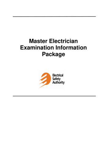
THE ELECTRON THEORYAtomic StructureThe modern explanation of electricity is by means of the electron theory, which is based upon theatomic structure if matter. Practically everything around us occupies space and has weight. We callthese things matter. All matter is composed of tiny particles called molecules. Matter can befurther broken down into fundamental constituents called elements, the tiniest particles of which arecalled atoms. An atom is the smallest particle of an element that shows its chemical and physicalproperties. A molecule is the smallest combination of atoms that form a compound of variouselements. For a better understanding of the relationship between atoms, molecules, and elements, Iwill use the example of the water molecule shown in Figure 1.1.Figure 1.1 – Illustration of a water (H2O) Molecule.Note that the water molecule is composed of two hydrogen atoms and one oxygen atom. Hence thechemical formula for water is H2O. Hydrogen and oxygen are also elements.There are 98 known elements, of which 92 occur in nature and six are artificially produced in atomsmashers and nuclear reactors. Since there are 98 elements, there must be 98 different types ofatoms.The most widely accepted theory on atomic structure is Bohr’s theory. According to Bohr’s theory,atoms actually have a complex structure, resembling somewhat a miniature solar system. An atomconsists of a central nucleus of positive charge around which tiny, negatively charged particles,called electrons, revolve in fixed orbits, just as the planets revolve around the sun. In each type ofatom, the negative charge of all the orbital electrons just balances the positive charge of the nucleus,thus making the combination electrically neutral.The positively charged nucleus is made up of two fundamental particles known as the proton andneutron. The proton is a relatively heavy particle (1840 times heavier than the electron) with apositive ( ) charge, while the neutron has about the same mass as the proton, but has no charge atall.9
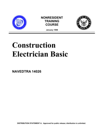
The positive charge on each proton is equal to the negative charge residing on each electron. Sinceatoms are electrically neutral, the number of protons in the nucleus is equal to the number ofelectrons revolving around the nucleus. A diagram of the Bohr model of the hydrogen atom isshown in Figure 1.2.Figure 1.2 – Bohr model of a hydrogen atom.Section 1.01 TABLE 1Section 1.02 ParticleElectronProtonNeutron-1 10ChargeWeight1/184011All atoms are made up of protons, neutrons, and electrons. The difference between variouselements results from the number and arrangement of the protons, neutrons, and electrons withintheir atoms. The elements are arranged according to their atomic number, which is equal to thenumber of electrons revolving around the nucleus. Thus an atom of hydrogen has a single electronspinning around its nucleus, while an atom of uranium has 92 electrons spinning about the nucleus.The orbits of these electrons are arranged in “shells” about the nucleus, each shell having a definitemaximum capacity of electrons. The capacity of successive shells from the nucleus out is 2,8,18,and 32 electrons; however, the outermost shell contains never more then eight electrons. It is thisoutermost shell which determines the chemical valence of an atom and its principle physicalcharacteristics. The outermost shell is also the most important for electricity, since it is the only onefrom which electrons are relatively easily dislodged to become “free” electrons capable of carryinga current in a conductor. The electrons in the inner shells cannot be forced out easily from theirorbits and, hence, are said to be “bound” to the atom.Free ElectronsElectrons that have become dislodged from the outer shell of an atom are known as free electrons.These electrons can exist by themselves outside the atom, and it is these free electrons which areresponsible for most electrical and electronic phenomena. Free electrons carry the current inordinary conductors, as well as in all types of electron tubes and semiconductors.Insulators and Conductors“Conductors” are materials that have free electrons; those having tightly bound electrons areclassed as “insulators”. It seems that the atoms of most metals are loosely hung together, or theyhave many free electrons. That is, the attraction between the electrons and the nucleus is weak, and10
it is easy to push out electrons. In other words, most metals have low resistances and are calledgood conductors. Most non-metals are just the opposite of this; they have tight atoms which havefew free electrons, they are extremely poor conductors and are called insulators.We cannot classify all substances as either conductors or insulators. There is no sharp dividing line.Electricians simply use the best conductors for wires or cables to carry current, and the poorestconductors for insulators to prevent the passage of current. Below is a table listing some of thebetter conductors and insulators (poorest luminumBrassZincCarbonInsulatorsDry airGlassMicaPlasticRubberAsbestosParaffinDry woodOil (only certain types)Electric CurrentThe free electrons in a conductor are ordinarily in a state of chaotic motion in all possibledirections. But when an electromotive force (emf) or voltage, such as that provided by a battery isconnected across a conductor, the free electrons are guided in an orderly fashion, atom to atom fromthe negative terminal of the battery, through the wire, to the positive terminal of the battery. Thisorderly drifting motion of free electrons under the application of an electromotive force constitutesan electric current. Although the electrons drift through the wire at a relatively low speed, theimpulse is transmitted almost at the speed of light. Note that the electron current continues to flowonly as long as the wire remains connected the battery. The wire itself remains electrically neutral,since electrons are neither gained nor lost by the atoms within the wire. Thus, the free electronspresent within the wire act simply as current carriers, which are continually being replaced, butnone are lost. Refer to Figure 1.3 for an illustration of current flow through a conductor.Figure 1.3 - Conduction of electricity through a conductor.11
Until recently it was believed that current flows from positive to negative, which is conventionalcurrent flow as it is shown is Figure 1.3. It has since been proven that current flows from negativeto positive, which is also shown in Figure 1.3. Although conventional current has been widely usedin the markings of meters, formulation of electrical rules, and in many textbooks, we shall not use itas our standard. From now on the term “current” designates electron flow from negative (-) topositive ( ).ELECTRICAL SOURCESThe chief sources of electricity are mechanical, chemical, photoelectric, thermoelectric, andpiezoelectric in nature. Electricity may be produced mechanically in two ways. When certainmaterials are rubbed together, electrons are transferred by friction from one to the other, and bothmaterials become electrically charged. These charges are not in motion, but reside statically oneach substance and hence this type of electricity is known as static electricity or electrostatics.Electricity may also be generated mechanically by the relative motion of a conductor with respect toa magnetic field, a process known as induction. The interaction of electric and magnetic fields isstudied in a branch of electricity called electromagnetism. Practically all commercial electricity isproduced by electromagnetic generators.Electricity can be generated chemically by inserting two dissimilar metals, such as zinc and copper,into a conducting solution called electrolyte. An electromotive force (emf), or voltage is produced,which can cause current to flow through an externally connected conducting circuit. Electricityproduced by chemical action is called electrochemistry.Sunlight or artificial illumination falling upon certain photosensitive materials produces electricityby knocking out free electrons from the surface of the material. This process is known asphotoelectric emission, or simply photoelectricity.When the junction of two dissimilar metals, such as iron wire welded to copper wire, is heated, anelectromotive force (emf) appears between the free ends of the metals. Such a junction is called athermocouple and the process is termed thermoelectricity.Electricity, finally, may be generated by the mechanical compression, stretching and twisting ofcertain crystals, such as quartz. Materials that permit generating an emf by mechanical pressure arecalled piezoelectric and the process is known as piezoelectricity.12
MAGNETISMTheory of MagnetismModern theory attributes magnetism to the motion of electrons within the atom, for it is known thatmoving electron constitutes an electric current and that an electric current produces a magneticeffect. One may think of a magnetic material as being made up of many very small magnets. Whenan un-magnetized magnetic material is place in a magnetic field, these small magnets alignedthemselves in a definite direction as the intensity of the field is increased, and magnetic poles ofincreasing strength are produced in the substance. The multitude of tiny magnets are lined up sothat all the north poles face one direction and all of the south poles in the opposite direction. Thusthe billions of millions of individual molecular magnets, because they all face the same direction,aid one another in creating a strong magnetic field.Iron and steel can be made to attract other pieces of iron and steel. This attraction is known asmagnetism. The bar magnet shown below has a north and a south end just as the earth has a Northand a South pole, in fact the earth can be considered as just a big magnet.If two bar magnets are placed with a North end and a South end as shown below, they will attracteach other.If they are placed with either the North ends or South ends together they will repel each other.These are permanent magnets and are made out of hard steel. Iron and steel can be magnetized.Other metals that can be magnetized slightly are nickel and cobalt. Temporary magnets are made ofsoft iron. Most other materials are non-magnetic and cannot be magnetized. Copper cannot bemagnetized. Electromagnets are made by winding coils of wire around soft iron. When an electriccurrent flows through the wire the soft iron will become strongly magnetized. When the currentstops flowing the iron will lose its magnetism.13
Magnetic FieldsMagnets exert a pull on each other even though they are not touching. The space around themagnets in which this magnetic push or pull exists is known as a magnetic field.Lines of ForceThis magnetic field may be represented by lines of force. We assume that these lines of force flowfrom the North end of magnet to the South end of a magnet. These lines of force are just an easyway to show on paper how a magnetic field is formed and where the magnetic field is weaker andwhere it is stronger. These lines of force are usually called flux of magnetic flux.Field StrengthThe number of flux lines and how close together they are shows the field strength or flux density ofa magnetic field. Notice that the flux density is much higher in the iron than in the air around themagnet. This shows though the flux density can be increased if an iron path is used instead of air.Although the lines of force will go through air, cardboard or any other material, the magnetic fieldwill be much weaker than when it is in iron.Magnetic Fields Around Electrical ConductorsEvery conductor that has as electrical current flowing through it will produce a circular magneticfield around the conductor.How far out the field will extend and how great the flux densities will depend on how much currentor how many amps are flowing in the wire. The greater the amps the greater or more intense themagnetic field will be.A straight current carrying conductor has no poles. If the wire is formed in a coil it produces amagnetic field that looks similar to a magnet.If a piece of soft iron is put in the center of the coil, or solenoid as it is usually called, the magneticlines of force can travel through the iron much easier and a more intense magnetic field is formed.This is an electromagnet. The strength of the electromagnet is determined by its ampere-turns, thatis the number of turns of wire times the amount if current going through the wire.The most important application of magnetic fields is in the operation of motors and generators. Ifwe move a conductor across a magnetic field rapidly and at right angles to the lines of flux, we willgenerate a voltage in the conductor. The more lines of flux that are cut per second by the conductorthe greater will be the “induced voltage” in the conductor. This is the basic principle in thegeneration of electricity.14
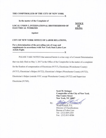
DIRECT-CURRENT CIRCUIT THEORYA direct-current (d-c) circuit is the starting place for the analysis of electrical circuits since it is themost basic and most simple circuit encountered. Let us begin this discussion by considering thesimple d-c circuit shown in figure 4.1.Figure 4.1. – A simple d-c circuitThe circuit consists of a source of electromotive force (voltage) –a battery in this case- that isdesignated by E, and a resistance (R) or load connected to the thermals of the voltage source. Theresistance (R) may represent an actual resistor or some electrical device (called a load), such as alamp, a toaster, or an electric iron, from which useful work is obtained. We also have connected aswitch (S) into the circuit, to permit opening or closing the circuit.As long as the switch is in the up or open position (shown dotted), there is no complete path forcurrent to flow and we have what is known as an open circuit. As soon as the switch is placed inthe down or closed position (shown solid), a complete, unbroken pathway (closed circuit) is formedthrough which an electric current (I) may flow. Electron current then flows from the negative (-)terminal of the battery, through the resistor and switch, and back to the positive ( ) terminal of thebattery. The switch, resistor, and connecting wires are known as the external circuit. Current alsoflows in an internal circuit, from the positive to the negative terminal inside the battery, thuscompleting the electrical path. The current flow will continue as long as the switch remains closedand as long as the voltage always flows in the same direction. The circuit is known as a directcurrent (d-c) circuit. Direct current flows in only one direction and has constant magnitude.George Simon Ohm discovered in 1827 that current (I) flowing in such a d-c circuit is directlyproportional to the applied voltage (E) and inversely proportional to the resistance of the circuit.Putting this statement, known as Ohm’s Law, into mathematical form, we obtain:Current EMF (voltage)ResistanceOr using symbols:I (amperes) E (volts)R (ohms)E IR ; R EIWhenever an electric current flows through a resistance, electric power is expended in the form ofheat. Electric current in the d-c circuit case is numerically equal to the voltage (volts) times the15
current (amperes). This relationship is expressed below using symbols. The symbol for power is Pand the unit of measurement is the watt (w).Power Current x VoltageP (watts) I (amps) x E (volts)This equation can also be expressed in the following forms:P I2RP E2RFactors Affecting ResistanceThe amount of current an electrical conductor can carry is dependent on its resistance. Theresistance of a wire depends upon the following:1. Length; as the length increases, the resistance will increase proportionally.2. Cross section; as the diameter increases, this means an increase in the area of cross section,the resistance will decrease.3. Temperature; as the temperature increases, the resistance also increases.4. The type of material also affects resistance.DEFINITIONSCURRENTThe movement of electrons through a conductor is called current. The number of electrons whichpasses a given point in one second determines the magnitude of the current. The unit ofmeasurement of the current is the ampere and it is measured with an ammeter. The symbol forcurrent is I.RESISTANCEOpposition to the flow of current through a conductor is called resistance. The unit of measurementof resistance is the ohm and it is measured with an ohmmeter. The symbol for resistance is theGreek letter, Omega ( Ω ).ELECTROMOTIVE FORCE (POTENTIAL DIFFERENCE)The external force which causes (or tends to cause) the current to flow through a conductor is calledelectromotive force (emf). The unit of measurement of electromotive force is the volt and it ismeasured with a voltmeter. The symbol for electromotive force is E.16
OHM’S LAWThe rate of current flow (in amperes) is equal to the electromotive force (in volts) divided by theresistance in ohms.I ERR EIE IxRFORCEForce is that which tends to produce motion, a change in motion, or a change in the shape of matter.WORKWhen a force overcomes a resistance and causes motion, work is done. Regardless of the forceexerted, if no motion results there is no work done.POWERPower is the rate at which work is done. Electric power is numerically equal to the voltage in voltstimes the current in amperes.P ExIE PI PIEThe unit of measurement of power is the watt. The symbol for power is P and the symbol for wattis W. One mechanical horse power is equal to 746 watts.SERIES CIRCUITA series circuit is one in which the resistances or other electrical devices are connected end to endso the same current flows in each part of the circuit.SERIES CIRCUIT LAWS1. In a series circuit, the total resistance is the sum of the individual resistances.2. In a series circuit, the same current flows in each part of the circuit.3. In a series circuit, the sum of the voltage drops across each individual circuit element isequal to the applied voltage.PARALLEL CIRCUITA parallel circuit is one in which the current may flow in more than one path.PARALLEL CIRCUIT LAWS1. In a parallel circuit the total or equivalent resistance is equal to the applied voltagedivided by the total current.2. In a parallel circuit, the voltage is the same across each branch of the circuit.17
3. In a parallel circuit, the sum of the currents flowing up to a point equals the sum of thecurrents flowing away.SHORT CIRCUITA short circuit occurs when two conductors of different potential contact each other.SERIES - PARALLEL CIRCUITConsist of groups of parallel circuit elements in series with other circuit elements.GROUNDThe term ground, which actually means the earth, is used to describe a reference for voltagemeasurements and a point of common return from one side of circuit components to that same sideof the power source.OHM’S LAW1. Definition:Ohm’s law states the current in a circuit is equal to the electromotive force in that circuitdivided by the resistance of the circuit when the temperature is kept constant.2. Formula:I EorE IxRRI Current in ampsE Voltage drop in voltsR Resistance in ohmsorR EI3. Basic RelationshipsThe current increases as the voltage drop increases, the resistance being held constant.The current decreases as the resistance increases, the voltage drop being held constant.SERIES CIRCUITSIn series circuits the current (I) has the same value anywhere in the circuit.I I1 I2 I3In series circuits the equivalent resistance of a group of resistors is equal to the sum oftheir individual resistances.RT R1 R2 R3
Insert from Surface Electrician Study Guide Test #5 - Mine Law - 30 CFR, Part 77 (Surface) 151 Test #5 - Mine Law - 30 CFR, Part 77 (Surface) Sample Questions 154 Test #5 - Mine Law - 30 CFR, Part 77 (Surface) Answer Sheet 164 . 1 Preface The Code of Federal Regulations, under