Transcription
I NGENI E URBÜRO FÜRT EC HNOLOGI E T RA NS FE RDIPL. -I NG. B. P. SCHULZ-HEISETraining ManualSTEP 5 with S5 for Windows Basic TrainingTTI Trans Tech International 2013STEP 5 S5 for Windows Training
The training documentation is for the personal use of the training participants only.The duplication of the training documentation for not licensed purposes, thepassing on, utilization and communication of the contents to third parties is notpermitted.Offense obliges to damage substitute.All rights remain at TTI, Peter Schulz-Heise.The software made available during the training class may be taken neither, nor becopied all or part or be made in other, not licensed manner, usable.TTI Ingenieurbüro fürTechnologie TransferDipl. Ing. B. Peter Schulz-HeiseStadtring 20764720 Michelstadt, GermanyTel.: 06061 3382Home page:TTIntl.comFax: 06061 71162E-Mail:PSH@TTIntl.comSimatic, STEP 5, STEP 7, S7-200 , S7-300 , S7-400 and GRAPH 5 are registered trademarks of Siemens AG,München and Berlin. Picture Source: " Siemens AG 2002, All rights reserved"Windows , Windows NT are trademarks of the Microsoft Corporation in the USA and/or other countries.InTouch and Wonderware are registered trademarks of the Wonderware Corporation.Product names are trademarks of their owners.STEP 5 S5 for Windows TrainingTTI Trans Tech International 2013
Table of ContentsPage 1Table of ContentsTable of Contents . 11Basic S5 Programming . 1-11.1Methods of Representation . 1-1Ladder Diagram .1-1Ladder diagram representation on the monitor .1-7Symbolic Programming.1-8Statement List (STL) .1-9Structure of a statement .1-9Function Block Call (STL presentation) . 1-10Control System Flowchart . 1-13Calling a Function Block . 1-161.2Structure of the Application Program . 1-17Blocks . 1-17Organization blocks (OBs) . 1-18Program blocks (PBs) . 1-18Function blocks (FBs, FXs) . 1-18Sequence blocks (SBs) . 1-18Data blocks (DBs, DXs) . 1-191.3Segment . 1-191.4PLC Program Structures . 1-201.5Linear Programs . 1-201.6Partitioned Program . 1-211.7Structured programs . 1-221.8Example of a program structure . 1-241.9Cyclic Program Processing . 1-26The Cyclic PLC Program Execution . 1-281.10CPU Start-up . 1-29RESTART OB’s . 1-29Cold Restart Routine . 1-29Restart Characteristics and Cyclic Operation . 1-311.11Cyclic Program Processing . 1-32The Cyclic PLC Program Execution . 1-341.12Organization Blocks for Interrupt-Driven Program Execution 1-35Non-Cyclic Program Execution . 1-35Cyclic Interrupt Organization Blocks (OB10 to OB18). 1-37Interrupt Driven Program Scanning . 1-38Overview of the System Interrupt OBs default settings . 1-38TTI Trans Tech International 2013STEP 5 S5 for Windows Training
Page 2Table of ContentsError Handling Organization Blocks . 1-382Statement List Instructions Structure . 2-12.1STEP 5 Operands . 2-42.2Operands, Addressing Overview . 2-7Operands Addressing . 2-7Bit Variables (Bit Operands) . 2-9Byte Variable (Byte Operands) . 2-11Word Variable (Word Operands) . 2-13High Byte and Low Byte in a Word . 2-14Double Word Variable . 2-15Byte Order in a Double Word Variable. 2-17Overlapping of Variables . 2-192.3Symbolic Programming . 2-21Symbolic Table Format . 2-212.4Block Calls. 2-25Unconditional Call . 2-25Practice Exercise 2–1; Unconditional Call (JU) . 2-28Conditional Call . 2-29Practice Exercise 2–2; Conditional Call (JC) . 2-32Calling Organization Blocks . 2-33Calling Program Blocks . 2-33Calling Sequence Blocks . 2-34Calling Function Blocks . 2-342.5Block End (BE) . 2-35Block End Unconditional (BEU) . 2-37Practice Exercise 2–3; Conditional Call, BEU . 2-38Block End Conditional (BEC) . 2-39Practice Exercise 2–4; Conditional Call, BEC . 2-403Bit Logic Instructions . 3-1Binary Logical Instructions . 3-1Combinations of the Logical Instructions . 3-2Processing the Result of a Logic Operation . 3-2First Scan instruction. 3-4Practice Exercise 3–1; Result of the Logic Operation, Status . 3-6RLO delimiting. 3-7RLO delimiting Instructions . 3-73.1Basic Rules of Boolean Algebra . 3-8Conversion AND / OR . 3-8Conversion OR / AND . 3-8Example of a Logical Connection . 3-10A AND Function . 3-11Practice Exercise 3–2; Logical AND . 3-13Practice Exercise 3–3; Logical OR . 3-16NAND Function . 3-18STEP 5 S5 for Windows TrainingTTI Trans Tech International 2013
Table of ContentsPage 3NOR Function . 3-19Practice Exercise 3–4; Conveyer Belt, Package Height. 3-20AND before OR. 3-22Practice Exercise 3–5; AND before OR. 3-24OR before AND. 3-25Practice Exercise 3–6; OR before AND. 3-27Practice Exercise 3–7; Normally Open (NO), Normally Closed (NC) . 3-28Converting a relay logic into a PLC Program . 3-29Using the LAD Editor . 3-31Practice Exercise 3–8; Motor right/left . 3-353.2Number Systems . 3-36Decimal system . 3-36Binary Numbers . 3-38Hexadecimal Numbers . 3-39The link between binary numbers and hexadecimal numbers . 3-39BCD numbers . 3-41The link between binary, BCD, and hexadecimal numbers. 3-41Practice Exercise 3–9; Seven Segment Display . 3-443.3Setting / Resetting Bit Addresses . 3-47S – Set instruction. 3-47R – Reset instruction . 3-49RS Flip Flop . 3-50SR Flip Flop . 3-51Practice Exercise 3–10; Latch . 3-523.4Edge Detection . 3-53Positive Edge Detection. 3-54Negative Edge Detection . 3-56Practice Exercise 3–11; Motor ON/OFF, Edge Detection with Latch . 3-584Timing Functions (Timer) and Counters . 4-14.1Timing Functions (Timer). 4-1Timer signals overview .4-1Area in Memory .4-2Enable Timer – FR (Free) .4-5Pulse Timer (SP) .4-7Extended Pulse Timer (SE) . 4-10On-Delay Timer (SD) . 4-12Retentive On-Delay Timer (SS) . 4-15Off-Delay Timer (SF) . 4-17Selecting the right Timer . 4-19Practice Exercise 4–1; Flashing Light . 4-20Practice Exercise 4–2; Traffic Light . 4-21Picture Block; Editor . 4-23Picture Block; Status Display . 4-244.2Counter Instructions . 4-25Enable Counter FR (Free) . 4-25Set Counter S (Preset Counter) . 4-28TTI Trans Tech International 2013STEP 5 S5 for Windows Training
Page 4Table of ContentsLoad Current Counter Value (L) into ACCU 1 in Binary Form . 4-28Load Current Counter Value (LC) into ACCU 1 in BCD Form . 4-30Counter Up (CU) . 4-31Counter Down (CD). 4-32Practice Exercise 4–3; Counter . 4-345Function Blocks (FB; FX) and Data Blocks (DB; DX) . 5-15.1Programming Function Blocks . 5-1Function Blocks Without Block Parameters . 5-2Function Blocks With Block Parameters . 5-2Block Parameters . 5-3Parameter type. 5-5Data type . 5-6Block Parameters (Formal Operands) defined in a FB . 5-8Calling a Function Block with Parameters (graphic presentation) . 5-8Calling a Function Block with Parameters (STL) . 5-105.2Data Blocks . 5-11Calling Data Blocks . 5-11Opening another Data Block in a called Block . 5-14Creating a Data Block (DB, DX). 5-15Changing the Data Word Format . 5-16Creating a Data Block (DB, DX) automatically . 5-17Function Block (FB) with Data Block (DB) . 5-19Practice Exercise 5–1; Hysteresis, Function Block with Data Block . 5-20STEP 5 S5 for Windows TrainingTTI Trans Tech International 2013
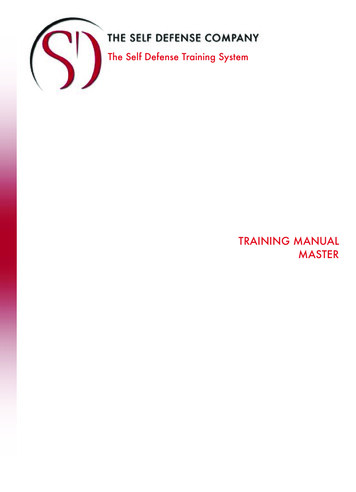
Chapter 111.1Basic S5 ProgrammingPage 1-1Basic S5 ProgrammingMethods of RepresentationIn STEP 5, a task definition can be formulated using three differentmethods of representation: Ladder diagram (LAD) Statement list (STL) Control system flowchart (CSF)The three methods of representation are discussed briefly in thefollowing subsections.Ladder DiagramIn ladder diagrams, the control task is defined using symbols similar tothose used in circuit diagrams. Programs can be entered, modified anddocumented as ladder diagrams. This method of representation alsoenables the output of dynamic status displays during on-line testing.Symbols used in ladder diagramsThe symbols used in ladder diagrams are similar to those used in circuitdiagrams. They are represented on the screen by unbroken lines and inprintouts by characters from the printer’s standard character font.Brackets (as per the standard “American” conventions) are used assymbols for NO and NC contacts, and parentheses as coil symbol for acontactor or relay:As in circuit diagrams, the “contacts” canbe interconnected both in series and inparallel. The symbol for the coil is locatedat the end of the “rung”TTI Trans Tech International 2013STEP 5 S5 for Windows Training
Page 1-2Basic S5 ProgrammingChapter 1Example: Representing a series connectionThe binary logic operations represented in a ladder diagram areinterconnecting structures of, NO and NC contacts in series and parallelcircuits. The coil symbol for a result assignment terminates the rung. It isthus possible to represent individual set/reset operations and conditionalblock calls (except for those relating to function blocks – these areautomatically displayed in Statement List presentation).A special case is the “connector”, which represents a result assignmentwithin a logic operation and is identified by the symbol like a coil.Example: Representing a “connector” in a ladder diagramComplex operations are represented as boxes. A box contains thesymbol identifying the relevant operation. “Rungs” lead to the functionsymbol’s inputs from the left, and “rungs” can be connected to thefunction symbol’s outputs at the right. “Complex” operations includeset/reset, timer, and counters and compare operations.STEP 5 S5 for Windows TrainingTTI Trans Tech International 2013
Chapter 1Basic S5 ProgrammingPage 1-3Examples of “complex” operations in ladder diagramsSet/reset operation:Timer operation:Compare operation:TTI Trans Tech International 2013STEP 5 S5 for Windows Training
Page 1-4Basic S5 ProgrammingChapter 1Counter operation:A function block call can also be called using LAD. S5 for Windows automatically switches into STL mode. If you prefer a graphicalpresentation you must switch to CSF presentation. A function block callmust be programmed in a separate segment.The number of the function block is shown within the Block callinstruction, the function block name and the names of the blockparameters (the function block’s “inputs” and “outputs”) are listed below.STEP 5 S5 for Windows TrainingTTI Trans Tech International 2013
Chapter 1Basic S5 ProgrammingPage 1-5Function Block call, graphical presentationThe number of the function block is specified above the box, the functionblock name and the names of the block parameters (the function block’s“inputs” and “outputs”) in the box.A function block call must be programmed in a separate segment.Even when ladder diagram has been selected as the representationmethod, it is still possible to enter basic STEP 5 operations whichcannot be represented in graphic form. To do so, you can switch to STLpresentation any time. This segment can subsequently be entered asstatement list. The system reverts to ladder diagram mode at thebeginning of the next segment.It is also possible to prevent S5 for Windows from switching into LADmode (if LAD is selected in the “Preference” settings). By entering “STL”at the beginning of a segment the segment will only be displayed in STL.TTI Trans Tech International 2013STEP 5 S5 for Windows Training
Page 1-6Basic S5 ProgrammingChapter 1Example for program representationSEGMENT 1Series-parallel circuit (1)SEGMENT 2Series-parallel circuit (2)The "rungs" are represented in segments. The segments are numberedautomatically. The first line is reserved to hold the segment header. Thesegment header may be up to 60 characters (selected in the“Preference” settings, miscellaneous tab).To enter a segment commentary of arbitrary length the “Commentsdisplay Window must be opened (Presentation Menu, DisplayComments).A new segment must be created for each “rung”. A segment maycontain only one “rung”.A block may comprise no more than 255 segments and no more than4091 statements.STEP 5 S5 for Windows TrainingTTI Trans Tech International 2013
Chapter 1Basic S5 ProgrammingPage 1-7Ladder diagram representation on the monitorThe screen space for ladder diagrams is subdivided into up to eight (8)columns and up to thirty (30) lines. The logic operation is shown in thefirst seven columns, the outputs in the eighth column.The contacts for a logic operation are drawn at the left screen margin(“rung”) or at a branch.Each field contains a contact symbol and the associated operandidentifier. The vertical links between the contacts (branches) are shownat the boundaries between the fields. Several fields may be required for“complex” function symbols.Segment Representation on the monitor:The screen can be rolled up. A rung (for an output, for instance) maycomprise as many as 30 (ladder diagram) lines.A “rung” corresponds to a “segment”.TTI Trans Tech International 2013STEP 5 S5 for Windows Training
Page 1-8Basic S5 ProgrammingChapter 1Symbolic ProgrammingSegment commentary and symbolic programming in a ladder diagramSymbolic operands (such as -On) may be used in place of absoluteoperand identifiers and parameters (such as I 5.0). An assignment list(Symbolic Table) must be generated, however, before symbolicoperands can be used in the program.To display symbolic operands the command “Symbolic Operands” fromthe Presentation Menu must be selected. To display the “SymbolicTable below the segment the command “Display Symbolic Table” fromthe Presentation Menu must be selected. This window displays theOperands in their absolute and symbolic form as well as an assignedcomment.Whenever an operand is marked in the segment the corresponding lineis displayed in the Symbolic Table window and the line has also a bluebackground.STEP 5 S5 for Windows TrainingTTI Trans Tech International 2013
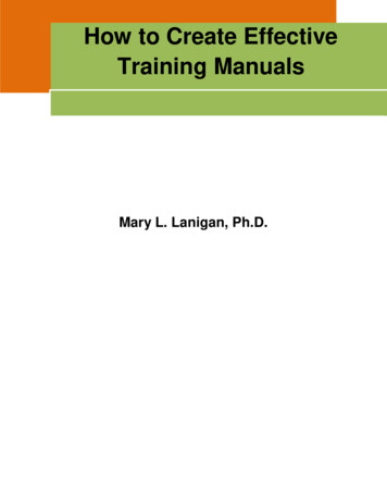
Chapter 1Basic S5 ProgrammingPage 1-9Statement List (STL)In a statement list, the control task is described in form of a list usingmnemonic (easily assimilated) abbreviations. The programminglanguage is based on a standard for programmable controllers.The program can be entered, modified and documented as statementlist. This method of representation also enables dynamic status displaysduring on-line testing.All operations available in the programming language (basic operations,supplementary operations and system operations) can be representedin statement list format.Structure of a statementA STEP 5 statement is the smallest independent unit of a program, andrepresents a processor directive. A statement comprises an operationcode (such as A for the AND operation) and an operand (for instanceI 1.7); an operand consists of an identifier (e.g. I for input) and aparameter (e.g. 1.7 for the 7th bit in the 1st byte).Example: Representing an AND operation“Complex” operations for which there are special symbols in the graphicrepresentation modes have no special symbols in a statement list; theyare written in the same manner as any other statement.TTI Trans Tech International 2013STEP 5 S5 for Windows Training
Page 1-10Basic S5 ProgrammingChapter 1Function Block Call (STL presentation)A function block call is also represented in list form, and can beprogrammed together with other statements, whereby the functionblock’s inputs and outputs (i.e. the block parameters) immediately followthe call statement.All basic operations of the STEP 5 programming language, which canbe represented in graphic form, can also be inputted as a statement listand outputted as control system flowchart or ladder diagram.An input, however, certain conventions must be observed as regardsauxiliary statements (such as “NOP 0”). Segments, which cannot berepresented in graphic form, are always outputted as statement list.In STL Presentation “rungs” do not have to be in separate segments.Several “rungs” can be combined into a segment. However such acombination of “rungs” in one segment cannot be displayed in a graphicmode (LAD, CSF presentation.Note:In STL Presentation there are no rules how to construct a segment. It iswise not to put to many lines of STL instructions into one segment.STEP 5 S5 for Windows TrainingTTI Trans Tech International 2013
Chapter 1Basic S5 ProgrammingPage 1-11Example for program representationThe logic operations are combined into segments. Several logicoperations can be represented in each segment. The segments arenumbered automatically.A 60-character segment header may be specified in the fist line after thesemicolon. Comments may be inserted in separate lines. Each commentline must start with a semicolon.Statement Comments may also be inserted after the STL command,separated by a semicolon.The segment end statement (“ *** “) and blank lines are separatestatements.A segment commentary of arbitrary length may be written between thenetwork header and the first statement to complete the documentation.A block may comprise no more than 255 segments. As many as 256MC5 statements may be programmed in each segment. A block isrestricted to no more than 4091 statements.TTI Trans Tech International 2013STEP 5 S5 for Windows Training
Page 1-12Basic S5 ProgrammingChapter 1Representation on the monitorThe STEP 5 statement begins with the operation code, followed by theoperand identifier and the parameter (both of which are left-aligned). Infunction blocks, a symbolic entry point (jump label – Tag) may be writtenat the left of the colon.To display the “Symbolic Table below the segment the command“Display Symbolic Table” from the Presentation Menu must be selected.This window displays the Operands in their absolute and symbolic formas well as an assigned comment.Whenever an operand is marked in the segment the corresponding lineis displayed in the Symbolic Table window and the line has also a bluebackground.STEP 5 S5 for Windows TrainingTTI Trans Tech International 2013
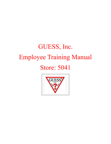
Chapter 1Basic S5 ProgrammingPage 1-13Control System FlowchartA control system flowchart uses symbols to describe the control task.The program can be input, modified and documented as control systemflowchart. This method of representation also enables the output ofdynamic status displays during on-line testing.Symbols used in control system flowchartsThe basic symbol used in control system flowcharts is the rectangularbox. On the monitor screen unbroken lines form these boxes whilestandard characters are used to represent them in printouts. The symbolin a box identifies the operation, which the box represents. The inputsare shown at the left, the outputs at the right of the function symbol.Example: Representing an AND operationThe binary logic operations represented in control system flowcharts arecombinations of AND and OR operations.A result assignment at the right of a logic operation always terminatesthat logic operation (see above), thus making it possible to representindividual set/reset operations and conditional block calls (except forthose relating to function blocks).In addition to logic operations AND and OR, there are also “complex”operations, i.e. set/reset, timer, counter and compare operations. Theseoperations are also represented by boxes. A symbol in each boxidentifies the relevant operation. The inputs for these operations areshown at the left, the outputs at the right of the boxes.A special case is the “connector”, which represents a result assignmentwithin a logic operation and is identified by a “ ” symbol in the box.TTI Trans Tech International 2013STEP 5 S5 for Windows Training
Page 1-14Basic S5 ProgrammingChapter 1Example: Representing a “connector” in a control system flowchartExamples for representing “complex” operations in a control systemflowchart.Set/reset operationCompare operationSTEP 5 S5 for Windows TrainingTTI Trans Tech International 2013
Chapter 1Basic S5 ProgrammingPage 1-15Timer operationCounter operationTTI Trans Tech International 2013STEP 5 S5 for Windows Training
Page 1-16Basic S5 ProgrammingChapter 1Calling a Function BlockA function block call can also be represented graphically.To do so, the number of the function block is specified above the boxand the function block name and the names of the block parameters(the function block’s “inputs” and “outputs”) in the box.A function block call must be programmed in a separate segment.Representing a function block callEven when the control system flowchart has been selected asrepresentation method, it is still possible to enter basic STEP 5operations which cannot be represented in graphic form. To do so, youcan switch to STL presentation any time. This segment cansubsequently be entered as statement list. The system reverts to controlsystem flowchart mode at the beginning of the next segment.It is also possible to prevent S5 for Windows from switching into CSFmode (if CSF is selected in the “Preference” settings). By entering “STL”at the beginning of a segment the segment will only be displayed in STL.STEP 5 S5 for Windows TrainingTTI Trans Tech International 2013
Chapter 11.2Basic S5 ProgrammingP
STEP 5 S5 for Windows Training TTI Trans Tech International 2013 The training documentation is for the personal use of the training participants only. The duplication of the training documentation for not licensed purposes, the passing on, utilization and communi