Transcription
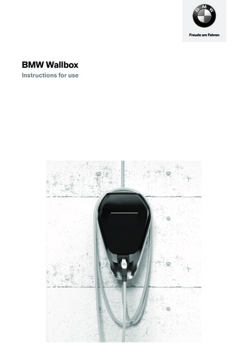
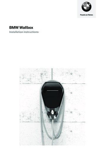
Freude am FahrenBMW WallboxInstallation instructions
5EN-USBMW WallboxInstallation instructions
BMW WallboxInstallation instructionsNOTESSafety instructionsIntended useAbout this manualScope of deliveryGuarantee9911111212OPERATIONDisplays and controls1313REQUIREMENTSGeneral requirements for selecting a locationRequirements for electrical connection141415INSTALLATIONPrerequisites for installationRecommended installation positionsNecessary installation spaceRemoving the casing coverRemoving the connector panel coverInstalling the WallboxConnecting the supply line1616161718192022ELECTRICSConnection overview (with open connector panel cover)2323SETTINGSDIP switch settings2424COMMISSIONINGGeneral commissioning processInstalling the connector panel coverInstalling the casing ent
6Technical dataStandards and guidelines3031DISPOSAL33SOFTWARE UPDATE34PRODUCT INFORMATION PAGE35INDEX37
ImprintBayerische Motorenwerke AktiengesellschaftMunich, Germanywww.bmw.comTranslation of the original installation instructionsCopyright 2019 BMW AG MunichThis documentation contains information protected by copyright. All rights are reserved, especially theright to copying and distribution. No part of the documentation may be reproduced or processed usingelectronic systems, copied, or distributed in any form whatsoever (by photocopying, scanning, or anyother process) without the written agreement of Bayerische Motorenwerke Aktiengesellschaft.EN-USViolations create an obligation to pay compensation.7
Information about this manualThis manual must be retained for the lifetime of the product.Read these instructions carefully and examine the device, so that you become familiar with it, beforeyou attempt to install, operate or maintain it. The following special messages may be displayed in thisdocumentation or on the device, in order to warn of possible risks or to indicate information whichclarifies or simplifies a process.The operating instructions should be used for the operation of the Wallbox and to explain errors.Keep these instructions safe for later use. The most current manuals can be downloaded from theInternet at https://charging.bmwgroup.com/web/wbdoc/.Symbols usedAt various points in the manual, you will find instructions and warnings of possible dangers. Thesymbols used have the following meanings:WARNINGMeans that death or serious injury may occur if the appropriate precautions are not taken.CAUTIONMeans that material damage or slight injury may occur if the appropriate precautions are nottaken.ATTENTIONMeans that material damage may occur if the appropriate precautions are not taken.ESDThis warning draws attention to the potential consequences of contact with electrostaticallysensitive components.NoteRefers to procedures which have no danger of creating injury.NoteYour BMW dealer will be happy to support you in finding a qualified installation partner.8
NOTESSafety instructionsRead the safety instructions carefully and examine the device, so that you become familiar with it,before you attempt to install operate or maintain it.WARNINGElectrical danger!Installation, commissioning, maintenance and retrofitting of the Wallbox must be carried outby appropriately trained, qualified, and authorized electricians(1), who bear full responsibilityfor complying with the applicable standards and installation regulations.Please note that additional overvoltage protector may be required by vehicles or nationalregulations.Comply with the country-specific connection and installation regulations.Before commissioning, confirm that all screwed and clamped connections are tight!The connector panel must never remain unattended while it is open. Fit the connectorpanel cover if you leave the Wallbox unattended.Do not undertake any unauthorized conversions or modifications of the Wallbox!Repair work on the Wallbox is not permitted, and may be carried out only by themanufacturer or by a specialist qualified for the task (replacement of the Wallbox)!Do not remove any markings such as safety symbols, warnings, performance rating plates,identification plates, or cable markings!The Wallbox does not have a power switch of its own! If present, the connector plug servesas a power cut-off device. Otherwise, the line protection in the building installation servesas a power cut-off device.Use only the plug (and not the cable itself) to pull the charger cable out of the plug holder.Ensure that the charger cable does not become mechanically damaged (kinked, trapped, ordriven over) and that the contact area does not come into contact with heat sources, dirt orwater.Do not insert your fingers into the plug connector.A visual inspection for damage should always be conducted before a charging process.For this, the contact area of the charging plug in particular should be checked for dirt andmoisture, the charger cable checked for cuts or abrasions to the insulation, and the cableoutlet of the Wallbox checked for firm seat.Persons who, on the basis of their specialist training, knowledge, and experience, as well asknowledge of the applicable standards, can assess the tasks assigned to them and recognize possibledangers.EN-US(1)9
WARNINGGrounding regulationsThis product must be grounded. If a malfunction or outage occurs, then grounding providesthe electrical current with a path of least resistance, in order to reduce the risk of an electricshock. This product is equipped with a cable which has a device grounding conductor and agrounding plug. The plug must be inserted into a suitable outlet which is correctly installed andgrounded in compliance with all local regulations and requirements.WARNING – Incorrect connection of the device grounding conductor can result in electricshock. Consult a qualified electrician or service technician if you are not sure whether theproduct is correctly grounded. Do not make any modifications to the plug supplied withthe product – if it does not fit the outlet, then have a suitable outlet installed by a qualifiedelectrician.ATTENTIONNever clean the Wallbox using a water jet (garden hose, high pressure cleaner, etc.)!Ensure that the Wallbox is not damaged by inappropriate handling (casing cover, internalparts, etc.).If it is raining or snowing, and the Wallbox is mounted outdoors, do not open the connectorpanel cover!Risk of breaking the plastic casing!- Do not use countersunk screws for fastening!- Do not tighten the attachment screws forcefully.- The installation surface must be completely even (max. 1 mm difference between contactand/or attachment points). The casing must not be bent.Information for specialists who open the device:Risk of damage! Electronic components may be destroyed by being touched!Before working with assemblies, carry out an electrical discharge by touching a metallic,grounded object!Failure to comply with the safety instructions may result in danger to life, injuries, and damage to thedevice! The manufacturer assumes no liability for claims resulting from this!10
Intended useThe Wallbox is a charging station for indoor and outdoor use, by means of whichelectric or plug-in hybrid vehicles can be charged. It is not permitted to connect other devices, e.g.electrical tools! The Wallbox is intended to be fitted to a wall or a mounting pillar. For installation andconnection of the Wallbox, the applicable national regulations must be complied with.In all cases, intended use of the device includes compliance with the environmental requirements forwhich this device was developed.The Wallbox was developed, manufactured, tested, and documented in compliance with the applicablesafety standards. Therefore, if instructions provided for intended use and the safety instructionsare complied with, under normal circumstances no risks arise from the product in terms of materialdamage or the health of persons.This device must be grounded. In the case of a fault, the ground connection reduces the risk of anelectric shock. It is fitted with a connector plug with ground connection, or else optionally has a fixedconnection and is connected to a protective conductor. The equipment connector plug must beinserted into the socket which is provided for the purpose and which was installed in compliance withlocal regulations.The instructions in this manual must be followed exactly. Otherwise, sources of danger could becreated, or safety devices could be made ineffective. Regardless of the safety instructions provided inthis manual, the safety and accident prevention regulations corresponding to the individual applicationcase must be complied with.Because of technical or legal restrictions, not all variants/options are available in all countries.About this manualThis manual and the functions described are valid for devices of the type:BMW WallboxThis manual is intended exclusively for qualified personnel. These are persons who, on the basis oftheir specialist training, knowledge, and experience, as well as knowledge of the applicable standards,can assess the tasks assigned to them and recognize possible dangers.Please refer to the operating instructions for the device for information and instructions on operation.11EN-USThe images and explanations in this manual are based on a typical model of the device. The model ofyour device may be different from this.
Scope of deliveryDescriptionQuantityWallbox1xInstallation instructions1xOperating instructions1xDrilling template1xDouble membrane nipple M32 or ¾" NPT (clamping range 14-21 mm)1xDouble membrane nipple M16 (clamping range 7-12 mm)2xAttachment set for wall installationPlug for M8, Fischer UXR-104xWafer-head screw4xGuaranteeBMW Service will provide information on the currently applicable guarantee terms. However, the caseslisted below are excluded from the guarantee.Defects or damage caused by installations which were not carried out as per the requirements inthe BMW Wallbox installation instructions.Defects or damage caused because the product was not used as per the requirements in theBMW Wallbox operating instructions.Costs and damage of repairs not performed by a specialized electrician authorized by a BMWsales outlet or authorized contracted service workshop.12
OPERATIONDisplays and controlsFunctions:Charging of electric or plug-in hybrid vehiclesEN-US1 Status LED2 Holder for charger cable connector3 Charger cable connector13
REQUIREMENTSGeneral requirements for selecting a locationThe Wallbox was designed for indoor and outdoor use. It is therefore necessary to make arrangementsfor the installation location and protection of the device.Take into account the locally applicable requirements for electrical installations, measures for fireprevention, and accident prevention regulations, as well as escape routes at the location.You must not install the Wallbox at locations:Which are used as escape and emergency routes.Which are located in potentially explosive zones (hazardous location).In which the Wallbox will be exposed to ammonia or ammonia gases (e.g. in or adjacent tostables).In which falling objects (e.g. suspended ladders or car tires) could damage the Wallbox.In which the Wallbox is situated directly in pedestrian traffic and where people could trip overinserted charger cables.In which direct water jets could strike the Wallbox (e.g. from adjacent car wash installations,high pressure cleaners, garden hoses).In which the installation surface is of insufficient strength to withstand the mechanical loads.If possible, install the Wallbox protected from direct rainfall, in order to avoid weathering, icing up,damaging by hail or similar.If possible, install the Wallbox protected from direct sunshine, in order to prevent the reduction ofthe charging current or the interruption of charging because of excessive temperatures of Wallboxcomponents.Comply with the permitted environmental conditions, see section Technical data.Comply with the nationally applicable installation standards, e.g. NFPA 70 and CSA C22.1, andcomply with the nationally and regionally applicable installation standards and regulations, e.g.Electric Code, Building Code, Residential Code, and Fire Code.NoteFor an installation exposed to the weather, e.g. on an open air parking lot, this can result inan impermissible temperature excursion which reduces the charging current specification to16 A.14
Requirements for electrical connectionAs delivered, the maximum charging current for the Wallbox is set to 32 A.Pre-installed connection cableAs delivered, the Wallbox is provided with a pre-installed connection cable with a NEMA 6-50p plugwhich can be inserted into an appropriate socket.The following safety measure must be installed:EN-USBranch circuit breaker: max. 40 A15
INSTALLATIONNoteAs delivered, the maximum charging current for the Wallbox is set to 32 A.Prerequisites for installationComply with the locally applicable installation guidelines.The electrical connection (NEMA 6-50p socket) must be prepared.Acclimatization: If the temperature difference between transportation and installation locationis greater than 15 C, then the Wallbox should be allowed to acclimatize for at least two hourswithout being opened.Under some circumstances, damage from condensate water may not arise until at some pointafter the installation.Ideally, the Wallbox should be left at the installation location for a few hours in advance. If this isnot possible, then the Wallbox should not be stored overnight in the open air or in a vehicle at lowtemperatures ( 5 C).List of toolsThe following tools are needed for the installation:Torx screwdriver T40Recommended installation positionsWhen selecting the installation position, please take into account the position of the chargingconnection on your vehicle and the usual direction of parking. Examples:BMW i31 Recommended installation position2 Alternative installation position16BMW/MINI PHEV
Necessary installation spaceThe installation space specified below (hatched area) ensures convenient installation and operation ofthe Wallbox. If several Wallboxes are installed next to each other, then a separation of at least 200 mm(8") must be maintained between the Wallboxes.NoteThe installation height must be complied with, in order to fulfill the requirements for indoor andoutdoor use.EN-USDimensions in millimeters (inches)17
Removing the casing cover1. On the underside of the Wallbox, push thetwo locking mechanisms 1 of the casing coverupwards.The casing cover should spring outwards alittle at the bottom.2. On the underside, swing the casing coverforwards a little 2.3. Now unhook the casing cover upwards 3.NoteIn order to avoid scratches or otherdamage, store the casing cover in itspackaging.18
Removing the connector panel coverNoteIt is necessary to remove the connector panel cover only if the setting of the DIP switchesneeds to be changed, or if the Wallbox is to be permanently connected to the power network.1. Release the four screws with which theconnector panel cover 1 is mounted.ESDRisk of damage! Electronic components may be destroyed by being touched!Before working with assemblies, carry out an electrical discharge by touching a metallic,grounded object!2. Remove the connector panel cover. Theconnector panel 2 is now accessible.WARNINGEN-USThe cover of connection area 3 for the line voltage may be removed only by a trainedelectrician.19
Installing the WallboxThe attachment material supplied is suitable for concrete, tiling, and wood (without the use of plugs). Ifthe substructure is not one of the above, then a suitable type of attachment must be selected.NoteIf the substructure is not one of the above, then the attachment materials must be providedby the customer. It is essential that the device is fitted correctly, and this is outside theresponsibility of the device manufacturer.Installation preparationsDrilled holesNoteComply with the installation height.Upper edge of the drilling template 59 to 67 inches.1. Use the provided drilling template and a spiritlevel to mark the locations for the four drilledholes 1 to 4.2. Drill the attachment holes.3. Insert the plugs.Top attachment screws1. Screw in the two top wafer-head screwsuntil the remaining distance from the wall is 0.79 inches.1 Wall2 Plug3 Drilled hole4 Wafer-head screw20
Installation on cavity wallsFor installation on cavity walls, at least twoattachment screws, e.g. 1 and 2, must beattached to one of the wall's supporting elements.For the other attachment screws, special cavitywall plugs must be used.NoteWhen installing on a cavity wall, you mustensure specifically that the structure hassufficient load bearing capacity.Attaching the Wallbox1. Hang the Wallbox from the two top wafer-headscrews 1 and 2.NoteEnsure that the supply line is correctlylaid on the reverse side, and that it is nottrapped.2. Tighten wafer-head screws 1 and 2.3. Then attach the Wallbox using the two lowerwafer-head screws 3 and 4.EN-US4. For safe storage, wind the charger cablearound the Wallbox, see operating instructions.21
Connecting the supply lineAs supplied, the Wallbox is equipped with a preinstalled connection cable (1).This can be connected into an appropriate socket,using a NEMA 6-50p plug.If required, the supply line can also be convertedby a specialist into a permanent connection to anexisting domestic installation, but the nationallyapplicable regulations must be complied with.22
ELECTRICSConnection overview (with open connector panel cover)DSW1 DIP switch for configurationX3 Diagnostics connection, RJ45T1 Service buttonX5 USB connectionDSW2 DIP switchLED Status LED (internal)X4 Ethernet1 connection, LSA terminalsShd Shield connection for Ethernet1connection terminalsX2 RS485 connectionATTENTIONThe X3 diagnostic connection is suitable only for error analysis and must not be used toconnect the device to a network.NoteEN-USThe connection overview shows all options of the device, but the legend only lists the availableoptions. If necessary, not all connections are available for your device variant.23
SETTINGSDIP switch settingsNoteChanges to the DIP switch settings take effect only after a restart of the Wallbox! To do this,press the Service button until the first signal tone sounds (approx. two seconds). Alternatively,you can also switch the supply voltage off and on again.NoteSwitches which are not described here must be left in the OFF position.DIP switchesThe DIP switches are used for addressingand configuring the Wallbox, and are locatedunderneath the connector panel cover.DSW1: Configuration, DIP switch upperDSW2: Addressing, DIP switch lowerDIP switch - exampleFor more detailed explanation, the illustrationshows the position of the DIP switches for the ONand OFF states.24
Maximum charging current (DSW1)The following DIP switches can be used to set a maximum value for the charging current. Thismaximum value applies to each connected phase individually and not as a sum value for all phasestogether. The current specification is transmitted to the vehicle (Control Pilot Duty Cycle). It is onlypossible to set a maximum value, which is less than or equal to the operating current defined on thetype plate.DIP switchIllustrationDSW1.6DSW1.7DSW1.80AONONON10 AOFFOFFOFF13 AONOFFOFF16 AOFFONOFF20 AONONOFF25 AOFFOFFON32 AONOFFONEN-USCurrent25
COMMISSIONINGGeneral commissioning processSwitch on the supply voltage. 15-20 seconds after the self-test, the status LED (LED strip) mustlight up blue.Carry out the prescribed initial testing as per locally applicable guidelines and laws.Install the casing cover, see section Installing the casing cover.Installing the connector panel coverNoteConfirm that a current version of the software is available before you install the connector panelcover. For further information, see section SOFTWARE UPDATE.NoteThe Wallbox must not be used permanently if this cover is absent or damaged. Alternativecovers are not permitted.Attachment bolts1. Replace the connector panel cover 1.2. Attach the connector panel cover again usingthe four bolts.26
Casing marking1. Tighten the four bolts until the casing markingsat right and left on the connector panel coverclose flush with the casing.2. The connector panel cover must be correctlysealed by the casing.EN-USFor self-tapping bolts, an increased torqueapplication is required: 2.58 ft·lb.27
Installing the casing coverNoteThis cover is not essential for the safe operation of the Wallbox.Attaching the casing cover1. Attach the casing cover at the top, and ensurethat the hooks of the casing cover are correctlyinserted 1.2. Press the cover downwards, and then tilt thecasing cover 2 towards the back.The casing cover must slide into the lowerguides with very little resistance.ATTENTIONEnsure that the casing cover sits correctlyinto the casing guide on all sides. Only asmall uniform gap should be present.Locking mechanisms1. Press the lower part of the casing cover ontothe Wallbox until the locking mechanisms 1engage fully.28
MISCELLANEOUSDimensionsEN-USDimensions in millimeters29
Technical dataElectrical dataCable feed:Surface or flush-mountedConnection cross-section:As per the branch circuit breakerSupply terminals:Connection line:- AWG (min.-max.): 24 – 6Temperature rating for supply terminals:105 C (221 F)Rated current (configurable connection values):10 A, 13 A, 16 A, 20 A, 25 A, or 32 A1-phase (3 lines)Mains voltage:120/240 V or 120/208 V Y or 127/220 V c.a.Mains frequency:60 HzOvervoltage category:III in accordance with UL 840Branch circuit breaker (control cabinet):Max. 40 AFault current monitoring:CCID20Ventilation during charging:Not supportedProtection class:IIP protection class for device/type rating:IP54/Type 3RProtection against mechanical impact:IK08Mechanical dataDimensions (W x H x D):15.7 x 25.67 x 7.95 inches (excluding plug)Weight:approx. 10 kg (depending on variant)Installation (stationary):On the wall or mounting pillar30
Ambient conditionsUsage:Indoor and outdoorOperating temperature range-30 C to 50 C (-22 F to 122 F)without direct sunlightTemperature behavior:This is not a safety device, merely an operatingfunction. The specified operating temperaturerange must be complied with.Within the specified operating temperatureranges, the device provides the charging currentcontinuously.To increase the charging availability, the chargingcurrent specification is reduced to 16 A in theevent of prohibited exceeding of temperature.A further consequence may be the shut-off ofthe charging process. After cooling, the chargingprocess is continued, and the charging currentspecification is increased again.Temperature range for storage:-30 C to 80 C (-22 F to 176 F)Rate of temperature change:max. 0.5 C/min (max. 32.9 F/min)Permissible relative air humidity:5 % to 95 % non-condensingAltitude:max. 6560 ft above sea levelStandards and guidelinesFCC Title 47, Part 15Digital Device Class BNEC Article 625Electric vehicle charging systemsEN-USNational regulations (USA)National regulations (Canada)CE Code CSA C22.1 No. 280Electric Vehicle Supply EquipmentICES-003Class B31
Recognized standardsUL 2594CSA C22.2 No. 280NMX-J-677-ANCEElectric vehicle supply equipmentUL 2231-1CSA C22.2 No. 281.1NMX-J-668/1-ANCEPersonnel protection systems for electric vehicle(EV)Supply circuits: General requirementsUL 2231-2CSA C22.2 No.281.2NMX-J-668/2-ANCEPersonnel protection systems for electric vehicle(EV)Supply circuits: Particular requirements forprotection devices for use in charging systemsUL 991Tests for Safety-related controls employing solidstate devicesUL 1998Software in programmable componentsUL 61010CSA C22.2 No. 107.1Electrical Equipment For Measurement,Control, and Laboratory Use; Part 1: GeneralRequirements32
DISPOSALAfter correctly decommissioning the device, please have the device disposed of byService or else in compliance with all currently applicable disposal regulations.EN-USDisposal informationThe symbol of the "crossed-out" waste bin means that electrical and electronicdevices, including accessories, must be disposed of separately from generalhousehold garbage. Instructions are to be found on the product, in the instructions foruse, or on the packaging.The materials can be recycled according to their designation. Through re-use,material recycling, or other forms of recycling old equipment, you will be making animportant contribution to the protection of our environment.33
SOFTWARE UPDATEThe software for the Wallbox can be updated via the USB connection inside the device. For access tothe USB connection, the casing cover and the connector panel cover must be removed.Follow the details in the instructions for updating the software.The latest software and the corresponding instructions can be downloaded from theInternet at https://charging.bmwgroup.com/web/wbdoc/. A new software version may,for example, take into account modified standards, or improve the compatibility withnew electric or plug-in hybrid vehicles.34
PRODUCT INFORMATION PAGEThis product is UL-certified.It complies with the applicable UL, CSA, and ANCE standards forNorth America, Canada, and Mexico. For further information, seehttps://charging.bmwgroup.com/web/wbdoc/.FCC INFORMATIONThis device complies with part 15 of the FCC Rules. Operation is subject to the following twoconditions:(1) This device may not cause harmful interference, and(2) this device must accept any interference received, including interference that may causeundesired operation.ATTENTION:Changes or modifications which were not expressly approved by the responsible authority mayimpede the right to use the device.NOTE:This device was tested, and it complies with the limits for a digital device of class B as per part15 of the FCC regulations. This limit is intended to provide appropriate protection against harmfulinterference in a residential situation. This device generates and uses high frequency energy,and if it is not installed in compliance with the instructions, it can result in interference to radiocommunication. However, there is no guarantee that there will be no interference in a specificinstallation. If this device causes interference to radio or television reception (this can be determinedby switching the device off and on), then the user should attempt to prevent the interference throughone or more of the following measures:Align the reception antenna differently.- Increase the distance between device and receiver.- Connect the devices to a different power circuit than the one to which the receiver is connected.- Request assistance from the dealer or from an experienced radio/television technician.EN-USCANADAThis class B digital apparatus complies with Canadian ICES-003.35
This product is NOM-certified.MEXICOOperation is subject to the following two conditions: (1) This device may not cause harmfulinterference, and (2) this device must accept any interference received, including interference thatmay cause undesired operation.36
INDEXAAbout this manual. 11Attaching the Wallbox. 21BBMW Wallbox overview. 13CCommissioning. 26Connecting the supply line. 22Connection overview (with open connector panel cover). 23DDIP switch settings. 24Disposal. 33GGeneral requirements for selecting a location. 14IImprint. 7Installation. 12, 16Installation prerequisites. 16Installing the casing cover. 28Installing the connector panel cover. 26Installing the Wallbox. 20Intended use. 11LList of tools.
the BMW Wallbox installation instructions. Defects or damage caused because the product was not used as per the requirements in the BMW Wallbox operating instructions. Costs and damage of repairs not performed by a specialized electrician authorized by a BMW sales outlet or au