Transcription
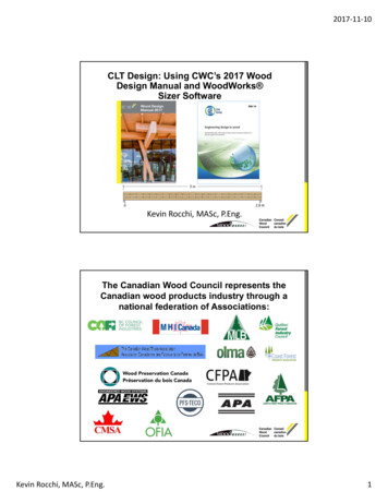
2017‐11‐10CLT Design: Using CWC’s 2017 WoodDesign Manual and WoodWorks Sizer SoftwareKevin Rocchi, MASc, P.Eng.The Canadian Wood Council represents theCanadian wood products industry through anational federation of Associations:Kevin Rocchi, MASc, P.Eng.1
2017‐11‐10CWC produces and communicates technicalinformation to architects, engineers, builders, andother designers on how to use wood in buildings froma structural, fire, and sustainability design perspective.www.cwc.caPresentation Outline1. CSA O86‐14 Overview2. Where are we with CLT Design in CanadianCodes?3. How are wood structures Taller than 6Storeys being built?4. CWC CLT Design Tools? Wood Design Manual 2017 Woodworks SizerKevin Rocchi, MASc, P.Eng.2
2017‐11‐10CSA O86-14 Update 1 Overview Published in June 2016 Clause 8 (Gravity loadDesign of CLT) Clause 11.9 (LateralLoad Design of CLT) Clause 12 (CLTConnection Design) Provides Guidance forCLT Platform framedLFRS up to 6 StoreysKR1Where are we with CLT Design inCanadian Codes?Provincial or Part 4 Based Referenced NumberNational CodeonCSA O86 of StoreysNBC 2010CSA O86‐094BCBC 2012NBC 2010CSA O86‐096ABC 2014NBC 2010CSA O86‐096OBC 2012NBC 2010CSA O86‐096*RBQ 2010NBC 2010 CSA O86‐14*6*NBC 2015CSA O86‐146*Provincial Code Amended to allow more storeys or updated standardKevin Rocchi, MASc, P.Eng.3
2017‐11‐10How are wood structures taller than 6storeys being built?Alternative SolutionsNBC 2015 Clause 1.2.1.1.1)b)CSA O86‐14 Clause 4.3.2Typically more expensive to achieve alternative solutionsHow are wood structures taller than 6storeys being built?18 Storey Brock CommonsDemonstration Project(Vancouver)ooooGravity: 2‐way CLT Floorsand SCL/Glulam ColumnsLFRS: ConcreteShearwallsUtilized Site SpecificCode Amendment toallow for an 18 StoreyWood StructureUBC Campus has its ownBuilding DepartmentPhotos Courtesy of Acton Ostry Architect Inc. (website)Kevin Rocchi, MASc, P.Eng.4
2017‐11‐10How are wood structures taller than 6storeys being built?12 1 Storey OrigineDemonstration Project(Quebec City)oooGravity: Glulam postand beam, CLT Wallsand FloorsLFRS: CLT Shearwallsand DiaphragmsAlternative SolutionOrigine (from the package NORDIC‐CWC‐2017.zip): Nordic Structures Stéphane GroleauHow are wood structures taller than 6storeys being built?8 Storey Abora Condos (Montreal)oooGravity: Glulam post and beam, CLT Wallsand FloorsLFRS: CLT Shearwalls and DiaphragmsAlternative Solution using Quebec GuideArbora (from the package NORDIC‐CWC‐2017.zip): Nordic Structures Adrien WilliamsKevin Rocchi, MASc, P.Eng.5
2017‐11‐10How are wood structures taller than 6storeys being built?Quebec Guide for MassTimber Construction upto 12 Storeys Pre‐approvedAlternative Solution forMass Timber includingCLT for up to 12 Storeys RBQ is the only bodywhich reviews andaccepts alternativesolutions in Quebec Other Provinces ‐required to proveAlternative Solutionswith local AHDHow are wood structures taller than 6storeys being built?Why is the Tall Wall Guide Limited to 12Storeys? Most cities don’t build taller than 12 Wood Compression Perpendicular to GrainFailureThe Case for Tall WoodBuildings (2012)By MGB Architects Design, EquilibriumConsulting, LMDG Lft.And BTY GroupKevin Rocchi, MASc, P.Eng.Photo Courtesyof Acton OstryArchitect Inc.(website)6
2017‐11‐10How are wood structures taller than 6storeys being built?What options do I have outside Quebec? Wait for Possible Code Changes to theNBC (2020?) Ontario Ministry of Natural Resourcesand Forestry Ontario Tall Wood BuildingReference: A Technical Resource forDeveloping Alternative Solutionsunder Ontario’s Building Code November 2017How are wood structures taller than 6storeys being built?New NRCan Demonstration Project Funding: Facilitate revisions to the 2020 and 2025 NBC toallow wood buildings up to 12 stories. A Call for Expressions of Interest closes inDecember 2017 Visit gcwood.caON specific projects received MIGHT be evaluatedconcurrently by MNRF and NRCanBased on updated climatic models, Climatic andSeismic Data is likely to change in NBC 2020Why stop at 12 Storeys when wood componentswork within an 18 Storey Building?Kevin Rocchi, MASc, P.Eng.7
2017‐11‐10Wood Design Manual 2017 CSA O86‐14 Update 1 and 2 O86 Structural CommentaryWood Design Manual 2017Chapter 2 Bending Members Several orthogonal layers of lumber, laid flatwise andglued (Typical 3 to 9 alternating layers).Thickness usually ranges between 100 mm and 300 mm(as thick as 500 mm can be produced).Width usually ranges from 1.2 to 3 m, Length can rangefrom 5 to 19.5 mPanel Size limited by manufacturers’ press andtransportation regulations.PhotosCourtesy of FPICLT HandBookKevin Rocchi, MASc, P.Eng.8
2017‐11‐10Wood Design Manual 2017Chapter 2 Bending Members CSA O86 includes 5 Stress Grades (E1, E2, E3, V1 and V2).o E – MSR, V‐ visually graded lumber (Refers to grade ofLongitudinal layers)o Transverse layers consist of lower grade visually gradedlumberLongitudinal LayersTransverse LayersWood Design Manual 2017Chapter 2 Bending MembersKevin Rocchi, MASc, P.Eng.9
2017‐11‐10Wood Design Manual 2017Chapter 2 Bending MembersManufacturer CLT Layups and Properties British Columbia EngineersResponsible forDesign Grades – E1, V2 SPF MSR and visualgrade D.Fir‐LCrosslam CLT Technical Design Guide(www.structurlam.com)Wood Design Manual 2017Chapter 2 Bending MembersManufacturer CLT Layups and Properties Quebec Nordic EngineersComplete Design(Exceptions) Grades – E1 Black SpruceMSRNordic Structures Design Properties, Nordic X‐lam(www.Nordic.ca)Kevin Rocchi, MASc, P.Eng.10
2017‐11‐10Wood Design Manual 2017Chapter 2 Bending Members*Similar Equations for Minor Strength AxisWood Design Manual 2017Effective Bending Stiffness and in‐plane shear rigidityKevin Rocchi, MASc, P.Eng.11
2017‐11‐10Wood Design Manual 2017Chapter 2 Bending MembersWood Design Manual 2017Chapter 2 Bending MembersKevin Rocchi, MASc, P.Eng.12
2017‐11‐10Wood Design Manual 2017Chapter 2 Bending MembersWood Design Manual 2017Chapter 2 Bending MembersKevin Rocchi, MASc, P.Eng.13
2017‐11‐10Wood Design Manual 2017Wood Design Manual 2017Chapter 2 Bending Members5‐ply, V1 stress grade (h 175 mm): Kevin Rocchi, MASc, P.Eng.14
2017‐11‐10Wood Design Manual 2017Chapter 2 Bending MembersWood Design Manual 2017Chapter 2 Bending MembersCLT Stiffness Elastic deflection due to Short and Standard term loads Elastic deflection due to long term loads Creep Adjustment factor ( 2.0)Uniform Loads:Kevin Rocchi, MASc, P.Eng.Concentrated Loads:15
2017‐11‐10Wood Design Manual 2017Panel Selection TablesWood Design Manual 2017Chapter 2 Bending MembersFrom the floor panel selection tableD 1.5 kPa and L 2.4 kPa:For V1, 5‐plyAllowable span 6.63 m 6 m What if the floor is sensitive tovibration? (e.g. Residential Floor)Kevin Rocchi, MASc, P.Eng.16
2017‐11‐10Wood Design Manual 2017Chapter 2 Bending MembersCLT Vibration DesignWood Design Manual 2017Panel Selection TablesKevin Rocchi, MASc, P.Eng.17
2017‐11‐10Wood Design Manual 2017Chapter 2 Bending MembersWhat if the floor is sensitive tovibration? (e.g. Residential Floor)From the vibration selection table:For V1, 5‐plyAllowable span 5.27 m 6 m XUse 7‐ply V1 ‐ 6.58 mWood Design Manual 2017Chapter 2 Bending MembersNail‐Laminated Timber Panels (NLT) Consists of lumbermembers stacked onedge and spikedtogether CSA O86‐14 Clause6.5.11.1 Nail‐LaminatedDecking Treated similarly toPlank Decking in CSAO86Photo Courtesy of StructurcraftKevin Rocchi, MASc, P.Eng.18
2017‐11‐10Wood Design Manual 2017Chapter 2 Bending MembersNail Laminated Timber Panels (NLT) “Mill construction” Over 43 buildings (5storey and greater inheight) exist in Toronto NLMA published theHeavy Timber MillConstruction Buildings(1916) Guidance on the Designof NLT existed in firstNBC (1941) and the firstCSA O86 (1959)Photo Courtesy of FPIWood Design Manual 2017Chapter 2 Bending MembersNail Laminated Timber Panels (NLT)Kevin Rocchi, MASc, P.Eng.19
2017‐11‐10Wood Design Manual 2017Chapter 2 Bending MembersNail Laminated Timber Panels (NLT)Wood Design Manual 2017Chapter 2 Bending MembersGlued‐Laminated Timber Panels (GLT) Treat the system as a built‐up beam consisting of No.2 grade lumber No increased strength for higher grades of GlulamKevin Rocchi, MASc, P.Eng.20
2017‐11‐10Wood Design Manual 2017Chapter 2 Bending MembersGlued Laminated Timber Panels (GLT)Wood Design Manual 2017Chapter 3 Compression MembersKevin Rocchi, MASc, P.Eng.21
2017‐11‐10Wood Design Manual 2017Chapter 3 Compression Members 43Wood Design Manual 2017Chapter 3 Compression MembersIeff, Aeff and reff for CLT Panels Major andMinor Strength AxisKevin Rocchi, MASc, P.Eng.22
2017‐11‐10Wood Design Manual 2017Chapter 3 Compression MembersWood Design Manual 2017Chapter 5 Combined Bending and Compression MembersPΔKevin Rocchi, MASc, P.Eng.23
2017‐11‐10Wood Design Manual 2017Chapter 5 Combined Bending and Compression Members(Pf/Pr) (Mf/Mr)PΔ 1.0700600Pf (kN)5004000.4Pr300200Determinew’r based on Mf100001020Mf (kNm)3040Selection Tables: Based on variouslevels Pr (10 –80%) Provides factoreduniform arealoads, w’r (kPa)which result when(Pf/Pr) (Mf/Mr)PΔ 1.0Wood Design Manual 2017Chapter 5 Combined Bending and Compression Memberse 0w’rKevin Rocchi, MASc, P.Eng.PfPfe d/6w’rPfe d/2w’r24
2017‐11‐10Wood Design Manual 2017Chapter 5 Combined Bending and Compression MembersWood Design Manual 2017Chapter 6 Bearing DesignGeneral Bearing CheckCritical Bearing CheckKevin Rocchi, MASc, P.Eng.25
2017‐11‐10Wood Design Manual 2017Chapter 6 Bearing DesignWood Design Manual 2017Chapter 6 Bearing DesignGeneral Bearing Check*Load on floorpanel adds 15 kN Critical Bearing Check Critical Bearing GovernsKevin Rocchi, MASc, P.Eng.26
2017‐11‐10Wood Design Manual 2017Chapter 7 Connection DesignCross Lamination EffectLongitudinal Different layers are loaded atFLayersdifferent angles due to crosslamination Causes decrease in strengthcompared with common wood‐to‐wood connections (observedthrough testing) Adjustment factor for CLT(Jx 0.9)Transverse Layers O86 covers, nails, wood screws,bolts and lag screwsWood Design Manual 2017Chapter 7 Connection Design ‐ Boltso Load // to major strengthdirection (i.e., outer layer)5010.01o Load perp. to majorstrength direction2210.01 Check Brittle FailureModes for uncommonbolt configurationsKevin Rocchi, MASc, P.Eng.27
2017‐11‐10Wood Design Manual 2017Chapter 7 Connection Design ‐ Bolts Check Brittle Failure Modes for uncommonbolt configurations See O86 for guidanceWood Design Manual 2017Chapter 7 Connection Design – Bolts105 mmthick V2stressgrade CLTHow Many ¾” bolts per along a1 m wide panel when thefactored load is 30.9 kN?Kevin Rocchi, MASc, P.Eng.28
2017‐11‐10Wood Design Manual 2017Chapter 7 Connection Design – Bolts30.9 kN / 16.2 kN 1.91Therefore use 2 – 3/4” Bolts per mWood Design Manual 2017Chapter 7 Connection Design – Nails and Wood ScrewsLateral resistance2501.1100.0110.010.67 for nailing into end grain,or make sure side grain penetration occursWithdrawal resistance.16.459.nailsscrews0.9 for CLTKevin Rocchi, MASc, P.Eng.29
2017‐11‐10Wood Design Manual 2017Chapter 7 Connection Design – Nails and Wood ScrewsWood Design Manual 2017Chapter 7 Connection Design – Nails and Wood ScrewsNotes:4. Table based on Jx 1.0, applicable toall wood products except CLT. For CLTmultiply the values in the Table by 0.9.Kevin Rocchi, MASc, P.Eng.30
2017‐11‐10Wood Design Manual 2017 Chapter 8 Lateral Load DesignStructure type Platform constructionDesign Considerations Rely on capacity design procedures moderate or high ductility connections forenergy dissipation at specified locations other connections are designed with sufficientover-strength to be non-dissipative connectionsRd 2.0, Ro 1.5CLT Panels Act as rigid bodies O86 does not provide guidance on in-plane bendingand shear strength and stiffness Research has shown it is unlikely to govern Prudent to check (Manufacturer)Wood Design Manual 2017 Chapter 8 Lateral Load DesignIntended rigid body motion Rocking or rocking andsliding in combination If sliding only RdRo 1.3Aspect Ratio 1:1 to 1:4 If less than 1:1 use RdRo 1.3Height limit In high seismic zones, 20 m; other seismiczones, 30 m Same as nailed wood-based shearwallIrregularity restriction Type 4 or 5 irregularities not allowedKevin Rocchi, MASc, P.Eng.31
2017‐11‐10Wood Design Manual 2017Chapter 8 Lateral Load Design Energy-dissipative connections (Fuse): connections joining the walls to the foundation or the floorpanels below, vertical joints between the wall panels discrete hold-downs Non-dissipative connections (Over-Strength): continuous steel rods floor to supporting wall joints connections between perpendicular walls Factored resistance of non-dissipative connectionsrequired to be higher than the strength demand that isinduced on them when the energy-dissipativeconnections reach their 95th percentile of ultimateresistance under cyclic loading.Wood Design Manual 2017Chapter 8 Lateral Load Design In the case of a monolithic CLT wall, the analyticalprocedure is simple and only based on equilibriumFKinematic Mode –Rocking (Rd 2.0,Ro 1.5)For Simplicity – No nsNon‐dissipativeconnections: AngleBracketsPhoto Courtesy of FPIKevin Rocchi, MASc, P.Eng.32
2017‐11‐10Wood Design Manual 2017Chapter 8 Lateral Load DesignF 16 kNHDF F x H / L16 kN x 3m/3m HDF 16 kNH 3mHDFL 3mPhoto Courtesy of FPIWood Design Manual 2017Chapter 8 Lateral Load DesignF 16 kNHDcapHDF 16 kNCustom HD¾” bolt, single 6 mmsteel plate,105 mmthick panelHDcap 16.2 kN 16 kN Photo Courtesy of FPIKevin Rocchi, MASc, P.Eng.33
2017‐11‐10Wood Design Manual 2017Chapter 8 Lateral Load DesignHDcap 16.2 kN Based on 5th%ileCapacity (CSA O86) Need 95th%ileHDcapcapacity to tive connections: ConnectorHold‐downsManufacturerNon‐dissipative connections:Angle BracketsWood Design Manual 2017Chapter 8 Lateral Load Design Two Panel CLT wall no established analytical procedures in O86 no specific guidance on the actual kinematic mode thewall will experience (Rocking, sliding, combo) further complicated by the presence of gravity loads Two Panel CLT wall example - “Analytical Approach toEstablish the Elastic Behaviour of Multi-Panel CLT ShearWalls Subjected to Lateral Loads”Kevin Rocchi, MASc, P.Eng.34
2017‐11‐10Wood Design Manual 2017Chapter 8 Lateral Load DesignDesign CLT Shearwalls beyond the Code and Standard?Detailed Finite Element ModelsApplication of AnalysisTools from NEWBuildSResearch Network inDesign of a High‐RiseWood BuildingAvailable at:Newbuildscanada.caWood Design Manual 2017Chapter 10 Fire DesignCSA O86-14 Annex B – Alternative Solution for DeterminingFire Resistance of large cross sectional wood membersSteps:1. Determine SpecifiedLoads (Mf)2. Determine reducedcross section based oncharring3. Determine Mr forreduced cross sectionwith additionaladjustment factors4. Check Mr MfKevin Rocchi, MASc, P.Eng.35
2017‐11‐10Wood Design Manual 2017Chapter 10 Fire DesignKevin Rocchi, MASc, P.Eng.36
Wood Design Manual 2017 Chapter 2 Bending Members Nail Laminated Timber Panels (NLT) Wood Design Manual 2017 Chapter 2 Bending Members Glued‐Laminated Timber Panels (GLT) Treat the system as a built‐up beam consisting of No.2 grade