Transcription
A Text Book onAutomobile Chassis and Body Engineering(A text book for 2 Vocational and Diploma Students of MechanicalEngineering)AuthorSri. N.R.HEMA KUMARLecturer in Vocational,Department of Vocational Education,Government Junior College, PALAMANER.EditorSri. P.L.N. PRAKASA RAO PATNAIK,Lecturer in Engineering (Automobile),Department of Vocational Education,Government Junior College AMADALAVALASA
contents1.02.03.04.05.0Chassis, Frame and Body1.1Introduction of Chassis frame1.2Layout of the Chassis and its main components1.3Functions of the Chassis frame1.4Types of Chassis frames1.5Various loads acting on the frame1.6State the different bodies used in automobiles1.7Explain the requirements of bodies for various types ofvehicles viz. private, commercial etc.Steering Sytem2.1Requirement of the Vehicle steering2.2Types of Steering ears, systems and power steering2.3Steering linkages mechanism under steering, over steering2.4Turning radius2.5Wheel alignment of Ackerman’s & Devis Steering gear,Mechanism2.6Steering geometry – Caster, Camber, King pin inclination, toein and toe out2.7Steering defects – wheel woubble and shimmy2.8List our the type of steering system used in various vehiclesBraking system3.1Explain Functions of brakes3.2Requirements of automobile brakes3.3Explain stopping time and stopping distance3.4Type of Braking systems – Disc and Drum braking system3.5Construction and working of Mechanical, hydraulic, and airbrakes3.6List out the types of brakes used in various vehiclesSuspension System4.1Requirement of a automobile suspension system4.2Types of suspension system – conventional and Independent4.3Types of springs – Laminated spring, coil spring, helical spring4.4Need of Shock absorber – construction and working ofdifferent types of shock absorbers4.5Stabilizer bar and torsion barList out the type of suspension system used in various vehicles4.6Seat, Door and Window mechanism5.1Construction and working of door lock mechanism5.2Construction and working of manual window regulatingmechanism
Construction and working of power window regulatingmechanism5.4Construction and working of seat adjusting mechanismAir Conditioning of motor vehicles6.1Necessity of automobile air conditioning6.2Construction and working of passenger car air conditioningPainting of automobiles7.1Body painting7.2Different types of painting – Spray painting – hand paintingproceduresAutomobile Pollution8.1Effects of automobile pollution on environment and humanbeings8.2Types of automobile emissions8.3Treatment of exhaust gases by using catalytic convectors8.4Measurement of percentage of pollutants from petrol &Diesel vehicles with the help of exhaust gas analyzersLegal aspects of motor vehicles9.1Traffic signs and signals9.2Registration requirements9.3Necessity of permits for commercial vehicles9.4Insurance coverage9.5Procedure for obtaining driving licenses‘5.36.07.08.09.0
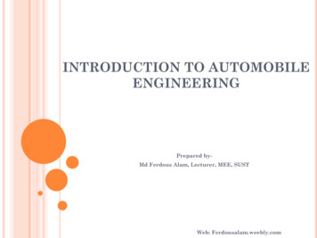
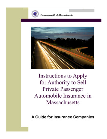
Chapter 1Chassis Frame And body1CHAPTER 1CHASSIS FRAME AND BODYIntroduction of Chassis Frame: Chassis is a French term and was initially usedto denote the frame parts or Basic Structure of the vehicle. It is the back boneof the vehicle. A vehicle with out body is called Chassis. The components ofthe vehicle like Power plant, Transmission System, Axles, Wheels and Tyres,Suspension, Controlling Systems like Braking, Steering etc., and also electricalsystem parts are mounted on the Chassis frame. It is the main mounting for allthe components including the body. So it is also called as Carrying Unit.Layout of Chassis and its main Components:The following main components of the Chassis are1. Frame: it is made up of long two members called side membersriveted together with the help of number of cross members.2. Engine or Power plant: It provides the source of power3. Clutch: It connects and disconnects the power from the engine flywheel to the transmission system.4. Gear Box
2Automobile Chassis And Body Engineering.docChapter 15. U Joint6. Propeller Shaft7. DifferentialFUNCTIONS OF THE CHASSIS FRAME:1. To carry load of the passengers or goods carried in the body.2. To support the load of the body, engine, gear box etc.,3. To withstand the forces caused due to the sudden braking oracceleration4. To withstand the stresses caused due to the bad road condition.5. To withstand centrifugal force while corneringTYPES OF CHASSIS FRAMES:There are three types of frames1. Conventional frame2. Integral frame3. Semi-integral frame1. Conventional frame: It has two long side members and 5 to 6 crossmembers joined together with the help of rivets and bolts. The frame sectionsare used generally.a. Channel Section - Good resistance to bendingb. Tabular Section - Good resistance to Torsionc. Box Section- Good resistance to both bending andTorsion2. Integral Frame: This frame is used now a days in most of the cars. There isno frame and all the assembly units are attached to the body. All thefunctions of the frame carried out by the body itself. Due to elimination oflong frame it is cheaper and due to less weight most economical also. Onlydisadvantage is repairing is difficult.3. Semi - Integral Frame: In some vehicles half frame is fixed in the front endon which engine gear box and front suspension is mounted. It has theadvantage when the vehicle is met with accident the front frame can betaken easily to replace the damaged chassis frame. This type of frame isused in FIAT cars and some of the European and American cars.VARIOUS LOADS ACTING ON THE FRAME:Various loads acting on the frame are1. Short duration Load - While crossing a broken patch.
Chapter 12.3.4.5.6.Chassis Frame And body3Momentary duration Load - While taking a curve.Impact Loads - Due to the collision of the vehicle.Inertia Load - While applying brakes.Static Loads - Loads due to chassis parts.Over Loads - Beyond Design capacity.STATE THE DIFFERENT BODIES USED IN AUTOMOBILES:The Automobile bodies are divided in two groupsBodyPassenger BodyCommercial body
4Automobile Chassis And Body Engineering.docAccording to Chassis design the body can divided into1. Conventional Type2. Integral Type3. Semi- Integral TypeAccording to other usage:1. Light vehicle Bodies - cars, jeeps2. Heavy vehicle Bodies – Busses, Lorries3. Medium vehicle Bodies - Vans, MetadoorsChapter 1
Chapter 1Chassis Frame And body5REQUIREMENTS OF BODIES FOR VARIOUS TYPES OF VECHILE:The body of the most vehicle should fulfill the following requirements:1. The body should be light.2. It should have minimum number of components.3. It should provide sufficient space for passengers and luggage.4. It should withstand vibrations while in motion.5. It should offer minimum resistance to air.6. It should be cheap and easy in manufacturing.7. It should be attractive in shape and colour.8. It should have uniformly distributed load.9. It should have long fatigue life10. It should provide good vision and ventilation.
6Automobile Chassis And Body Engineering.docChapter 1Short Answer Questions:1.2.3.4.5.List out the various components of chassis?What are the functions of Chassis frame?List out the types of Chassis frame?What are the frame sections used in Automobiles?What are the requirements of Bodies for various types of vehicles?Essay Type Questions:1. Draw the layout of conventional Chassis with a neat diagram andexplain about various parts on it?2. What are the different classification of bodies used in Automobilesand explain?
Chapter 2Steering System7CHAPTER 2STEERING SYSTEMIntroduction: This system provides the directional change in the movement ofan Automobile and maintain in a position as per the driver’s decision withoutmuch strain on him.REQUIREMENTS OF STEERING SYSTEM:a. It must keep the wheel at all times in to rolling motion with outrubbing on the road.b. This system should associate to control the speed.c. It must light and stable.d. It should also absorb the road shocks.e. It must easily be operated with less maintenance.f. It should have self-centering action to some extent.
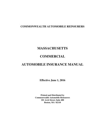
8Automobile Chassis And Body Engineering.docFunctions of Steering System:1.2.3.4.5.6.It helps in swinging the wheels to the left or right.It helps in turning the vehicle at the will of the driver.It provides directional stability.It is used to minimize the tyre wear and tear.It helps in achieving self-centering efforts.It absorbs major part of the road shocks.Main Components of Steering System:Chapter 2
Chapter 2Steering SystemThe following are the main components of steering system are1.2.3.4.5.6.7.8.9.Steering WheelSteering column or shaftSteering GearDrop Arm or Pitman ArmDrag LinkSteering ArmTrack-ArmsTrack Rod or Tie-RodAdjusting ScrewsTypes of Steering Gear Boxes:1.2.3.4.5.6.7.8.Worm and Wheel Steering Gear.Worm and Roller Steering Gear.Re-circulating Ball type Steering Gear.Rack and Pinion type Steering Gear.Cam and Roller Gear type Steering Gear.Cam and Peg Steering Gear.Cam and Double lever Steering Gear.Worm and Sector Type Steering Gear.Functions of Steering Gear Box:9
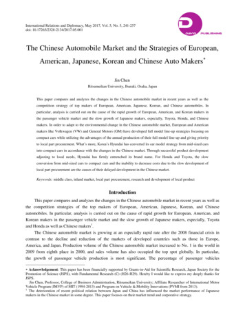
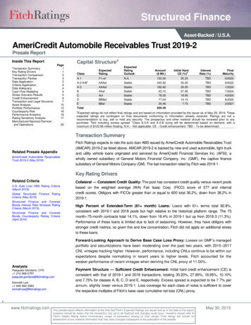
10Automobile Chassis And Body Engineering.docChapter 21. It converts the Rotary movement of the steering wheel in to theangular turning of the front wheels.2. It also multiplies drivers efforts and give MEHANICAL ADVANTAGE.1.Worm and Wheel Type: This type of steering gear has a square cut screwthreads at the end of the steering column; which forms a worm, at the end ofit a worm wheel is fitted and works rigidly with it. Generally covered shaft isused for the worm wheel. The worm wheel can be turned to a new positionthe drop arm can be readjusted to the correct working position.2. Re-circulating Ball Type: In this type of gear box the endless chain of ballsare provided between the worm and nut members. The nut form a ring ofrack having an axial movement. So that the sector on the rocker shaft racks,the balls roll continuously between the worm and nut. Being provided withreturn chambers at the ends of the worm. This method reduces frictionbetween worm and nut members. This type of steering gear is used for heavyvehicles.3. Rack and Pinion Type: This is common manual type of steering gear boxis used in most of the vehicles. In this type of steering a pinion is provided thebottom end of the steering column. The teeth of the pinion wheel in meshwith corresponding teeth provided on the rack, the end of which are
Chapter 2Steering System11connected to the stub axle through the rod. The rotating motion of thepinion operates the rack in FORE and AFT direction which in turn operates thestub axle.4. Cam and Lever Type: The cam and lever steering uses one or two leverstuds fitted in taper roller bearing. When the worm in the form of helicalgroove rotates the stub axle and it also rotates along with it. This imports aturning motion to the drop arm shaft.5. Worm and Sector Type: In this type the worm on the end of the steeringshaft meshes with a sector mounted on a sector shaft. When the worm isrotated by rotation of the steering wheel, the sector also turn rotating thesector shaft. Its motion is transmitted to the wheel through the linkage. Thesector shaft is attached to the drop arm or pitmen arm.Power Steering: Power steering reduces much strain on the part of the driverwhile negotiating sharp curves. It makes easy to turn sharp corners. It is usually
12Automobile Chassis And Body Engineering.docChapter 2arranged to be operative when the effort of steering wheel exceeds a predetermined value. It is fitted on heavy commercial vehicles and mediumcars.Steering Linkages: Steering Linkage is a connection of various links betweenthe steering gear box and the front wheels. The motion of the pitman armand steering gear box is transferred so the steering knuckles of the frontwheels through the steering linkages. The swinging movement of the pitmanarm from one side to the other side gives angular movement to the frontwheel through the steering linkages.Types of steering Linkages:1.2.3.4.5.Conventional steering Linkage.Direct cross type steering linkageThree piece steering linkagecenter arm steering linkageRelay type steering linkage.Slip Angle: The angle between direction of the motion of the vehicle and thecenter plane of the tyre is known as Slip Angle. It ranges from 8º to 10º.Under steer: When the front slip angle is greater than that of rear, the vehicletends to steer in the direction of side force. Then it is known as under steer. Thisprovides greater driving stability, especially when there is a side wind.Over Steer: When the rear slip angle is greater than that of front slip angle,the vehicle tends to mover away from the direction of center path. This isknown as over stear. This is advantageous when the vehicle moving on theroad having many bends curves.Steering Gear Ratio or Reduction Ratio: It has been defined as the “ numberof turns on the steering wheel required to produce on turn of steering gearcross shaft to which the pitman arm is attached. Generally it varies between14'.1 and 24'.1.Turning Radius: It is the radius of the circle on which the outside front wheelsmoves when the front wheels are turned to their extreme outer position. Thisradius is 5 to 7.5 m for buses and trucks.
Chapter 2Steering System13Wheel Alignment: It returns to the positioning of the front wheels and steeringmechanism that gives the vehicle directional stability, reduce the tyre wearto a minimum.Factors effects the wheel alignment:1. Factors pertaining to wheel:- a. Balance of wheels(Static and Dynamic)b. Inflation of tyre.c. Brake adjustments.2. Steering Linkages.3. Suspension System4. Steering Geometry –a. caster b. camber c. king pin inclination d. toe-inand toe-out etc.,Steering Geometry: It refers to the angular relationship between the frontwheels and parts attached to it and car frame.The steering Geometry includes1. Caster angle2. Camber angle3. King-pin inclination4. toe-in5. toe-out etc.,Caster Angle: This is the angle between backward or forward tilting of theking pin from the vertical axis at the top. This is about 2º to 4º. The backwardtilt is called as positive caster. The forward tilt is called negative caster.Camber: The angle between wheel axis to the vertical line at the top iscalled camber angle. It is approximately ½º to 2º.King-pin inclination: It is the angle between vertical line to the king pin axis.The inclination tends to keep wheels straight ahead and make the wheels toget return to the straight position after completion of a turn. The inclination isnormally kept 7º to 8º.
14Automobile Chassis And Body Engineering.docChapter 2Toe-in: It is the amount in minimum at the front part of the wheel pointsinwards approximately 3 to 5 mm. It prevents side slipping excessive tyrewear, proper rolling of front wheels and steering stability.Toe-out: It is the difference in angles between two front wheels and vehicleframe during turning. It is used to prevent dragging of tyre during turn.Reversible steering: When the deflection of road wheels is transmittedthrough the steering wheel to road surface, the system is called Reversible.If every imperfection of road surface causes the steering to rotate, itcauses much strain on the part of the driver to control the vehicle. It causesmuch strain on the part of the driver to control the vehicle. There fore such ofthe reversibility is not desired. But, some degree of reversibility desired, so thatthe wheel becomes straight after taking a curve.Irreversible steering: If the front road wheels does not transfer any deflectionto the steering which is called irreversible steering. After negotiating a curveand the steering wheel not returned easily, there causes the production of
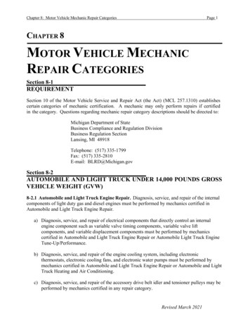
Chapter 2Steering System15un due stresses on the steering mechanism, therefore some degree ofirreversible also desired.Steering Mechanism: There are two types of steering gear mechanisms1. Davis Steering gear2. Ackermann Steering gear]1. Davis Steering Gear: The Davis Steering gear has sliding pair, it has morefriction than the turning pair, there fore the Davis Steering Gear wear outearlier and become inaccurate after certain time. This type is mathematicallyAccurate.The Davis gear mechanism consists of cross link KL sliding parallel toanother link AB and is connected to the stub axle of the two front wheel bylevers ACK and DBK pivoted at A and B respectively. The cross link KL slides inthe bearing and cross pins at its ends K and L. The slide blocks are pivoted onthese pins and move with the turning of bell crank levers as the steeringwheel is operated. When the vehicle is running straight the gear is said to bein its mid-position. The short arms AK and BL are inclined an angle 90 t α totheir stub axles AC and BD respectively. The correct steering depends uponthe suitable selection of cross arm angle α, and is given byTan α b/2lWhere b AB distance between the pivots of front axle.l wheel base2.Ackermann Steering System: It has only turning pair. It is notmathematically accurate except in three positions. The track arms are madeinclined so that if the axles are extended they will meet on the longitudinalaxis of the car near rear axle. This system is called ackermann steering.STEERING DEFECTS AND THEIR CAUSES AND REMEDIES:1. Wheel wobble: The oscillation of the front wheels at low speeds iscalled wheel wobble.Causesa. In Correct Dynamic Balancingof wheels.b. Uneven Tyre pressureRemediesa. Correct the wheel balanceb. Check the tyre pressurec. The camber may be incorrect or c. Adjust suitably.unevend. The ball joints may be worn out. d. Replace with a new one
16Automobile Chassis And Body Engineering.doce. Excessive castere.f. Steering gear or wheel bearingmay be loosen.g. Tyre may worn unevenlyf. Adjust or ReplaceChapter 2Adjustg. Replace2. High Speed shimmy: The oscillation of the front wheels at high speed iscalled high speed shimmy.a.b.c.d.Wheel Rim may be buckled- Straighten or replaceFront wheel bearing may loose or worn out - Tighten or ReplaceFaulty shock Absorber- ReplaceIncorrect toe-in- Adjust3. Excessive backlash in steering:a. Steering gear base may be loose-Tightenb. Drop arm may be loose on splines- Replacec. Front wheel stub axle bearing loose or worn out-Tighten or Replaced. Loose steering Linkages- Tighten Properly4. Steering Wander: The moving of Vehicle slightly in one side is known aswanderinga. Tyre pressure in two sides is not equalb. Steering knuckle bearing tightc. Badly worn Tyred. Incorrect Toe-in- Check and correct-Adjust- Replace- Correct it.5. Hard Steering: When the effort required for steering is more it is calledhard steering.a. Low Tyre pressureb. Excessive casterc. Steering gear too tightd. Incorrect wheel Alignment- Correct pressure- Adjust- Adjust- Adjust
Chapter 2Steering System17COMPARATIVE STEERING DATA OF SOME INDIAN AUTOMOBILESVehicle make TypeofSteeringHindustanRackAmbassador &Mark IIPinionCamberCastor½”8 1/4”2Fiat 1100Worm&Roller(0 to 30)degrees /- 20’3Jeep ation3”ToeSteeriin(mm ng)Ratio2414:1(27degre degreeses 10mts /- 10mts 30secs1 to 9unladen7laden164:171/2degrees1.2 to2.414:1,12:1
18Automobile Chassis And Body Engineering.docChapter 2Short Answer Questions:1.2.3.4.5.6.7.What are the Requirements of Steering systems?Explain the functions of steering systems?List out the main components of steering system?What are the functions of steering Linkages used the Automobiles?What are the types of steering linkages used the Automobiles?What is meant by wheel wobbling?What are the causes for high Speed Shimmy?Long Answer Questions:1. What are the types of steering gear boxes used and explain any oneof them?2. What is meant by Steering Geometry and explain with neat sketches?3. Explain about different Steering mechanisms i.e. Dan’s and Ackermansteering with neat diagrams?4. Explain the following in brief:a. Slip Angleb. Under Steer and Over Steerc. Reversible Steering and Irreversible steeringd. Turning Radius
Chapter 3BRAKING SYSTEM19CHAPTER –IIIBRAKING SYSTEM:INTRODUCTION:Braking is the mechanism in the motor vehicle which is usedto slowing down and stopping the vehicle to rest in the shortest possibledistance.Principle of Braking system: While operating the braking system the KINETICENERGY of moving vehicle is converted in to HEAT ENERGY.Functions of Brakes: Brakes have the following functions.1.It is used to stop the vehicle.2.It is used to control the speed where and when required.3.It is used to control the vehicle while descending along the slope.4.To park the vehicle and held it in stationary position without the presence ofDriver.Requirements of Automobile Brakes:1.It should work efficiently irrespective of road condition and quality.2.The retardation must be uniform throughout its application.3.The pedal effort must be within the convenient capacity of the driver.4.It must be reliable and should not be effected by heat water and dust.5.It should be in minimum weight.6.It should have long life.7.It should be easy to maintain and adjust.8.Noise and vibrations are to be minimum.9.There should be provision for secondary brake or parking brake.Stopping distance and Braking efficiency:For practical measure for braking efficiency that of the minimumdistance in which it can be brought in to rest after the brake is applied.The stopping distance depends upon1.Grip between the tyre and road surface.2.Tyre tread condition.3.Tyre inflation.4.Nature of road surface.The stopping distance is calculated byD kv2Where d stopping distance in kilometers.K Constant depending upon the road and tyre inflation.V velocity of the vehicle per hour.
20Automobile Chassis And Body Engineering.docChapter 3The value of k is 1/25 for 4 wheel braking system.1/12 for 2 wheel braking system.The braking efficiency is calculated by the equation:η V2/3D where v velocity of the vehicled stopping distance.Condition of BrakeBraking efficiency in %1.Perfect2.Excellent3.Good4.Fair5.Poor6.Bad7.Very bad90%77%70%60%50%37%30%Below Fair is very danger.Classification of Brakes: The following are the classifications of Brakes:1.By method of powera) Mechanical brakesb) Hydraulic brakesc) Vacuum brakesd) Air brakese) Electrical brakesf) Magnetic brakesg) Air assisted hydraulic brakes2.By method of application:a) Service or foot brakesb)Parking or hand brakes3.By method of operation:a) Manualb) Servoc) Power operation4. By method of Braking contacta. Internal Expanding Brakes
Chapter 3BRAKING SYSTEM21b. External Contracting Brakes.5. By Method of Applying Brake force:a. Single Acting Brakes.b. Double Acting Brakes.Types of Mechanical Brakes:a. Drum Brakes (Internal Expanding or External Contracting)b. Disc Brakes (Single or Two caliper)Drum Brakes:Construction: The main components of drum brakes are1. Brake drum2. Back plate3. Brake shoes4. Brake Liners5. Retaining Springs6. Cam7. Brake LinkagesIn this system the wheel is attached to drum. There are brake shoes used tocontact the rotating drum for braking operation. The shoes provide lining ontheir outer surface. The cam is used to lift the brake shoes at one end, otherend is connected by some method so as to make as the brake sleeve comeinto contact in the brake drum. The retaining spring is provided for bringingthe brake shoes back to its original position, after releasing the brake pedal.All these parts are fitted in the back plate and enclosed with brake drum. Thissystem .Working: When the pedal is pressed the cam moves the shoes outwardsthrough linkages, there by coming in frictional contact with the rotating drum.As soon as the brake pedal is released the retaining springs help the brakeshoes to brought back and release the brakes.2. Disc brakes: There are two types of disc brakes:1. Spot Typea. Swinging Caliper Typeb. Sliding caliper type2. Clutch TypeConstruction: The discs are made of gray cast Iron. The brake pressure incase of disc brakes have to be much lighter than the drum brakes.
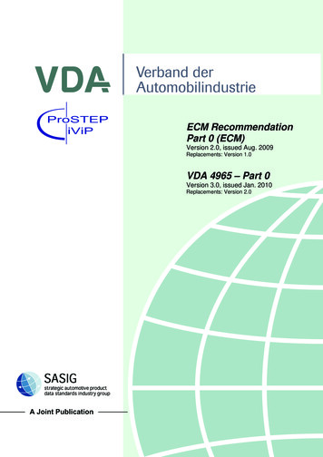
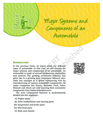
22Automobile Chassis And Body Engineering.docChapter 3It consists of rotating disc and two friction pads which are actuated bythe four hydraulic wheel pistons contain in two halves of an assembly is calleda caliper. The caliper assembly is secured to the steering knuckle in a frontwheel brakes. The road wheel is fashioned to the outer surface of the disc.The friction pads rides freely on each side of the discs. They are in positionbeing the hydraulic systems.Working:When the brakes is applied hydraulic pressure is supply to the fluid inlettube, due to which the wheel cylinder piston force the friction pads againstthe rotating disc. In the released piston, the spring hold the piston pads sothat they maintain contact with disc surface.Construction and Working of Hydraulic systems:Hydraulic brakes make used of hydraulic pressure to force brake shoesout words against the brake drum based on PASCAL’S LAW.Construction: The main components of the system is1. Master Cylinder2. Wheel CylinderThe figure shows the master cylinder is connected by tubing to thewheel cylinder, at each of the four wheels. The system is filled with the liquidunder light pressure when the brake is not in operation. The brake fluidgenerally a mixture of glycerin and alcohol or caster oil, denatured alcoholand some additives.The brakes shoes which are mounted on the inner side of the brakedrum and do not rotate. The brake liners are fitted on the outer surface of the
Chapter 3BRAKING SYSTEM23brake shoes. The brake pedal is connected to the master cylinder piston bymeans of a piston rod.Working: When the brake pedal is pressed the piston is forced in to themaster cylinder, the hydraulic pressure is applied equally to all wheelcylinders. The pistons in the wheel cylinders pushed outwards against thebrake drum.When the driver release the brake pedal, the piston in the mastercylinder returns back to its original position due to the return spring pressure.Thus the pistons in the wheel cylinder come back in its original inward position.Thus the brakes are releasedConstruction and working of Master CylinderMaster Cylinder: The Master Cylinder is the heart of the hydraulic brakesystem. It consists of two main chambers. The fluid reservoir which containsthe fluid to supply to the brake system, and the compression chamber inwhich the piston operates. The reservoir supplies fluid to the brake systemthrough two ports. The larger port is called the filler or intake part and isconnected to the hollow portion of the piston between the primary andsecondary cups which act as piston seals. The smaller port is called the relief,bypass or compensating port which connects the reservoir directly with thecylinder and lines when the piston is in the released position.When the brake pedal is depressed, the master cylinder piston movesforward to force the liquid under pressure into the system. The relief port issealed out of the system. The liquid pressure is conducted to the wheelcylinders, where it forces the wheel cylinder pistons out wards. These pistonsforce the brake shoes out against the brake drums.
24Automobile Chassis And Body Engineering.docChapter 3When brake pedal is released, the return spring quickly forces themaster cylinder piston back against the piston stop. Because the fluid in thelines returns rather slowly, a vacuum tends to form in the cylinder in front ofthe piston. This causes the primary cup to collapse to allow the liquid to flowfrom the reservoir through the filter port past the piston to fill the vacuum.Construction and working of Wheel CylinderWHEEL CYLINDER: Wheel cylinder is the second important hydraulic brakesystem. It consists of two pistons which can move in opposite directions by thefluid pressure. It is rigidly mounted on the brake shield or backing plate. Theboots protect the cylinders from foreign substances. Bleeder valves areprovided in the cylinder to permit air and liquid to be pumped out of thesystem during of the bleeding operation .Piston cup fits tightly in the cylinder against each piston and seal themechanism against leakage of the brake fluid. A Spring serves to hold thecups against the piston when the pressure is decreased.When the brakes are applied the brake fluid enters the cylinder from abrake line connection inlet between the two pistons. It causes to force outthe two pistons in opposite directions. This motion is transmitted to the brakeshoe. Directly or through links force them against the brake drum, thusapplying the brake.Construction and working of Tandem master CylinderIn this master cylinder there are two pistons in the and hydraulicpressure developed in two chambers one for the front left, and rear rightbrakes and other for the front right and rear left brakes.In tandem master cylinder one cylinder operates the front brakes whilethe other cylinder operates the rear brakes.
Chapter 3BRAKING SYSTEM25Construction and working of Air Brake System:The air brake system consists of two-stage air-compressor driven by thecrankshaft or gearbox shaft. It takes air from atmosphere, compresses it anddelivers to the air reservoir through un-loader valve. Where the pressure ofthe reservoir reaches the maximum degree, the un- loader valve opens to theatmosphere. Then the compressed air is directed in to the atmospheredirectly.Each of the four wheels fitted with brake chambers consists of adiaphragm, and which the air pressure is applied and pushes it. This forceoperates the cam actuating lever and applies the brake. Each of the brakechamber is connected to the brake pedal, and air filter is also fitted betweenthe brake valve and reservoir.Working: When the brake pedal is pushed the brake valve opens andcompressed air is allowed in to the brake chamber. The brake valve consistsof three passages.1. Air intake 2. Exhaust 3. Brake chamberWhen the brake pedal is pressed the exhaust passage will be closedand Air intake passage open and compressed air goes back to the chamber.During return stroke the exhaust passage opens while intake closes a
A Text Book on Automobile Chassis and Body Engineering (A text book for 2 Vocational and Diploma Students of Mechanical Engineering) Author Sri. N.R.HEMA KUMAR Lecturer in Vocational, Department of Vocational Education, Government Junior College, PALAMANER. Editor Sri. P.L.N. P