Transcription
Guide A:Environmental DesignWIFI: Password: MOL15XMOL15XFollow @CIBSE
Guide A: Environmental DesignLaunch: 22 July 201518:00 – Session 1 Derrick Braham, Chair - Welcome Chapter 0 - Quality in Environmental Design Chapter 1 Environmental Criteria for Design Chapter 2 External Design Data18:45 – Session 2 Chapter 3 Thermal properties of Building Structures Chapter 4 Ventilation and Infiltration Chapter 5 Thermal Response and Plant Sizing19:25 – Session 3 Chapter 6 Internal Heat Gains Chapter 7 Moisture transfer and Condensation Chapter 8 Health Issues 20:05 - Concluding Address 20:10 – Drinks receptionWIFI:Password: Follow @CIBSE
Derrick BrahamGuide A Steering Group ChairWelcome to the Launchwww.cibse.org
Guide A: Environmental DesignThis is the 8th edition of CIBSE Guide A: Environmental Design.It is the premier UK technical reference source for designers and installers ofheating, ventilating and air conditionings services.It enables engineers to design comfortable, environmentally sustainable, energyefficient buildings that are a pleasure to live and work and spend leisure time in.It comprehensively updates its immediate predecessor and contains many significantchanges in both format and content. Published March 2015 – Most popular CIBSE documentDownloaded 6,677 times (free to members)Hard copies sold 58.www.cibse.org
Guide A: Environmental DesignIt presents the professional expertise of UK’s foremost designers and researchers inthe HEVAC field.Many represent CIBSE on International, European and National standardscommittees.All are volunteers and most have served on the earlier Guides, CIBSE is especiallygrateful to their employers who have generously given the time off for this work.www.cibse.org
Guide A: Environmental DesignEach Guide A is part of a continuing publication programme and each successiveedition relies on material provided for previous editions.All this earlier material has been comprehensively reviewed , revised and broughtup to-date and many chapters have had to be increased in content . Indeed onenew chapter had to be created to reflect the changes in quality standards /performance / reliability now expected, since the previous edition.www.cibse.org
Guide A Steering Committee Brian Anderson – BRE Scotland David Arnold – Troup Bywaters AndersMarialena Nikolopoulou – Universityof Kent Foroutan Parand- AECOM Michael Holmes – Arup Michael Humphreys – Oxford BrookesChris Sanders – Glasgow CaledoniaUniversity Geoff Levermore – University ofManchester David Williams – WSP/ParsonsBickerhoff Martin Liddament – VEETEC Ltd Runming Yao – University of Reading Fergus Nicol – Oxford Brookes Sanaz Agha – CIBSE (secretary)www.cibse.org
Foroutan ParandAECOMChapter 0 - Environmental Designwww.cibse.org
CIBSE Guide A: Environmental designCIBSE Guide A:Environmental design is the premier referencesource for designers of low energy sustainablebuildings.It is perceived as a guide to good current practiceand CIBSE members are encouraged to follow theguidance in discharging their design duties.www.cibse.org
Chapter 0 - Environmental DesignPurpose of Chapter 0:1-Introduction to the guide.emphasise on sustainability2-Emphasise on the need for quality of designIs the product (building) fit for its purpose? Safety, health & comfort Low impact on environmentwww.cibse.org
Achieving quality Holistic approach to design Early engagement in the design process Environmental design process Quality Plan Quality ProceduresA0’s objective: quality sustainable designwww.cibse.org
Holistic approach to design Understanding the brief Understanding theconstraints Communication with otherdesign team members Integrated designOutput: Healthy, safe,comfortable, sustainableFigure 0.1 of the guidewww.cibse.org
Early engagement & options test Highlights importance of lowenergy design options Design is a sequential butiterative process When information is notavailable, assumptions must bemade with the risk associated tothem.www.cibse.orgFigure 0.2 of the guide
Design flow chart and how to use the guide A generic design flow chartfor building services design: Also a guide to differentchapters of the Guide AYou may need to adapt the flowchart to your practice andprocesseswww.cibse.org
Design is not just compliance with Part L Health and comfort in some designs may havesuffered as a side effect. The guide warns that design is not just Part L. Part L uses a single usage scenario. Designers must consider all 018:0035000:00Date: Wed 01/Augwww.cibse.orgDry resultant temperature: Bedroom GF18 (block 16 -windows30pc.aps)Room CO2 concentration: Bedroom GF18 (block 16 -windows30pc.aps)Internal gain: Bedroom GF18 (block 16 -windows30pc.aps)Solar gain: Bedroom GF18 (block 16 -windows30pc.aps)MacroFlo external vent: Bedroom GF18 (block 16 -windows30pc.aps)Dry-bulb temperature: (block 16 -windows30pc.aps)200Volume flow (l/s)206500.35CO2 concentration (ppm)QA plan should help avoid the potentialproblem.35Gain (kW)Part L has focused minds of clients anddesigners on energy aspects of the design.Temperature ( C)
Quality plan Quality Policy Right Resources Management commitmentKnowledge, skill, toolsQuality Procedures How to do assessments How to check the calcualtions How to do house keepingAdapt to your practice and problemsFor more details and how to set up QA refersto CIBSE AM 11A complete rewrite of AM11 will bepublished soonwww.cibse.orgFigure 0.5 – Quality flow chart
Fergus NicolOxford Brooks UniversityChapter 1 - EnvironmentalCriteria for Designwww.cibse.org
Purpose of Chapter 1This chapter is intended to delineate the environments that buildingoccupants will find comfortable.The interaction between people and buildings takes place in a number ofways, and many aspects of the environment are important: the thermal environment (both inside the building and outside) the lighting the ventilation any noise or vibration.The chapter brings together information in all these aspects and triesto give the best and most up-to-date information on which buildingservices engineers can base their designs.www.cibse.org
Thermal environment and comfortLargely rewritten in the main with sections on Comfort Thermal environment, defining variables and looking at the 6 basicvariables Models of thermal comfort – adaptive and PMV. How they are derived,how they differ and what they have in common Environmental criteria for indoor spaces.www.cibse.org
Thermal environment and comfortOverheating: reflecting the criteria for overheating introduced in TM52Additional factors affecting comfort including personal factors such as age,gender, state of health as well as environmental factors such asasymmetry, floor temperatures, draughts and turbulence and the influence ofother dimensions such as lighting on thermal comfort.Each section reviews the available evidence and its reliabilitywww.cibse.org
Outdoor thermal comfortAn entirely new section which addresses the importance of the outdoor environmentand how it can be optimisedRequirements for outdoor airLooks at the need for fresh air and how it can be affected by therate of supply and the need to control pollutants. Indoor AirQuality is addressed in chapter 8www.cibse.org
Noise and VibrationTwo sections have been thoroughly rewritten Noise deals with the measurement and effect of noise viewing soundboth as a means of communication and as a source of discomfort. Thesection give plentiful references to guidelines and standards Vibration is dealt with from the point of view of the danger is poses tobuildings and their occupants dealing with sources as well asconsequenceswww.cibse.org
Visual environmentLighting for Safety and visual performanceThe criteria for daylighting and the role of energy efficiency in lightingThis section has been shortened and readers are referred to the publications of theSLLReferencesThere is a copious list of references which can be used forfurther readingwww.cibse.org
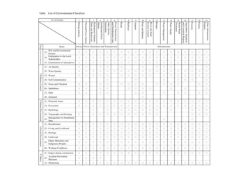
Table 1.5 (pages 1-10 to 1-13) drawstogether the recommended values fortemperatures, air supply and filtration,illuminance and noise levels for differentbuilding types and spaceswww.cibse.org
ContributorsThermal environment and thermal comfort (Michael Humphreys andF.N.)Outdoor thermal comfort (M.N.)Air supply (Martin Liddament)Visual environment (David Loe, Mike Wilson and Peter Tragenza)Noise and Vibration (Bob Peters and John Shelton)www.cibse.org
Geoff LevermoreUniversity of ManchesterChapter 2 - External Design Datawww.cibse.org
Updates and new data in A2External design dataProbabilistic climate profiles (ProCliP) graphs give an appreciation of thetemperature rises through the century for different emissions scenarios.The urban heat island (UHI) data has been updated to give the UHI effect forthe City of London and various distances out from it compared to Heathrow.Manchester data is also provided.www.cibse.org
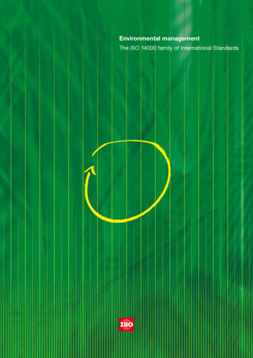
14 stations, full data including Londonwww.cibse.orgAldergroveElmdon ColeshillRhoose, St AthanTurnhouse ,GogarbankAbbotsinch, BishoptonChurch FentonHeathrowManchester Ringway,Newcastle Newcastle fordAlbermarleMarhamWatnallMountbattenHurnBrize Norton
Details of the climate of the 14 stations meanannual and summer tempswww.cibse.org
Updated cold and warm weather data as well aswet & dry bulb tempswww.cibse.org
Updated solar for 14 sites with simpler solair tempITHd global hor irradwww.cibse.org
Updated wind(1 knot 0.51 ms-1)www.cibse.org
Climate change data and chartswww.cibse.org
Urban heat island intensity (UHII)UHII is the extra temperature rise in the urban area compared to the rural area.For the CIBSE data the UHII is relative to Heathrow and near Manchester airports.Add on the UHII factors (from CIBSE tables) to the so-air temperatures.Londonwww.cibse.orgManchester
Brian AndersonBRE ScotlandChapter 3 –Thermal properties ofBuilding Structureswww.cibse.org
Thermal properties of building structures Chapter 3 covers the determination of heat transmission properties ofbuilding elements – walls, floors, roofs, windows. It provides methods of calculation and associated data on the thermalconductivity of materials.www.cibse.org
Multifoil insulation Products that consist of several layers of foil separated by othermaterials New British Standard (BS EN 16012) which defines how tomeasure and declare insulation propertieswww.cibse.org
U-values of elements with inhomogeneous layersBridged elements are assessed usingthe mid-way point of the upper andlower limits of thermal resistance.Now a maximum of 1.5 for the ratioof the two limits for the result ro beconsidered valid.www.cibse.org
Blinds, curtains and secondary glazingRevised data:www.cibse.org
Windows and roof windowsRevised data, including: Gas filling between panes Low emissivity of glass surfaces Different frame types Effect roof pitch for roof windowswww.cibse.org
Thermal by-passes Can be a significant cause of heatloss Provides data for unfilled cavityparty walls connected to cold loftspace (assigning a U-value to theparty wall) Future research may provide moredetailed informationwww.cibse.org
Thermal bridging Of potentially increasing significance as insulation of structures is raised Heat loss calculations should include the effect of thermal bridges andthe Guide indicates how they can be evaluatedwww.cibse.org
Martin LiddamentVEETEC LtdChapter 4 – Ventilation andInfiltrationwww.cibse.org
Chapter 4 Ventilation and Air InfiltrationAt the time of preparation issues about the future of ventilation methodsand the impact of infiltration on energy consumption were important.Considerations included:Airtightness – Legal requirements to reduce CO2 emissionsVentilation more mechanised to provide controlThe Future of Natural Ventilationwww.cibse.org
Background: The Future of Natural VentilationBuilding Regulations(June 2009 Consultation Volume 1)“It is likely to become morechallenging to provide adequateventilation rates using naturalventilation systems and this willgive impetus to mechanicalventilation systems”.www.cibse.orgNHBC (2012)“In order to satisfy the energy use demands ofthe Code for Sustainable Homes in homes builtto Code Level 4 and above, it is expected thatmechanical ventilation with heat recovery willneed to be applied in order to achieve anacceptable indoor climate, which representssomething of a culture change in the UK.
However Many UK Organisations promote natural ventilationSaving Carbon –Improving HealthThe Carbon Trust: “A typical airconditioned building has double theenergy cost and associated CO2emissions of a naturally ventilatedbuilding. It is also more likely to haveincreased capital and maintenancecosts”.The Commission for Architectureand the Built Environment(responsible for UK secondaryschool design): “Many basicissues of energy performancehave been overlooked includingthe potential to minimisemechanical ventilation by usingpassive ventilation”.www.cibse.org“Buildings designed with passiveventilation haveimproved resilience to energysupply failure and aremore energy efficient thanmechanically ventilatedbuildings. In an acute hospital up to70% of net floor space could beentirely or partially naturallyventilated”.
Background: OutcomeStill a strong demand for buildings to benaturally ventilatedMuch progress on the implementation ofmechanical systems in buildings that wereformerly naturally ventilated (e.g. dwellings)Many lessons still to be learnt about ventilationperformance in practice and about the impact ofairtightnessA continuing need to consider all aspects ofair infiltration and ventilation in Guide Awww.cibse.org
Proposed Structure and ContentMaintain as much of theexisting information aspossibleExtend information onmechanical systemsUpdate information on airtightness (air permeability)and testing.Cover ventilation related air quality issueswww.cibse.org
What is in the Chapter 4 of the CIBSE Guide?- An attempt to give a basic understanding with simple toolsthat can be set up on a spread sheet.- Includes:-www.cibse.orgBasic theoretical concepts WITH limitationsAirtightness (air permeability testing)Mechanical ventilationHeat recoveryNatural ventilation and infiltration includingwind, stack and combined wind and stackdriving forcesSingle sided ventilationTerrain conditionsShelteringVariability and control of ventilation systemsBasic calculationsDilution equationRelevant Data
Mechanical Systems-System TypeDisplacement VentilationMixing VentilationHeat RecoveryFiltrationHeating/CoolingSpecific Fan PowerBased on BRECSUGood Practice Guide 257www.cibse.org
Natural Ventilation Systems-System TypeWeather ParametersVariability of Driving ForcesCalculation MethodsBased on BRECSUGood Practice Guide 257www.cibse.org
Calculating Ventilation RateHourly Weather DataBuilding nsAirtightnessOpeningDimensionsTerrain &ShieldingCalculation Modelfor- Air Infiltration- Ventilation Rate- Air Quality- Energy DemandMech VentRatesRoomTemperaturewww.cibse.orgAir ilation RateIndoor Pollutant ConcentrationIndoorEmissions
Variability of NaturalDriving ForcesHourly Temperature Birmingham 1997ExampleHourly Temperature (Birmingham)35308760 hours of data in a yearTemperatureIdeally needto carry out anhourly analysis. Only possiblewith simple calculationtechniques25Temperature (Deg C)20151050-5-10Hourly Wind Speed Birmingham 19970Example Hourly Wind Speed (Birmingham) VEETECH Ltd.14Wind Speed (m/s)12Wind8WW64200730146021902920365043805110Time (Hours) Jan - urs161073080308760511058406570730080308760 VEETECH Ltd.
Can use hourly wind and temperature weatherdata from Chapter 2www.cibse.org
Indoor Air tion Equation - Pollutant Removalwww.cibse.orgAgriculturalChemicalsPollen
Ventilation Control using Metabolic CO2:www.cibse.org
Other Items Related to VentilationEmpirical infiltration data for various air permeabilitiesand building sizeswww.cibse.org
Other Items Related to VentilationTables of (approximate) wind pressure datawww.cibse.org
Other Items Related to VentilationTables of (approximate) component leakage datawww.cibse.org
Other Items Related to VentilationSimple Algorithm that solves the Ventilation/Infiltration Equationfor natural and mechanical driving forces (single zone)sizes.www.cibse.org
Michael HolmesArupChapter 5 – Thermal Responseand Plant Sizingwww.cibse.org
David WilliamsWSP/Parsons BickerhoffChapter 5 – Thermal Responseand Plant Sizingwww.cibse.org
Chapter 5, Thermal Design Plant Sizing andEnergy ConservationIntroduction Current form based on 1999 revision – recognition of design calculation at variouslevels Next revision in 2006 – ‘computerisation’ of the Guide 2015 revision -www.cibse.orgDevelopment along similar veinFurther coverage on airflow modelling, system simulationand energy calculationTitle change from ‘Thermal Design and Plant Sizing’ to‘Thermal Design Plant sizing and Energy Conservation’
Chapter 5, Thermal Design Plant Sizing andEnergy Conservation Michael Holmes (Arup)Principle author Matthew Collin (MC Building Physics)Examples and the Performance assessment methodology later moved to A0 Malcolm Cook (Loughborough University) and Darren Woolf (Loughborough University and Hoare Lea)Airflow modelling Yudish Dabee (Mott MacDonald)Methodology for the calculation of cooling loads Foroutan Parand (AECOM)Quality management which evolved into A0 Andrew Wright (De Montfort University)Thermal mass also editing early versions David Williams (WSP Parsons Brinckerhoff)Energy consumption and technical checkwww.cibse.org
Chapter 5, Thermal Design Plant Sizing andEnergy ConservationChapter 5 – Examples of New MaterialAir flow modellingComponent plant modellingHVAC SystemModelling –PsychrometricModellingNodal networksComputationalFluid Dynamicswww.cibse.orgDetailedComponentModelling
Chapter 5, Thermal Design Plant Sizing andEnergy ConservationChapter 5 – Examples of New MaterialOverheating Risk CalculationThermal Storage SystemsPhase und thermalstoragewww.cibse.org
Chapter 5, Thermal Design Plant Sizing andEnergy ConservationChapter 5 – Examples of New MaterialBuilding Energy DemandRole and limitations of energy modelsApplication of calculation methods:- Annual benchmarking- Bin methods and degree days- Quasi-steady state- Hourly dynamic calculations- Geometry, zoning, climate,materials, solar, ventilation,heat gains, non-thermal,plantwww.cibse.orgBuilding heatflow paths
Chapter 5, Thermal Design Plant Sizing andEnergy ConservationChapter 5 – Sister PublicationApplication Manual 11 – Building Performance Modelling (AM11)Due for publication in the next few monthsRefresh of the 1998 manual Quality AssuranceModelling for Building Energy RegulationEnergy ModellingThermal Environment ModellingVentilation ModellingLighting ModellingPlant and Renewable Energy SystemsCase Studieswww.cibse.org
David ArnoldTroup Bywaters AndersChapter 6 – Internal Heat Gainswww.cibse.org
Environmental Design 2015 Guide AChapter 6 Internal Heat Gains6 Internal heat gains6.1 Introduction6.2 Benchmark values for internal heat gains6.3 Occupants6.4 Lighting6.5 Personal computers and office equipment6.6 Electric motors6.7 Cooking appliances6.8 Hospital and laboratory equipment6.9 Heat gain from laboratory animals6.10 Domestic appliances and equipmentReferences 6-11Appendix 6.A1: Rate of heat gain from restaurant/cooking equipment 6-13www.cibse.org
Environmental Design 2015 Guide AChapter 6 Internal Heat Gains Provides information on heat gains in buildings and guidance fordesigners to assist them estimating the most appropriate allowances Designers can either calculate internal heat gains from basic principles orbase them on ‘Benchmark’ values Benchmarks are available for typical buildings and listed in table 6.2www.cibse.org
Environmental Design 2015 Guide AChapter 6 Internal Heat GainsBCO Guide 2014 Terminal Cooling Small Power AllowanceConventional Office Density 1:10m220 W/m2High Density Offices 1:8m225 W/m2www.cibse.org
Environmental Design 2015 Guide AChapter 6 Internal Heat GainsWhat’s new?a) Table showing the estimated heat emission from an adult male body at differenttemperatures and levels of activity omitted from 2006 edition re-introduced inresponse to requests;b) Heat emitted by office equipment updated to reflect current trends in moreefficient models now in use;c) Heat emitted by low energy lamps added;d) New measurements of the radiative, convective and conductive split of heat fromlighting fittings added;e) New heat emission from cooking equipment added;f) Tables of heat emitted by Hospital and Medical equipment added.www.cibse.org
Environmental Design 2015 Guide AChapter 6 Internal Heat Gainswww.cibse.org
Environmental Design 2015 Guide AChapter 6 Internal Heat GainsHeat emitted by office equipment updated to reflect current trends in more efficientmodels now in use;The results of new experimental measurements of heat gain from office equipmentincluding from flat panel monitors. The data is now presented with the radiantconvective split. have been carried out by Hosni and Beck (2011). The results areshown in Table 6.6.www.cibse.org
Environmental Design 2015 Guide AChapter 6 Internal Heat GainsHeat emitted by low energy lamps added;The Society of Light and Lighting does not recommend the use of LED substitutefluorescent lamps but, at the time of writing, several new fittings that are more energyefficient and offer reasonable quality of light have become available commercially.www.cibse.org
Environmental Design 2015 Guide AChapter 6 Internal Heat Gainswww.cibse.org
Environmental Design 2015 Guide AChapter 6 Internal Heat Gains20 Fenchurch Streetwww.cibse.org
Chris SandersGlasgow Caledonia UniversityChapter 7 – Moisture transfer andCondensationwww.cibse.org
Major changesMore emphasis on importance of air movement as a mechanism for moisturetransportLiquid water storage and movement within porous materials forms an essential partof advanced prediction models to BS EN 15026IntroductionNew paragraphs emphasising the importance of air leakage into structures as amechanism for moisture transport into fabric, and therefore the need to limit airleakage.www.cibse.org
7.3 Psychrometry of water vapour in airExpanded version of previous 7.6.1, with simple psychrometric chart to explainderivation of parameters.www.cibse.org
7.4 Moisture content of materialsEquation for sorption isotherm, relating moisture content of material to the ambientRH introduced. Parameters of the equation introduced to expanded Table 7.1www.cibse.org
7.5 Mechanisms of moisture movementNew section 7.5.3 discussing role of surface buffering in controlling internal humidity.New section 7.5.5 discussing liquid water movement through pores, which is thedominant mechanism in the more advanced models under BS EN 15026.Section 7.5.6 on air movement expanded.www.cibse.org
7.7 Interstitial CondensationExpanded from the old 7.6.5, with new sections 7.7.1 Risks of interstitial Condensation, 7.7.2 Diffusion (Glaser) model, 7.7.3 Drying of components with entrapped moisture 7.7.4 Full models, which discusses the models standardised in BS EN 15026, i.e.WUFI.www.cibse.org
7.8 Inside and outside design conditionsGenerally unchanged from the old 7.7, but with the addition of climate classesdefined in BS EN ISO 13788 and BS EN 15026.New sections 7.8.5.2 and 7.8.5.3 on boundary conditions for ground floors.www.cibse.org
7.9 Condensation calculationsGenerally unchanged from old 7.8, with addition of new section 7.9.2.5 Condensationin the insulation of cold pipes, where calculations use cylindrical coordinateswww.cibse.org
Current DevelopmentsDCLG have just let an 18 month contract to PRP Environmental for a completereview of knowledge and research in this area; once that is complete towards theend of 2016 they will start the process of revising Approved Document CHistoric Scotland Technical Paper 15, by Joseph Little, which should be publishedshortly, is a major analysis of the processes concerned with moisture risks ininsulated solid masonry wallswww.cibse.org
Current DevelopmentsAnalysis based on BS EN 15026 (i.e WUFI) is being increasingly used, in place ofthe traditional ‘Glaser’ method in BS EN ISO 13788, without there being clearguidance as to which method is appropriate for any given system.It is apparent that the distinction that has been made between problems of ‘interstitialcondensation’ and problems from other moisture sources, especially driving rain, isunhelpfulBS 5250, will be completely revised in 2017www.cibse.org
Marialena NikolopolouProfessor of Sustainable Architecture, Director of CASEKent School of ArchitectureChapter 8 – Health Issueswww.cibse.org
Thermal discomfort and health implications Regulatory backgroundHeat stress/discomfort and heat exhaustionAcclimatization and difference between heat and coldCold discomfortImplications on the human body and productivity Thermal environment and adaptive comfort Links with A1 Burnswww.cibse.org
Humidity Thermal comfort Problems with high humidity: of increasing concern in the UK From 4 paragraphs to 1.5 page House Dust Mites Recommendations Problems with low humiditywww.cibse.org
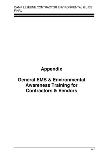
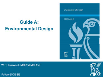
House dust mitesThe mite population index model: graphicrepresentation of lab results for populationgrowth at varying combinations of temperatureand RH(Source: Crowther et al, 2006)Predicted bedroom mite growth risk, usingadjusted hygrothermal conditions: pre- versuspost-interventionThe interventions included combinations ofoccupants’ behaviours on moisture production,heating and ventilation habits.(Source: Ucci et al, 2007)www.cibse.org
Air quality and ventilation Regulatory guidelines (Links with A1) Indoor pollutants and their sources Health effects of pollutants Incl. SARS & microbiological contamination of the ventilation paths Sensory effects of pollutants Methods of controlling pollutants (Links with A1) Outdoor air Sick building syndrome Air quality and productivity Advice on smoking – NOT provided (smoking ban)www.cibse.org
Visual environment Legislation Light as radiation Light operating through the visual system Light operating through the circadian system Light as a purifier- increased from 3 paragraphs to 2 pages- Building air applications- Lamps, safety and maintenance- Further guidancewww.cibse.org
Ultra-Violet Germicidal Irradiation (UVGI)Typical applications of UVGI to room air:(a) In-duct application—treatment of supply air(b) Local in-room devices—recirculation and treatment of the air within aroom(c) Upper-room device—treatment of room air via a UV zone aboveoccupants’ headswww.cibse.org
Water quality Regulatory background Drinking water Hot waterScaldsLegionnaires’ diseaseCleaning and disinfection of watersystems Dispersive systems Ozone UV-C treatmentwww.cibse.orgSystem design/operating temperatures andmultiplication of Legionella(Source: CIBSE, TM13, 2013)
Electromagnetic effects & Noise and vibrationElectromagneticeffects Links with A1 Air ionisation Static electricitywww.cibse.orgNoise and vibration Links with A1Noise and healthStatic electricityHearing damageVibrationBuilding services vibrationAcoustic requirements inhealthcare facilities
Communities and healthHealth impact assessment (HIA)HIA is ‘a means of assessing the health impacts of policies, plans andprojects in diverse economic sectors using quantitative, qualitative andparticipatory techniques’(WHO)An independent tool for promoting public health in projects and policies.www.cibse.org
Q and Asessionwww.cibse.org
Thanks to everyone for attendingDrinks and canapésAccess to the Guide to buy or download (free tomembers) is via:www.cibse.org/GuideAThese slides will be made available after the event onthe CIBSE: www.cibse.org/GuideAwww.cibse.org
Guide A: Environmental Design . This is the 8. th. edition of CIBSE Guide A: Environmental Design. It is the premier UK technical reference source for designers and installers of heating, ventilating and air conditionings services. It enables engineers to design