Transcription
Solutions for Mixed-Signal SoC VerificationUsing Real Number ModelsSathishkumar Balasubramanian, Pete Hardee, Cadence Design SystemsAs old methods fall short, new techniques make advanced SoC verification possible. This paper presents mixed-signalblock and IC-level verification methodologies using analog behavioral modeling and combined analog and digitalsolvers. It then describes analog real number modeling (RNM) and how it is used in top-level SoC verification.IntroductionContentsIntroduction. 1Mixed-Signal Verification UseModels. 2Mixed-Signal VerificationChallenges. 3Mixed-Signal Block and IC-LevelVerification. 4Mixed-Signal VerificationUse Model. 5MS-MDV. 7RNM for SoC Verification. 8Conclusion. 11Further Information. 11Mixed-signal applications are among the fastest growing market segments inthe electronics and semiconductor industry. From watching mobile digital TVto reading on a tablet to auto-piloted cars, consumers expect electronics todo more—in more places—than ever before. Driven by growth opportunitiesin mobile communication, networking, power management, automotive,medical, imaging, safety and security applications, and smart devices, manysilicon vendors are refocusing their business on RF, high-performance analog,and mixed-signal designs.Due to this trend, most systems-on-chip (SoC) designs today are mixed signal,and all SoCs will be mixed signal at advanced process nodes in the near future.As process nodes shrink and the demand for integration grows, SoC designersare adding more analog circuitry and importing large blocks of mixed-signalintellectual property (IP). This escalating complexity poses severe challenges formixed-signal SoC verification, such as incomplete SoC-level and system-levelverification and uncertainties in verification coverage.Things were simpler in the past, when mixed-signal SoCs contained IP blocksthat were designed separately and then bolted together during systemintegration. Designers simply brought a handful of “black boxes”—blocks ofanalog circuitry that were presumed to be pre-verified—into a mostly digitalSoC design. Now, however, analog IP blocks are not only growing morenumerous and complex but also increasingly contain digital control logic.Additionally, today’s mixed-signal SoCs typically contain multiple feedbackloops and exhibit complex interactions between the analog and digitalcircuitries. As a result, teams cannot fully verify these highly integrated SoCsusing a traditional black box approach.According to industry estimates, over 60% of SoC design re-spins at 45nm andbelow are due to mixed-signal errors. A respin might cost an extra 5 to 10million and an 8- to 10-week delay in a product rollout, with potentially disas-
Solutions for Mixed-Signal SoC Verification Using Real Number Modelstrous consequences. Many re-spins are due to commonplace, avoidable errors such as inverted or disconnectedsignals. To avoid these errors, mixed-signal SoC teams must implement verification methodologies that can quicklyscale and accurately validate interfaces between analog and digital domains.Additionally, top-level, mixed-signal SoC verification is challenging because it encompasses both analog and digitalIP blocks at different levels of abstraction. Because the blocks can be represented in schematics, SPICE netlists,analog behavioral models, or purely digital models, it is essential to use a hierarchical verification approach—onethat supports different levels of abstraction and different simulation engines and modeling languages.This paper presents solutions for tackling the mixed-signal verification challenges. After discussing common verification challenges, it looks at mixed-signal block- and IC-level verification methodologies using analog behavioralmodeling and combined analog and digital solvers. It describes the use of functional analog RNM, and how it isused in top-level SoC verification. In addition, the paper describes support in the mixed-signal verification flowfor the RNM capabilities in the IEEE 1800 SystemVerilog standard, with a focus on the new SystemVerilog Discrete(SV-DC) Real Modeling Committee extensions to the IEEE 1800-2012 standard and how it helps to solve SoC-levelmixed-signal verification challenges.Mixed-Signal Verification Use ModelsTraditionally, verification use models were different in the analog and the digital domain and did not have anydependency between them.Digital-centric users verify ICs primarily constructed of digital logic developed with a standard cell methodology.Analog blocks that support specific functions and protocols are integrated by importing hard analog IP. Theseblocks are traditionally black boxes that provide no visibility into the IP. In this type of design methodology, knownas “big D, little A” or “digital-on-top,” verification was focused on the digital side using pure digital simulationflow. The analog IPs’ functionality was checked separately at the block-level in the analog simulation environment,with, at best, only a connectivity check to verify correct integration of the black box at the chip level.Analog-centric users import digital logic blocks into analog, custom digital, or RF circuits. The digital blocks mightprovide control, calibration, or connectivity functions. In this type of implementation methodology, known as “bigA, little D” or “analog-on-top,” verification is done using traditional SPICE simulations.With today’s complex, mixed-signal SoCs, users must run full-chip verification that covers all possible analog anddigital interactions. The SoCs might have many analog blocks, along with some mixed-signal blocks that could havebeen entire chips in previous process generations. As such, a black box approach that provides no visibility intosignals and assumes blocks have been completely pre-verified is no longer adequate.Ideally, complex SoC verification includes the following features: Block importation with full visibility into signals and design details, providing an ability to debug the block iferrors emerge The ability to model discrete real data in an all-digital simulation Integrated analog/digital debugging Support for modeling and simulation at various levels of abstraction, including SPICE, analog behavioralmodeling, and digital HDLs An understanding of the impact of low-power design techniques—such as power shutoff—on both analog anddigital IP Single-kernel integration of analog and digital solvers Verification planning, testbench automation, and coverage metrics applicable to the entire mixed-signal SoC Support for verification reuse and verification IP Fast mixed-signal regression runswww.cadence.com2
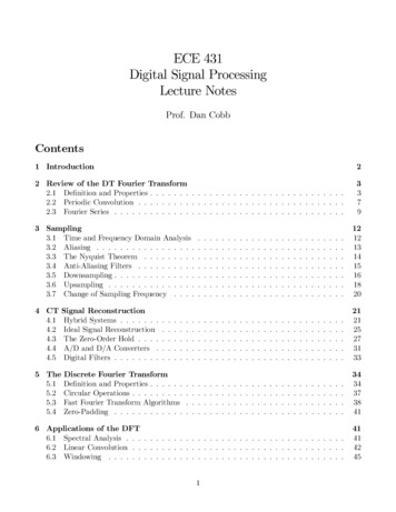
Solutions for Mixed-Signal SoC Verification Using Real Number ModelsMixed-Signal Verification ChallengesIn all types of IC design, the verification task is growing exponentially as complexity increases. For digital ICs, itis often said that functional verification now takes up 70% of the logic design phase. Add analog and mixedsignal IP, and that task gets even more complex, as illustrated in Figure 1. Even in digital verification environments,simulation is never fast enough. Yet digital RTL simulation is orders of magnitude faster than SPICE-based analogsimulation.Digital Mixed SignalHow do I verify the digitalcontent in this SoC?How do I verify the mixed-signalinterconnects?Multi-channele SequenceGeneratorCycleCallableModel (CCM)S/BMulti-LayerAHB areUVCAPBUVCInterruptControlRadioRFHow do I verify themixed-signal IP?GSAROMPHYDesignAnalogDesignMeasureRAMCPU ARTUVCSPIUVCS/BS/BMulti-ChannelSV SequenceGeneratorS/BHow do I abstractanalog behavior?Figure 1: Mixed-signal verification complexities.Analog and digital simulations use fundamentally different paradigms. While digital simulators solve logical expressions sequentially by triggering events, analog simulators must solve the entire analog system matrix at every timestep. Each element in the analog design can have an instantaneous influence on any other element in the matrix.There is no obvious signal flow in any direction, and time is continuous rather than discrete.The analog verification methodology is traditionally ad-hoc by nature, lacking the formalized methodologythat is available on the digital side. Digital verification teams now have access to executable verification plans,constrained-random stimulus generation, testbench automation, assertions, and coverage metrics. In digital design,the metric-driven verification approach, standardized for reusability as Universal Verification Methodology (UVM)1,helps engineers build confidence in the verification by increasing coverage to the desired level. On the analog side,verification is driven by directed tests run over sweeps, corners, and Monte Carlo analysis. Several analog solverstoday provide low-level device checks, but there is little or no support for verification planning or coverage metrics.As noted previously, many silicon respins stem from mixed-signal verification issues. Customer experienceshows that many design failures are caused by what some might call “highly embarrassing” errors, including pinconnection errors, inverted polarity, incorrect bus order, or pins connected to the wrong power domains. In theabsence of simple checks, such errors are often found only in lengthy analog simulation runs, if they are foundat all.With the new trend toward an Internet of Things, where every device or touch point is used to sense, process,and send data, designs involve a lot more advanced low-power techniques that are causing new complicationsfor mixed-signal verification. For example, consider a digital control logic circuit that feeds into an analog block.The logic circuit might be in a power domain where the voltage level can be one of several, depending on thepower state. Where previously, in mixed signal simulation, it was clear what voltage level should be passed to theanalog solver to represent a logic ‘1’, now, the correct level is determined by the power state. In the case of voltagescaling, it might be 1.2V for a high-performance operating mode, or 1.0V for a low-power operating mode, oreven 0.7V for a non-operating standby mode. If the power is shut off in the digital circuit, the simulator will modelwww.cadence.com3
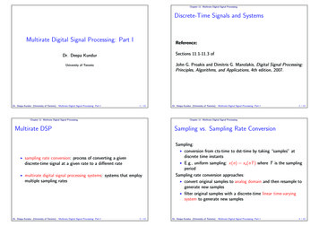
Solutions for Mixed-Signal SoC Verification Using Real Number Modelsdata corruption internal to the power domain by setting all the internal values to Xs (unknowns). If the simulatordoes not understand the impact on the analog block, it is difficult to determine whether the X states derive fromthe shutoff or from a functional failure.To address these mixed-signal low-power challenges, there has been tremendous development in extending theCommon Power Format (CPF) to support features such as power-aware connect modules to verify the low-powercontent in mixed-signal designs. These power-aware connect modules make the appropriate logical-to-electrical orelectrical-to-logical conversion based on the current power state.Mixed-Signal Block and IC-Level VerificationVerification of a mixed-signal SoC involves many different levels of abstraction. In general, transistor-levelsimulation with SPICE remains the gold standard for analog IP verification. While it provides very high accuracy,SPICE is much too slow for chip-level simulations, unless it is used very selectively.Analog behavioral modelingTo achieve reasonable simulation speeds, many mixed-signal teams employ analog behavioral modeling. Thisapproach can be 5 to 100 times faster than SPICE. The actual speedup varies widely depending on the application and the level of detail in the model. Analog behavioral models are typically written in one of the followinglanguages: Verilog-AMS—A mixed-signal modeling language based on the IEEE 1364 Verilog standard that defines analogand digital behavior, and provides both continuous-time and event-driven modeling semantics Verilog-A—A continuous-time subset of Verilog-AMS, aimed at analog design VHDL-AMS—Similar in concept to Verilog-AMS, this language provides analog and mixed-signal extensions toIEEE 1076 VHDL SystemVerilog—This language is extended with real number types, such as IEEE 1800-2012 SV-DC extensions,also known as SV-RNMThe creation of analog behavioral models can be challenging. Analog designers are in the best position to createthese models, since they are familiar with their own circuits. But many analog designers lack the programming skillsor knowledge required to construct behavioral models, and few are familiar with Verilog or VHDL. Digital designershave that familiarity, but know less about the analog circuits.Figure 2 shows the tradeoff between simulation accuracy and performance among SPICE, FastSPICE, analog behavioral models (Verilog-A/AMS and VHDL-AMS), RNM (SV-RNM), and pure digital simulation. These numbers aregeneric and can vary significantly for different applications. Note the wide range of accuracy and performance thatis possible for Verilog-AMS and VHDL-AMS behavioral models. Pure digital simulation can only represent an analogsignal as a single logic value, but it might be sufficient for connectivity checks in mixed-signal SoCs.Modeling -AVerilog-AMSVHDL-AMSRNMs are the most effectiveway to abstract AMS functioinalityfor full chip simulationRNMSV-RNMPure DigitalSimulation Performance/CapacityFigure 2: Model accuracy versus performance gain for mixed-signal simulation.www.cadence.com4
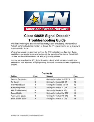
Solutions for Mixed-Signal SoC Verification Using Real Number ModelsAnother important factor is the effort required to set up a simulation and create the model. While SPICE simulations run slowly, they are relatively easy to set up. The time required to create a high-quality analog behavioralmodel, however, can range from hours to days or even weeks. RNM is restricted to a signal flow approach, whileanalog convergence is less of an issue. Typically, it takes less modeling effort to develop RNM than traditionalanalog behavioral model.The modeling goals of analog behavioral models might differ. A performance model must precisely capture criticalcircuit behavior. Functional models capture circuit behavior only to the level of detail that is needed to verify thecorrect design functionality.Mixed-Signal Verification Use ModelCo-simulation between analog and digital solvers is one methodology that has been used for mixed-signal blockand chip verification. Nonetheless, traditional co-simulation approaches have been plagued with limitations. Earlyco-simulation environments, for example, typically employed Verilog and SPICE operating in separate simulationkernels linked through inter-process communications (IPC). This separation made it difficult to keep analog anddigital simulation engines in lockstep. Users typically had to partition the circuit, deal with two netlists, and copewith two disparate debugging environments.Advanced mixed-signal verification solutions such as Cadence Virtuoso AMS Designer Simulator (Figure 3) canachieve better performance than traditional co-simulation solutions. These products utilize a single, executablekernel for both analog and digital simulation engines. These solutions also provide extensive language andmodeling support, including behavioral models in Verilog-A, Verilog-AMS, VHDL-AMS, and emerging SV-DC;transistor-level analog circuit models; and support for digital languages such as Verilog, VHDL, SystemC, e,and SV-DC.Analog DomainMixed-Signal VerificationDigital DomainTransistor-LevelSchematicGenerate RNMModelRealGenerate Verilog-AMSModelValidate Models toCircuit specsDDDSpecsDDe or SV Testbench High-performance, RNM for mixed-signal verification Models are easily ported between Virtuoso and Incisive environments Runs full-chip verification regression suites at digital speeds Benefits include increased predictability, productivity, and quality (PPQ)Figure 3: Mixed-signal verification use model.For example, Virtuoso AMS Designer links the Virtuoso custom design platform with the Cadence Incisive digitalverification platform (Figure 4). It provides an integrated GUI, integrated embedded simulation engines, anda common verification methodology (Figure 3). Virtuoso AMS Designer supports simulation engines includingVirtuoso Spectre Circuit Simulator, Virtuoso UltraSim Full-Chip Simulator, Virtuoso Accelerated Parallel Simulator,Virtuoso Spectre RF Simulation Option, and Incisive Enterprise Simulator.www.cadence.com5
Solutions for Mixed-Signal SoC Verification Using Real Number ModelsMixed-Signal IP, ICVirtuoso PlatformIntegrated GUIMixed-Signal SoCIncisive PlatformIntegrated Simulation EnginesAnalogDesignerCommon Verification MethodologyVerificationEngineerFigure 4: Example of a well-defined mixed-signal verification solution.A robust mixed-signal verification solution includes the following key features:Connect modulesDigital simulators traditionally understand only 0, 1, X, and Z, while analog simulators work with continuousvalues. Connect modules are used to translate digital signals to and from analog voltage levels. These bi-directional“connect” modules are inserted automatically to increase efficiency in an ideal mixed-signal verification solution.Power-smart connect modulesAdvanced low-power verification with a “power-smart connect module,” goes one step further, allowing theCommon Power Format (CPF) 2,which defines digital low-power structures, to be leveraged in a mixed-signalsimulation. If an analog signal’s source can be traced to a digital signal with a CPF definition, then the designer canautomatically insert a power-smart connect module. This module can distinguish between an X resulting from afunctional error and an X resulting from power shutoff, as well as different voltage levels for logic levels dependingon nominal conditions or power modes.Efficient data-flow interactionThe ability to efficiently interchange different levels of abstraction allows the design to change over time from fullbehavioral to full transistor level.RNMSupport for RNM in verification platforms allows the simulation of discrete, floating-point real numbers thatcan represent voltage levels. RNM enables users to describe an analog block as a signal-flow model, and thento simulate it in a digital solver at near-digital simulation speeds. For analog and mixed-signal block verification,RNM can be used to speed high-frequency portions of the analog signal path—which take the longest to verifyin simulation—while DC bias and low-frequency portions remain in SPICE (Figure 5). But the greatest advantageof RNM is in top-level SoC verification, where engineers can represent all electrical signals as RNM equivalentsand stay within the digital simulation environment. Hence RNM enables SoC-level regressions to cover full-chipfunctionality while maintaining high-simulation performance.www.cadence.com6
Solutions for Mixed-Signal SoC Verification Using Real Number tric MethodologyUse ModelVerilogUnifiedSimulationand DebugAnalogRNMAnalog-Centric MethodologyUse ModelVerilogVerilogA/(MS)SPICEViVaVirtuoso ADETestbenchFigure 5: Range of simulation methodologies for both analog-centric and digital-centric use models.MS-MDVIncreasing complexity in today’s mixed-signal verification leads to lots of simulation cycles on large compute farms.For SoC-level verification, it is important to see what coverage was tested and executed. Coverage-driven scenariosare commonly used by digital-verification engineers. By extending this model to mixed-signal metric-driven verification (MS-MDV), the designer can automate debugging and pass/fail checking for all stimulus and tests, as illustrated in Figure 6. This metric-driven approach has a greater probability of leading the verification flow on failuretriage and reporting.DUTVinVoutAmpMeasurement ofa dynamic signalcontrolPwr up/dnThresholdcrossing a VrefcomparatorCheck: thresholdcrossing [Vmax, Vmin]Check signal timingwithin [Vmin, Vmax][Tmin, Tmax]Figure 6: Automated analog checks.The goal of MS-MDV is to augment functional verification of mixed-signal SoCs with analog metrics. The firststep is to measure voltage, current, frequency, and gain over time. The second step comes to assertions thatinclude electrical and real number. These metrics must be collected and added to the coverage database such asSystemVerilog cover groups, e cover groups, and PSL/SVA asserts and cover. Incisive mixed-signal solution cansimulate any mix of transistor level, Verilog-AMS, RNM, and digital circuit to gather this coverage data.Bringing UVM and MDV to Mixed-Signal VerificationUVM is a standardized structured methodology for testbench creation. UVM has coding guidelines and is used forbuilding reusable verification components (UVCs) that consist of monitors and drivers. A library of building blocksfor UVC development is available for e, SystemVerilog, and SystemC. Key benefits of using UVM are code reuse,www.cadence.com7
Solutions for Mixed-Signal SoC Verification Using Real Number Modelsrandomization of stimulus, automated checking, and verification tracking using functional coverage. By leveragingRNM for analog blocks, today’s mixed-signal designs can take advantage of UVM-based SOC verification to reducerespins and bring products to market sToolsProcessesDataLogicalCommandSimulationMS Sim(AIUM)Figure 7: MS-MDV flow.A MS-MDV simulator (Figure 7) permits real number models to run natively in a pure digital environment. Userscan run full-chip verification with digital solvers for functional simulation and interconnect verification. Whenmore accuracy is needed, users can still run transistor-level simulation or analog behavioral models in the sameenvironment. Real number models are portable between digital (Incisive) and analog (Virtuoso) design environments. For example, a model can be developed and validated for an AMS block in Virtuoso, then used during SoCverification in Incisive.There are good practices of writing and validating real number models3. In recent years, tools have emerged forautomating the process of model generation and validation, including Schematic Model Generation and AMSDesign Model Validation in Virtuoso Analog Design Environment.Verification of real number models is essential. In most cases, the original transistor-level representation is used asa reference implementation. To verify the model against the reference, engineers run the same simulation on bothand compare the results. Simulation setups and test benches should be available from the block-level verificationflow. Comparisons can be done manually, or highly automated for regression testing.RNM for SoC VerificationRNM uses analog block operations as discrete real data. The models are based on signal flow and hence can bestructured as event driven. The most obvious advantage of using RNM for top-level SoC verification is that it runsnearly as fast as pure digital simulation, which is an order of magnitude faster than SPICE-based simulation oreven analog behavioral modeling. This additional speed makes full-chip verification possible for large mixed-signalSoCs. Digital simulation speeds permit nightly high-volume regression tests. With no analog engines, there are noconcerns about convergence errors.Many languages support real and wire-real, or wreal, RNM, including Verilog, SystemVerilog, VHDL, e, andVerilog-AMS. The first four support a real data type, while Verilog-AMS supports wreal.Verilog real supports the following features: Module internal use of real variables No real value ports (requires real2bits/bits2real) No support for X/Z state No multiple wreal driverVHDL real supports the following features: Real valued portswww.cadence.com8
Solutions for Mixed-Signal SoC Verification Using Real Number Models Resolution function Multiple drivers User-defined types Limited connection to analogSpecman /e real supports the following features: Mainly for testbenching Random generation, coverage, checking Direct access to analog values (receive/drive)SV-DC (SV-RNM) supports the following features: User-defined types User-defined resolution functions Definition of a nettype based on its connectivityVerilog-AMS wreal supports the following features: Easy interaction with analog Direct connection to electrical nets using E2R and R2E connect modules Disciplines association Multiple wreal driver support Ability for scope-based wreal resolution function specification Identification of high-impedance/unknown state (X/Z support)SystemVerilog IEEE 1800-2009 standard supports the following features: Real number variables I/O real ports Assign statements to real variables SVA assertions including real variablesA major bottleneck in the adoption of RNM among SoC-level verification used to be the lack of support inSystemVerilog as of IEEE 1800-2009 standard. Some of the limitations of this standard included: No real number coverage or randomization No bidirectional real number ports (no in/out) Only one driver allowed on each port connection (no support for real number resolution functions for multipledrivers) No direct support for real valued signals No inter-language connections (Verilog-AMS, SPICE)Due to these limitations, the SystemVerilog implementation of RNM required more code than wreal for the sameimplementation. Figure 8 shows the new SystemVerilog IEEE 1800-2012 standard support.www.cadence.com9
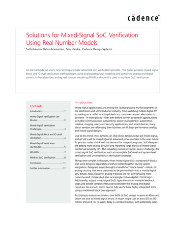
Solutions for Mixed-Signal SoC Verification Using Real Number ModelsV(out)AnalogBehavioralModel (SV)V(in)AnalogBehavioralModel (SV)AnalogBehavioralReal-Value Model (SV)Nettype?AnalogBehavioralModel (SV)AnalogBehavioralReal Variable Model (SV)Figure 8: Scenarios for UDTs and UDRs.To overcome the shortcomings of the IEEE 1800-2009 standard, SystemVerilog IEEE 1800 standardized committeeapproved the following. User-defined types (UDTs)–– Allows for real valued nets–– Allows for multi-value nets (multi-field record style) User defined resolution (UDRs)–– Functions to resolve user-defined types–– Association of function with user-defined nets Explicit Interconnects–– Type-less nets–– For connecting ports only–– No continuous or procedural assignments allowedLRM additions include: UDTs that can hold one or more real values–– New keyword: nettype–– UDTs can be used for port and net connections (unidirectional, bidirectional) UDR function for combining UDTs–– Function associated to nettype using keyword: with Type-less interconnects between nets and ports–– New keyword: interconnectFor users using Verilog-AMS wreal, Cadence has built-in wreal nettypes, such as wrealsum, wrealavg, wrealmin,and wrealmax, that enable Verilog-AMS code reuse and ease the migration to SystemVerilog (Figure 9).Data Type and Resolution FunctionModelNettype// user-defined data type Ttypedef struct (real field;bit field2;) T;UDT//user-defined resolution// function Tsumfunction automatic T Tsum(input T driver []);Tsum.field1 0.0;foreach (driver [i])Tsum.field1 driver[i].field1;endfunctionUDR// a nettype wTsum whose data type// is T and resolution function// is Tsumnettype T wTsum with Tsum//////////SV module using UDT portNotice: Although “foo p”has 2 values in its datatype,there is only 1port in this modulemodule foo (foo p);wTsum foo p;input foo p;wTsum q; // an internal netassign q foo p;endmodulemodule bar (bar p)wTsum bar p;output bar p;assign bar p T’(14.5., 1’bl);endmoduleFigure 9: SV-RNM nettype illustrations.www.cadence.com10
Solutions for Mixed-Signal SoC Verification Using Real Number ModelsRNM is not, however, a replacement for analog simulation. It is not appropriate for low-level interactions involvingcontinuous time feedback or low-level RC coupling effects. It is not intended for systems that are highly sensitive tononlinear I/O impedance interactions. In addition, real-to-electrical conversions require careful consideration. If oneis too conservative, there will be a large number of time points. If one is too liberal, there can be a loss of signalaccuracy.ConclusionFull-chip verification of large mixed-signal SoCs is a daunting task. As complexity grows, it is no longer sufficientto bolt together pre-verified analog or digital “black boxes” and hope for the best. Complex interactions betweenanalog and digital domains are resulting in more and more functional errors, which in turn are causing delayedtapeouts and silicon respins that can cost millions of dollars.Fortunately, there are solutions. A wide range of modeling and simulation approaches are available for analog anddigital circuits, and most have their place. SPICE-based simulators are still needed for verifying individual analog IPblocks. When it is time to move up to the subsystem or chip level, analog behavioral models can provide up to a100X performance increase.For top-level SoC verification, engineers can convert analog models into real number models. These models makeit possible to stay completely within the digital simulation environment, taking advantage of MDV features suchas verification planning, random test generation, coverage, and assertions. It also allows near-digital simulationspeeds. RNM with expanded support for the Verilog-AMS wreal data type and the latest SystemVerilog IEEE1800-2012 standards will further reduce the verification cycle time.Thus, an integrated
IEEE 1076 VHDL SystemVerilog—This language is extended with real number types, such as IEEE 1800-2012 SV-DC extensions, also known as SV-RNM The creation of analog behavioral models can be challenging. Analog designers are in the best position to create these