Transcription
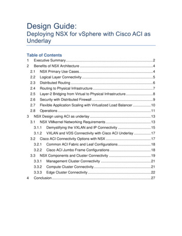
Design Guide:Deploying NSX for vSphere with Cisco ACI asUnderlayTable of ContentsExecutive Summary . 2Benefits of NSX Architecture . 42.1NSX Primary Use Cases. 42.2Logical Layer Connectivity . 52.3Distributed Routing . 62.4Routing to Physical Infrastructure . 72.5Layer-2 Bridging from Virtual to Physical Infrastructure . 82.6Security with Distributed Firewall . 92.7Flexible Application Scaling with Virtualized Load Balancer . 102.8Operations . 11NSX Design using ACI as underlay . 133.1NSX VMkernel Networking Requirements . 133.1.1Demystifying the VXLAN and IP Connectivity . 153.1.2VXLAN and VDS Connectivity with Cisco ACI Underlay . 173.2Cisco ACI Connectivity Options with NSX . 173.2.1Common ACI Fabric and Leaf Configurations . 183.2.2Cisco ACI Jumbo Frame Configurations . 183.3NSX Components and Cluster Connectivity . 193.3.1Management Cluster Connectivity . 213.3.2Compute Cluster Connectivity . 213.3.3Edge Cluster Connectivity . 22Conclusion . 27
Executive SummaryEnterprise data centers have long recognized the the tremendous benefits ofserver and storage virtualization solutions to consolidate infrastructure, reduceoperational complexity, and dynamically scale application infrastructure. Morerecently, enterprises realize that the data center network has not kept pace andremains rigid and complex. Innovations in networking can help realize the fullpotential of virtualization and the software defined data center (SDDC).VMware NSX is the network virtualization platform for SDDC. By bringing theoperational model of a virtual machine to your data center network, you cantransform the economics of network and security operations. NSX lets you treatyour physical network as a pool of transport capacity, with network and securityservices attached to VMs with a policy-driven approach. VMware NSX runs atopa physical IP fabric underlay, which can be provided and supported by anynetworking vendor. As data center networking is evolving customers are lookingto automate some of the deployments of the physical network itself. Networkingvendors such as Arista (Arista Cloud Vision At-a-glance) (Arista Cloud Vision andNSX Solution Brief), Brocade, Big Switch Networks, Cisco, Juniper, etc. all havesolutions which can help automate the physical data center network. Cisco’ssolution for an automated DC fabric is called Cisco Application CentricInfrastructure (ACI).This document provides guidance for networking and virtualization architectsinterested in taking advantage of the full functionality of VMware NSX whileutilizing Cisco ACI for underlay network functionality. While neither solution has adependency on each other, there are dependencies to ensure interoperability.This paper discusses the fundamental building blocks of NSX with VMware ESXiand recommended underlay configurations with Cisco’s ACI.Disclaimer: Following the guidelines presented in this document are veryimportant. Any deviation from the recommendations may cause challenges inthe deployment and operations of both NSX and ACI. Deviation from thestandard will cause challenges since the Cisco ACI fabric is not a typicalnetworking deployment and has additional design considerations. While NSXis agnostic to the chosen underlay, for Cisco Nexus environments it isrecommended to deploy NSX on a Nexus switches in NX-OS mode. The NXOS mode allows flexibility of topology and features supported from variety ofNexus line of switches (Nexus 56xx, 6000, 3xxx and 9xxx). The followingguides outline the benefits and design considerations: Design Guide for NSX with Cisco Nexus 9000 and UCS VMware NSX on Cisco Nexus 7000 and UCS VMware NSX for vSphere Network Virtualization Design Guide ver2.1
This document assumes that the customer has a good understanding of CiscoACI and VMware NSX. Table 1 below provides a complementary view of thecapabilities provided by VMware NSX and Cisco ACI when used in conjunction.Customers have requested such interoperability as this gives them the completebenefit of NSX such as the ability to automate networking and services andprovide secure micro-segmentation of all their workloads. Cisco ACI enablescustomers to build and control the physical underlay fabric.Table 1: VMware NSX and Cisco ACI Features Full NSX FeaturesAll NSX Functionality:o Network Virtualizationo L3 Routing in hypervisoro Micro-segmentationo Services, such as LoadBalancing, L2 VPN, etc.o Multi-site DC Integrationo DR with SRM integrationCloud Management Platformintegrations, such as native vRAintegration and OpenStack withESXi support Cisco ACI Underlay FeaturesUnderlay IP connectivityPhysical Fabric management andTroubleshooting toolsPhysical provisioningEnd Point Groups as VLANs forVMkernel Networking and EdgeRoutingCisco ACI has multiple modes of operations and to ensure that solutions areinteroperable only the design mode outlined in this document is supported. Morespecifically the following modes are not supported:1. Cisco Application Virtual Switch running on vSphere 5.5 or vSphere 6.0 isnot supported in any deployment on VMware vSphere.2. Cisco Nexus 1000v cannot be used with VMware NSX3. vSphere Distributed Switch cannot be controlled by the Cisco ACI plug-inif NSX interoperability is desired. For interoperability with NSX, VDS mustbe provisioned and managed independently from ACI.
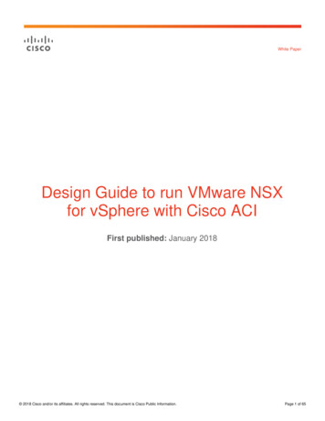
Benefits of NSX ArchitectureNSX enables users to build logical services for networking and security withouthaving to make configuration changes to the physical infrastructure. In this case,once the Cisco ACI fabric is configured to provide IP connectivity and the routingconfiguration is provisioned detailed later in this document, we can continue todeploy new services with NSX.Let us look at some examples that show how applications can be deployed withNSX for network virtualization.2.1 NSX Primary Use CasesCustomers are using NSX to drive business benefits as show in the figure below.The main themes for NSX deployments are Security, IT automation andApplication Continuity.Figure 1: NSX Use Cases Security:NSX can be used to create a secure infrastructure that can create a zerotrust security model. Every virtualized workload can be protected with afull stateful firewall engine at a very granular level. Security can be basedon constructs such as MAC, IP, ports, vCenter objects and tags, activedirectory groups, etc. Intelligent dynamic security grouping can drive thesecurity posture within the infrastructure.NSX can be used in conjunction with 3rd party security vendors such asPalo Alto Networks, Checkpoint, Fortinet, McAffee, etc. to provide acomplete DMZ like security solution within a cloud infrastructure.NSX has been deployed widely to secure virtual desktops to secure someof the most vulnerable workloads, which reside in the data center toprohibit desktop-to-desktop hacking. Automation:VMware NSX provides a full RESTful API to consume networking, security
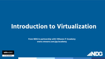
and services, which can be used to drive automation within theinfrastructure. IT admins can reduce the tasks and cycles required toprovision workloads within the datacenter using NSX.NSX is integrated out of the box with automation tools such as vRealizeautomation, which can provide customers with a one-click deploymentoption for an entire application, which includes the compute, storage,network, security and L4-L7 services.Developers can use NSX with the OpenStack platform. NSX provides aneutron plugin, which can be used to deploy applications and topologiesvia OpenStack Application Continuity:NSX provides a way to easily extend networking and security acrossvCenters and data centers. In conjunction with vSphere 6.0 customers caneasily vMotion a virtual machine across long distances and NSX willensure that the network is consistent across the sites and ensure that thefirewall rules are consistent. This essentially maintains the same viewacross sites.NSX Cross vCenter Networking can help build active – active datacenters. Customers are using NSX today with VMware Site RecoveryManager to provide disaster recovery solutions. NSX can extend thenetwork across data centers and even to the cloud to enable seamlessnetworking and security.The use cases outlined above are a key reason why customers are investing inNSX. NSX is uniquely positioned to solve these challenges as it can bringnetworking and security closest to the workload itself and carry the policies alongwith the workload. This enables customers to solve real business problems.When customers deploy NSX with Cisco ACI as the underlay they can get all ofthese incremental benefits, which would not be possible with ACI alone in anyreasonable way otherwise.Let us now take a look at some of the key technical benefits of NSX.2.2 Logical Layer ConnectivityFigure 2 shows how logical layer-2 segments can be built. Here we can observethat servers in the physical infrastructure can be in different subnets, yet anoverlay network enables VMs to be in the same subnet and layer-2 adjacent,essentially providing topology-independent connectivity and mobility beyond thestructured topology constraint imposed by physical networking.
Figure 2: Logical Layer 2NSX builds multicast-free VXLAN based overlay networks. This layer-2adjacency between the VMs can be established independent of the physicalnetwork configuration. New logical networks can be created on demand via NSX,decoupling the logical virtual network from the physical network topology.2.3 Distributed RoutingNSX enables distributed routing and forwarding between logical segments withinthe ESXi hypervisor kernel. As shown in the Figure 3, three different logicalnetworks are isolated in three different subnets. One can simply route betweenthe subnets using the distributed routing functionality provided by NSX. OSPF,BGP and static routing are supported with distributed routing.Figure 3: Distributed Routing with NSX
The key benefit of distributed routing is an optimal scale-out routing for east-westtraffic between VMs. Each hypervisor has a kernel module that is capable of arouting lookup and forwarding decision. As shown in Figure 10 above, trafficwithin a single host can be routed optimally within the host itself—even if the VMsare part of a different logical switch. The localized forwarding reduces traffic tothe ToR and potential for reduced latency as packets are switched locally inmemory.Traffic across hosts needs to go to the physical switch where ACI can make aforwarding decision based upon the destination VTEP IP.In a classic architecture all traffic would be forwarded to the switch with the SVIconfiguration; that is not necessary with the NSX distributed routing capability.The distributed router scale-out capability supports multi-tenancy in whichmultiple distributed logical router instances can be invoked to provide routingcontrol plane separation within the shared infrastructure.Figure 4: Distributed Routing Traffic Flow2.4 Routing to Physical Infrastructure
Distributed routing can meet the requirements of routing between virtualworkloads. In order to route from the logical network to the physical network,NSX can learn and exchange routes with the physical infrastructure in order toreach resources such as a database server or a non-virtualized application,which could be located on different subnet on a physical network.NSX provides a scale-out routing architecture with the use of ECMP between theNSX distributed router and the NSX Edge routing instances as shown in thefigure below. The NSX Edges can peer using dynamic routing protocols (OSPFor BGP) with the physical routers and provide scalable bandwidth.Refer to Figure 4 for Routing from Logical to Physical Workloads2.5 Layer-2 Bridging from Virtual to Physical InfrastructureSome application and service integration may require connecting VMs to physicaldevices on the same subnet (layer-2 centric workload connectivity). Examples ofthis are migrations to virtual workloads; app-tiers have hard-coded IP addressesand some workloads reside in virtual and integration with ADC appliances. Thiscan be accomplished by leveraging the native bridging functionality in NSX. Thelayer-2 bridge instance runs in a distributed manner and can bridge a VXLANsegment to a VLAN instance as shown in Figure 5 below.Figure 5: Layer-2 Bridging from Virtual to PhysicalLayer-2 bridging design considerations are covered in the NSX design guide.Additionally, one can use multicast-based HW VTEP integration if needed, with
additional design considerations.2.6 Security with Distributed FirewallNSX by default enables the distributed firewall on each VM at the vNIC level. Thefirewall is always in the path of the traffic to and from VM. The key benefit is thatit can reduce the security exposure at the root for east-west traffic and not at thecentralized location. Additional benefits of distributed firewall include: Eliminating the number of hops (helps reduce bandwidth consumption toand from the ToR) for applications traversing to a centralized firewallFlexible rules sets (rules sets can be applied dynamically, using multipleobjects available in vSphere such as logical SW, cluster and DC)Allowing the policy and connection states to move with VM vMotionDeveloping an automated workflow with programmatic security policyenforcement at the time of deployment of the VM via cloud managementplatform, based on exposure criteria such as tiers of security levels perclient or application zoneFigure 6: Micro-segmentation and Protection of TrafficAs shown in the Figure 6, the designer now has flexibility in building asophisticated policy since policy is not tied to physical topology. The policy canbe customized for inter- and intra-layer-2 segment(s), complete or partial access,as well as managing N-S rules sets that can be employed directly at the VM levelwith edge firewall being an option for the interdomain security boundary.Micro-segmentation as shown in the Figure 6 allows creating a PCI zone within ashared segment, allowing sophisticated security policies for desktops in a VDI
environment as well as eliminating the scaling limitation of centralized accesscontrol ACL management.2.7 Flexible Application Scaling with Virtualized Load BalancerElastic application workload scaling is one of the critical requirements in today’sdata center. Application scaling with a physical load balancer may not besufficient given the dynamic nature of self-service IT and DevOps styleworkloads. The load-balancing functionality natively supported in the edgeappliance covers most of the practical requirements found in deployments. It canbe deployed programmatically based on application requirements withappropriate scaling and features. The scale and application support leveldetermines whether the load balancer can be configured with layer-4 or layer-7services. Topology wise the load balancer can be deployed either in-line or insingle-ARM mode. The mode is selected based on specific applicationrequirements, however the single-ARM design offers extensive flexibility since itcan be deployed near the application segment and can be automated with theapplication deployment.Figure 7: Logical Load Balancing per ApplicationFigure 7 shows the power of a software-based load-balancer in which multipleinstances of the load-balancer serve multiple applications or segments. Eachinstance of the load-balancer is an edge appliance that can be dynamicallydefined via an API as needed and deployed in a high-availability mode.Alternatively, the load balancer can be deployed in an in-line mode, which canserve the entire logical domain. The in-line load-balancer can scale via enablingmulti-tier edge per application such that each application is a dedicated domain
for which first-tier edge is a gateway for an application, the second-tier edge canbe an ECMP gateway to provide the scalable north-south bandwidth.Figure 8: Scaling Application and Services with NSXAs one can observe from Figure 8 above, the first application block on the left isallowing a single-ARM load-balancer with distributed logical routing. The centerand the right block of the application allow an in-line load-balancer with eitherrouted or NAT capability respectively. The second-tier edge is enabled withECMP mode to allow the application to scale on demand from 10GB to 80GBand more.2.8 OperationsWith this design, the number of changes to the underlay is minimized. Most ofthe changes happen during deployment and when adding new devices.Following shows the workflow per this design guide.Cisco ACI admin performs Initial configuration for ACI Provisioning 4 EPGs for compute Provisioning 2 EPGs for EdgeCloud Admin performs the Initial configuration of NSX and setup Edge gateways.Post this initial configuration; virtual services can be setup without any change tothe underlying physical infrastructure.
Figure 9: On-time Configuration OperationsFigure 10: Recurring Consumption Operations
NSX Design using ACI as underlayThis document assumes readers have a functional knowledge of NSX and CiscoACI. Readers are strongly advised to read the design guides below for additionalcontext; they provide a detailed characterization of NSX operations, components,design, and best practices for deploying NSX.VMware NSX for vSphere Network Virtualization Design GuideDeploying NSX for vSphere with Cisco UCS and Nexus 9000 SwitchInfrastructureSpecifically, the goal of this document is to provide guidance for running NSXover Cisco ACI as the underlay fabric. The document covers connectivityrequirements for NSX including VMkernel networkingVLAN allocation and EPG configurationVXLAN Tunnel End-Point (VTEP) configurationLayer-3 peering and routing configurations for north-south traffic3.1 NSX VMkernel Networking RequirementsNSX connectivity requirement with ACI is same as any other underlay network.The four VLANs that are defined on the VMkernel interface are shown in theTable 2 below:Table 2: Infrastructure VMkernel Traffic Types and VLANVMkernel Traffic TypesFunctionsVLANIDManagementESXi and NSXmanagement plane100vMotionVM mobility101IP Storage VLANApplications &infrastructure data storeconnectivity102VXLAN Transport Zone VLANOverlay VXLAN VTEPConnectivity103VXLAN Transport Zone VLAN: This additional VMkernel interface for VXLANtraffic is created during the NSX configuration. Overall, each host is prepared
with four VMkernel networks that are presented to compute hosts and to CiscoACI.VLAN in ACI requires user to learn the end point group (EPG) concept in termsof both understanding as well configuration steps. EPGs are a fundamentalconnectivity requirement for ACI. The design option for EPGs used in thisdocument is “EPG as a VLAN” and thus for rest of the design the VLANsrequired for NSX are equivalent to an EPG required to be configured at ACI leaf.Please refer to the following for more information on using EPG as VLAN“EPG as a VLAN” section in Cisco Application Centric Infrastructure (ACI) –Endpoint Groups (EPG) Usage and Design.“Per Port VLAN” section of Cisco Application Centric Infrastructure FundamentalsLayer 2 Command Examples of Cisco Nexus CLI to Cisco APIC Mapping GuideConfiguring four EPGs (VLANs) is a one-time task in the ACI underlay for NSX tobe deployed and function. Since ACI operates as a layer 2 fabric, the four EPGscan be repeatedly used for any additional compute growth or modification to theexisting Cisco ACI fabric(such as add/move/delete of a leaf). Logical networksare created independent of the physical networks, thus eliminating the need todefine the EPG (VLAN) every time a new logical segment is added toaccommodate VM growth. The connectivity for the VMkernel interfacesoriginating from the host with 802.1Q configuration, which maps to four uniqueEPGs is shown in below figure. Note that while we named the NSX transportzone vlan “EPG VXLAN”, this is still a VLAN on ACI, not a VXLAN interface. Theactual traffic flow will be explained in more detail in the next section, 3.1.1.Figure 11: VLANs and EPG's for VMkernel Networking
For VM guest traffic the NSX Transport VLAN is used and the VMs defaultgateway is a logical interface (LIF) of the distributed logical router (DLR) asshown in section 2. The default gateway configuration for VMkernel interfacespoint to the anycast gateway on ACI, which stays consistent for every ACI leaf.The key understanding is that the default gateway of the VM is provided by NSXand is different than the gateway for the VMkernel interfaces.Apart from the 4 VLANs discussed above for compute cluster connections, NSXalso needs two VLANs for mapping route peering for north-south traffic. L3 ECMP Connectivity: Two VLANs are typically required for allowing northsouth traffic from the NSX domain to the physical world. Bridging: Optionally, NSX supports VXLAN-to-VLAN bridging for P-V or V-Vconnectivity. The number of VLAN requirements will vary based on theinstances of bridging desired.The following section demystifies standard VXLAN capabilities and the differencein the way ACI implements the physical underlay functionality. It also helps tounderstand the benefits VXLAN encapsulation originating from ESXi host tosupport logical networks and layer 3 logical routing that are agnostic to thephysical network underlay.3.1.1 Demystifying the VXLAN and IP ConnectivityNSX enables standard VXLAN encapsulation at the hypervisor level and thus ittreats ACI just like any other IP transport. The advantage of VXLANencapsulation in hypervisor is described below.VXLAN decouples the connectivity for the logical space from the physicalnetwork infrastructure. Devices connected to logical networks can leverage theentire set of network services (load balancer, firewall, NAT, etc.) independent ofhow the underlying physical infrastructure is configured. This helps solve many ofthe challenges of traditional data center deployments, such as agile &programmatic application deployment, vMotion across layer-3 boundaries, aswell as multi-tenancy support to overcome the VLAN limitation of 4094 logicalsegments.Hypervisor based encapsulation allows NSX to not only operate on a proprietaryfabric like ACI, but it also allows the freedom to change or enhance theencapsulation as its done in software. This decoupling of encapsulation allowschange in underlay and overlay independently, allowing faster adaptation oftechnology.NSX VXLAN CapabilitiesNSX VXLAN implementation offers critical enhancements to VXLAN:
NSX enables multicast free VXLAN with the help of the controller. Removingmulticast from the underlay network greatly simplifies physical networkconfiguration. The distributed discovery and efficient management of controlplane functions (MAC, VTEP and ARP table management) are relegated tohighly available clustered controllers. NSX enables VXLAN encapsulation at the kernel level in the ESXi host. ThisVXLAN encapsulated frame is nothing but a generic IP packet, which is thenrouted by any underlay switch forwarding traffic, based on the destination VTEPIP address. In addition, the underlay does not see the explosion of MACaddresses or the intensive configuration requirement for ad-hoc connectivity inthe virtual domain.These enhancements to VXLAN simplify the underlay physical network. Foradditional details about VXLAN, packet flow for various layer-2 control planediscovery, and connectivity, please refer to the VMware NSX for vSphereNetwork Virtualization Design Guide.The net effect of these enhancement is shown in below figure where ESXiencapsulate/decapsulate the VXLAN header with multicast-free replication ofBUM (Broadcast Unknown Multicast) traffic.Figure 12: VXLAN Encapsulation & Decapsulation at ESXi KernelCisco’s ACI fabric is not aware of the standard VXLAN encapsulated traffic fromNSX and treats it as normal IP traffic. ACI uses a non-standard proprietaryVXLAN header inside the fabric for inter-rack traffic with ACI span of controlterminating at the top of rack as a VLAN. A packet going across the ACI fabricwill be first encapsulated by NSX at the vSwitch with a VXLAN header for VM to
VM connectivity. When this standard VXLAN frame from hypervisor reaches theACI leaf, the ACI leaf further encapsulate the frame into a non-standardproprietary VXLAN header, which results in double encapsulation at the ACI leaffor rack-to-rack connectivity. This will look like a double encapsulated packet ifsniffed inside the fabric. Either case encapsulation overhead is minimal3.1.2 VXLAN and VDS Connectivity with Cisco ACI UnderlayVXLAN connectivity consists of two components: transport zone and VTEP. Thetransport zone is a collection of ESXi clusters participating in a single VXLANdomain. VTEP (VXLAN Tunnel End Point) is a logical interface (VMkernel) thatconnects to the transport zone for encapsulation/decapsulation of VM guesttraffic as shown in Figure 12.VDS provisioned by NSX is the only supported configuration with ACI as theunderlay. For a given cluster, only one VDS is responsible for VXLANconnectivity. The cluster design in the section below goes into the details of VDSdesign recommendation. However, there are two critical design requirements forVXLAN connectivity: VLAN ID for VXLAN, and VDS uplink Configuration. VLAN ID for VXLAN: At the NSX configuration phase, the VTEP(s) are definedwith transport zone VLAN ID; this VLAN port-group is dynamically createdduring the cluster VXLAN preparation. NSX requires the VDS dvUplinkconfiguration to be consistent per VDS and thus VLAN ID for the VXLANtransport zone has to be the same regardless of layer-2 or layer-3 topology.The detailed configuration VLAN ID mapping to a specific topology is describedin section 3.1. VDS Uplink Configuration: NSX creates a dvUplink port-group for VXLAN thatmust be consistent for any given VDS and NIC teaming policy for VXLAN portgroup must be consistent across all hosts belonging to the VDS. Typically oneVTEP is sufficient; however multiple VTEPs are also supported3.2 Cisco ACI Connectivity Options with NSXEach form of infrastructure traffic described in Table 2 (Section 3.1) requires aseparate EPG with its own bridge domain within a single tenant; similar to therequirement of a separate VLAN in a standard or non-ACI network fabric. Sinceall routing is within the NSX layer, there is no need for routing within ACI exceptin cases where NSX edge peers with ACI border leafs. For all VM traffic the DLRcomponent of NSX is the L3 gateway.
Figure 13: Distributed Routing Traffic Flow3.2.1 Common ACI Fabric and Leaf ConfigurationsThis section covers the details of connectivity requirements for various NSXcomponents and clusters required for integration with the Cisco ACI underlay.Supporting NSX on a Cisco ACI underlay requires the following to be configuredon ACI underlay:1. Jumbo frames (9K MTU) as VDS supports a max of 9K MTU2. Tenant with four EPGs for the four VLANs discussed in section 3.1Creating a Tenant in Cisco ACI: KB: Creating a Tenant, Private Network, andBridge Domain with IPv6 Neighbor DiscoveryCreating an EPG and attaching it to a port: KB: Deploying an EPG on a SpecificPort3.2.2 Cisco ACI Jumbo Frame ConfigurationsCisco ACI underlay fabric supports jumbo frame; Ensure that it is set to 9000 bychecking the value under Cisco Application Policy Infrastructure Controller(APIC) GUI under Fabric - Fabric Policies - Global Policies - Fabric L2 MTUPolicy
Reference: Cisco APIC Getting Started Guide3.3 NSX Components and Cluster ConnectivityThe NSX functions and component operation are defined in the VMware NSXfor vSphere Network Virtualization Design Guide. The reader is strongly advisedto read the document in order to follow the rationale regarding connectivity tophysical network. The NSX components are categorized in following table. TheNSX components organization and functions are mapped to appropriate cluster.The VMware NSX for vSphere Network Virtualization Design Guide calls fororganizing NSX components, compute, and management of the virtualizedenvironment. This organization principle is carried in the document and repeatedto maintain ease of user readability.Table 3: NSX Functions and Components Mapping to Cluster TypeFunctionManagement PlaneNSX ComponentsNSX ManagerRecommended ClustersDesignationManagement Cluster& vCenter ConnectivityControl PlaneNSX Controller ClusterManagement Cluster**Can be in Edge ClusterLogical Routers Control VMEdge ClusterCompute & Edge ClusterEast-WestCompute and Edge VDS kernelcomponents – VXLAN forwarding& DLR (Distributed LogicalRouter)Data PlaneEdge Service Gateway (ESG)Edge ClusterDLR Control VMEdge ClusterData PlaneNorth-SouthBridging TrafficThe VMware NSX for vSphere Network Virtualization Design Guiderecommends building three distinct vSphere
Design Guide: Deploying NSX for vSphere with Cisco ACI as Underlay Table of Contents . solutions which can help automate the physical data center network. Cisco’s solution for an automated DC fabric is called Cisco Application Centric Infrastructure (ACI). This document provides