Transcription
Chapter 5 - HydrologyChapter 5 – HydrologyPlastics Pipe Institute 105 Decker Court, Suite 825 Irving TX, 75062 469-499-1044 www.plasticpipe.org Plastics Pipe Institute 2019
5.1 HydrologyThe process of designing drainage facilities, including culverts, pipelines, and stormwatermanagement systems, requires the engineer to determine the peak rate and maximum volume offlow to be transported by the drainage facility. Numerous textbooks and manuals have beendeveloped to guide the design engineer. In addition, many agencies for which drainage facilitiesare being designed have developed their own standard procedures for hydrologic analysis.Practices do vary from state to state, and often within states, and this chapter is not intended toprovide comprehensive design procedures. It is intended to identify common procedures fordetermining the design flow. Manuals or texts that include detailed design procedures arereferenced.When considering the specific focus of the drainage engineer, hydrology is the science which dealswith estimating the rate of precipitation or rainfall, estimating the spatial distribution of the rainfall,and quantifying the flow or runoff (both peak rate and total volume) that reaches a particularlocation. This location is labeled the “point of solution.” The point of solution can be a catchbasin, inlet, culvert entrance, or any other point within a watershed where detailed analysis isdesired.There are several factors that directly impact runoff. These include the rainfall intensity, the typeof ground cover of the drainage area, the time of concentration for the rainfall event, and the sizeof the contributing drainage area.It is important to note that estimating the above parameters requires significant experience andjudgement. Additionally, different techniques commonly used to estimate runoff can produceconsiderably different results for identical hydrologic design parameters. Therefore, the level ofeffort spent on estimating the runoff, and the storm interval selected for the design of a drainagefacility must be commensurate with the risk of damage from flooding.5.2 Rainfall Intensity, Duration, and Frequency DataRainfall is typically measured as the total amount (in. or cm) of rainfall coupled with the durationof the rainfall event. Rainfall intensity, measured in inches or cm per hour, is dependent upon theduration of the rainfall and the frequency of the storm event. Short duration storms and storms oflonger return periods are often more intense than longer, more frequent storms.When describing rainfall events, both the duration and frequency are needed to fully describe therainfall intensity. The frequency of the storm event, or recurrence interval, is a statement of thestatistical likelihood of a rainfall event occurring in a given year. Consider a rainfall event with a10-year recurrence interval. It would indicate that there is a 0.10 or 10% chance of a rainfall eventof this intensity and duration occurring in any given year. It does not indicate that this event willonly occur once in every 10-years, but rather that it will occur every 10 years on average. Thedesign frequency used in the design of drainage facilities is typically provided by the facility owneror jurisdictional regulatory agency. Typical design year frequencies for various roadway classesare provided in Table 5.1.Chapter 5 –HydrologyPlastics Pipe Institute 105 Decker Court, Suite 825 Irving TX, 75062 469-499-1044 www.plasticpipe.org Plastics Pipe Institute 2019Page 2 of 20
Table 5.1: Design storm selection guidelines (1)Rainfall intensity/duration/frequency (IDF) curves are statistically-developed from rain gaugerecordings of rainfall data over time. IDF curves are available from the National Weather Service,most State DOTs, local flood control agencies, and other governmental agencies. The NationalOceanic and Atmospheric Administration (NOAA) has developed a web-based PrecipitationFrequency Data Server. This website is based on NOAA Atlas 14, Precipitation-Frequency Atlasof the United States (2). The website provides the user with rainfall intensity, duration, andfrequency data along with rainfall confidence intervals. Figure 5.1 illustrates a typical IDF curve.Chapter 5 –HydrologyPlastics Pipe Institute 105 Decker Court, Suite 825 Irving TX, 75062 469-499-1044 www.plasticpipe.org Plastics Pipe Institute 2019Page 3 of 20
Figure 5.1: Typical IDF curve (3)5.3 Estimating Time of ConcentrationThe time of concentration is the time required for stormwater runoff to travel from the mosthydraulically distant point in a watershed to the point of solution. The time of concentration (tt) iscomprised of three distinct components: overland flow time (to); shallow concentrated flow time(ts); and, concentrated flow time (tc). There are many ways to estimate tt and formulas exist for theprediction of all three subcomponents of the time of concentration. The time of concentration isthe total time for water to move through each flow regime until it reaches the point of solution.Time of Overland FlowOverland flow time to is the first component of the time of concentration. It typically occurs at themost remote point in the watershed and is characterized by sheet flow. It is thought to occur forno more than 300 ft (91 m), though some limit no further than 100 ft (31 m).Chapter 5 –HydrologyPlastics Pipe Institute 105 Decker Court, Suite 825 Irving TX, 75062 469-499-1044 www.plasticpipe.org Plastics Pipe Institute 2019Page 4 of 20
Kirpich EquationThe time of concentration of overland flow to can be estimated from the Kirpich equation, as givenin Eqn. 5.1:𝑡" 0.00013 𝐿*. 𝑆 -*./0(Eqn. 5.1)where:to L S H concentration time, hrs;the longest length of water travel, ft (m);ground surface slope H/L, ft/ft (m/m); and,difference in elevation between the most remote point on thebasin and the collection point, ft. (m).The Kirpich empirical equation is normally used for natural drainage basins with well-definedoverland flow routes along bare soil. For overland flow on impervious surfaces, the to obtainedshould be reduced by 60%. For overland flow on grass surfaces, the computed to should beincreased by 100%.Kinematic Wave EquationThe kinematic wave equation may also be used to determine to. Eqn. 5.2 shows the form:𝑡" *.1.234.5 6274.5 6(9 4.: )( 4. )(Eqn. 5.2)where:to n L i S travel time, minutes;Manning’s roughness coefficient;flow length, ft (m);rainfall intensity, inch/hr (cm/hr); and,slope of hydraulic grade line (land slope), ft/100 ft (m100).Obtaining a solution for the kinematic wave equation is an iterative procedure because the to is afunction of the rainfall intensity, while the rainfall intensity is a function of the total time ofconcentration.Manning’s roughness coefficient is a function of the depth of flow. For very shallow depths, suchas overland flow, a modified roughness coefficient must be utilized and typical values are providedin Table 5.2.Chapter 5 –HydrologyPlastics Pipe Institute 105 Decker Court, Suite 825 Irving TX, 75062 469-499-1044 www.plasticpipe.org Plastics Pipe Institute 2019Page 5 of 20
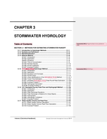
Table 5.2 Manning's roughness coefficient (n) for overland sheet flow (4)Upland MethodThe Upland method is a graphical solution for finding the average overland flow velocity and canbe used for overland flow in basins with a variety of land covers. This method relates to to thebasin slope and to the length and type of ground cover. A graphical solution for finding the averageoverland flow velocity can be obtained from Figure 5.2. The to is commonly estimated as thelongest length of flow travel divided by the average velocity of flow.Chapter 5 –HydrologyPlastics Pipe Institute 105 Decker Court, Suite 825 Irving TX, 75062 469-499-1044 www.plasticpipe.org Plastics Pipe Institute 2019Page 6 of 20
Figure 5.2: Average velocities for estimating travel time for shallow concentrated flow (5)Chapter 5 –HydrologyPlastics Pipe Institute 105 Decker Court, Suite 825 Irving TX, 75062 469-499-1044 www.plasticpipe.org Plastics Pipe Institute 2019Page 7 of 20
Shallow Concentrated FlowAs runoff moves towards the point of solution, it concentrates into rills and gullies. Flow of thistype is more efficient than overland flow and occurs with increased velocity. This type of flow isidentified as shallow concentrated flow. The velocity of ts can be determined using the equationshown in Eqn. 5.3:𝑉 3.281 𝑘 𝑆(Eqn. 5.3)where:V K S Velocity, ft/sec. (m/sec);intercept coefficient (seen in Table 5.3); and,overland slope, ft/100 ft (m/100 m).Chapter 5 –HydrologyPlastics Pipe Institute 105 Decker Court, Suite 825 Irving TX, 75062 469-499-1044 www.plasticpipe.org Plastics Pipe Institute 2019Page 8 of 20
Table 5.3: Intercept coefficients for shallow concentrated flow (4)Once the velocity of flow has been determined the time of shallow concentrated flow ts can becomputed as shown in Eqn. 5.4:3𝑡C D* E(Eqn. 5.4)where:ts L V time of shallow concentrated flow, min;overland flow length, ft (m); and,velocity of overland flow, ft/sec (m/sec).Concentrated FlowThe concentrated flow, tc, is flow that is confined by sidewalls, natural or constructed, and free totravel under the influence of gravity. When runoff flows in an open channel or pipe, the length ofthe channel or pipe and the velocity are used to determine the time of concentration, tt, for thatportion of the watershed. Manning’s equation may be used to determine the average velocity ofopen channel flow, as shown in Eqn. 5.5:𝑉 F.G1 H I C K I7(Eqn. 5.5)where:V r P s n velocity, ft/sec (m/sec);hydraulic radius in ft (equal to the cross-sectional area of the flowdivided by the wetted perimeter, ft2/P);wetted perimeter, ft (m);slope of the channel, ft/ft (m/m); and,Manning’s roughness coefficient for open channel flow (seen inTable 5.4).Chapter 5 –HydrologyPlastics Pipe Institute 105 Decker Court, Suite 825 Irving TX, 75062 469-499-1044 www.plasticpipe.org Plastics Pipe Institute 2019Page 9 of 20
Table 5.4: Typical values for Manning's roughness coefficient (4)Typical Values for Manning's Roughness CoefficientConduit MaterialClosed ConduitsConcrete Pipe (Smooth)Concrete Boxes (Smooth)Spiral Rib Metal Pipe (Smooth)Corrugated Metal Pipe (Helical Corrugations 2-2/3 X 1/2 in)Corrugated Metal Pipe (Helical Corrugations 6 X 1 in)CorrugatedMetalPipe,Pipe-Arch and Box (Annular Corrugations 2-2/3 X 1/2 in)Corrugated Metal Pipe, Pipe-Arch and Box (Annular Corrugations)Corrugated Metal Pipe, Pipe-Arch and Box (Annular Corrugations 5 X 1in)Corrugated Metal Structural Plate (Annular Corrugations 6 X 2 in)Corrugated Metal Structural Plate (Annular Corrugations 9 X 2-1/2 in )Corrugated Polyethylene (Smooth)Corrugated Polyethylene (Corrugated)Polyvinyl chloride (PVC) (Smooth)Open ChannelsLined channelsAsphaltBrickConcreteRubble or riprapVegetalExcavated or dredgedEarth, straight and uniformEarth, winding, fairly uniformRockUnmaintainedNatural channels (minor streams, top width at flood stage 100 ft)Fairly regular sectionIrregular section with poolsManning's 0.033-0.0370.009-0.0150.018-0.0250.009-0.0110.013 - 0.0170.012 - 0.0180.011 - 0.0200.020 - 0.0350.030 - 0.4000.020 - 0.0300.025 - 0.0400.030 - 0.0450.050 - 0.1400.030 - 0.0700.040 - 0.100Once the velocity of concentrated flow has been determined, the tc can be computed using thesame procedure as described for shallow concentrated flow.5.4 Estimating Rainfall RunoffIn many situations, it is sufficient to calculate the peak rate of runoff and the distribution of runoff,as a function of time is not necessary. There are many methods available for determining the peakChapter 5 –HydrologyPlastics Pipe Institute 105 Decker Court, Suite 825 Irving TX, 75062 469-499-1044 www.plasticpipe.org Plastics Pipe Institute 2019Page 10 of 20
rates of stormwater runoff. Two of the most popular are the Rational Method and the NRCSmethod.Rational MethodThe rational method has been used to estimate runoff since the late 1800’s, named for the rationalapproach to estimating runoff. When using the rational method, the peak runoff is found by therelationship between the size of the drainage area, the amount of rainfall, and the proportion ofrainfall that is converted into runoff. A fundamental assumption of the rational method is that therainfall intensity is uniform over the entire contributing drainage area and lasts for the entire stormduration. This assumption limits the applicability of the rational method to relatively smalldrainage basins, which are usually considered to be in the range of 200 to 300 acres (81 to 121hectares).The rational method takes the form:𝑄 𝐶𝑖𝐴(Eqn. 5.6)where:Q C i A peak rate of runoff, cfs (cms);runoff coefficient;rainfall intensity, for selected recurrence interval and duration equalto the time of concentration in./hr (cm/hr); and,area, acres (hectares).The runoff coefficient, C, is the percentage of rainfall which is converted into runoff. The reasonsfor rainfall not being converted into runoff include evapotranspiration, infiltration, and localizeddepression storage. Many factors or variables affect the magnitude of C, including the slope ofthe ground, type of ground cover, soil moisture, travel length and velocity of overland flow, travellength and velocity of stream flow, rainfall intensity, and other phenomena. Generally, it isnecessary to use higher C values for greater rainfall intensities and for steeper slopes. The selectionof an appropriate C value requires careful judgment on the part of the design engineer. Typicalranges for C values can be found in Table 5.5.Chapter 5 –HydrologyPlastics Pipe Institute 105 Decker Court, Suite 825 Irving TX, 75062 469-499-1044 www.plasticpipe.org Plastics Pipe Institute 2019Page 11 of 20
If a watershed is comprised of several subareas of differing land use, a weighted C value shouldbe computed as shown in Eqn. 5.7:𝐶P USVK RS TS USVK TS(Eqn. 5.7)where:Cw Ci Ai n weighted runoff coefficient;runoff coefficient for ith subarea;area of ith subarea, acres (hectares); and,number of unique subareas.The engineer responsible for the design of drainage facilities must anticipate and assess the mostlikely effects of future development of all of the land in the watershed of interest. Urbandevelopment will generally increase the volumes of stormwater runoff due to reduced infiltrationand greater peak discharges, due to decreased flow travel time.Chapter 5 –HydrologyPlastics Pipe Institute 105 Decker Court, Suite 825 Irving TX, 75062 469-499-1044 www.plasticpipe.org Plastics Pipe Institute 2019Page 12 of 20
Table 5.5: Runoff coefficient for various land uses (6)NRCS Method (5)In 1964, the Natural Resources Conservation Service (NCRS) developed a computer program forwatershed modeling. That watershed model was presented in Technical Release 20. The model isused for watershed evaluation and flood plain studies. To estimate runoff and peak rates of flowin small watersheds, a simplified method was developed and presented in Technical Release 55TR-55 (5). For small watersheds, stream flow records are often unavailable, and when they areavailable, urban development may result in inaccurate statistical analysis. The TR-55 methodallows for the development of hydrologic models using watershed characteristics to estimate peakdischarge from the watershed.Chapter 5 –HydrologyPlastics Pipe Institute 105 Decker Court, Suite 825 Irving TX, 75062 469-499-1044 www.plasticpipe.org Plastics Pipe Institute 2019Page 13 of 20
The TR-55 model begins with a rainfall amount uniformly imposed on a watershed for a 24-hourdistribution period. The period of 24 hours was used because of the availability of daily rainfalldata that could be used to estimate 24-hour rainfall amounts.Rainfall is then converted into mass rainfall using a runoff curve number (CN). The runoff curvenumbers developed in TR-55 are based upon watershed characteristics including soil type, typeand amount of plant cover, amount of impervious area, runoff interception, and surface storage.Runoff is then transformed into a hydrograph using a graphical or tabular computation method.The result is a peak discharge or design flow that can be used for the design of drainage structures.The TR-55 model can be used for any location in the United States. It provides a nationallyconsistent method of determining peak flow and can be used to check of peak flow computationsmade by other methods. If major discrepancies are found, a more thorough evaluation of thecomputations may be warranted.Hydrologic Soil GroupSoils are classified into hydrologic soil groups (HSG) to indicate the rate of infiltration and therate at which water moves within the soil. The HSGs are defined in TR-55 as follows:Group A soils have low runoff potential and high infiltration rates even when thoroughly wetted.They consist mainly of deep, well-to-excessively drained sands or gravels and have a high rate ofwater transmission (i.e., greater that 0.30 in./hr (0.76 cm/hr));Group B soils have moderate infiltration rates when thoroughly wetted and consist mostly ofmoderately-deep to deep, moderately-well to well-drained soils with moderately-fine tomoderately-coarse textures. These soils have a moderate rate of water transmission (i.e., 0.15 to0.30 in./hr (0.38 to 0.76 cm/hr));Group C soils have low infiltration rates when thoroughly wetted and consist mainly of soils witha layer that impedes downward movement of water, and soils with moderately-fine to fine texture.These soils have a low rate of water transmission (i.e., 0.05 to 0.15 in./hr (0.13 to 0.38 cm/hr));and,Group D soils have high runoff potential. They have very low infiltration rates when thoroughlywetted and consist primarily of clay soils with a high swelling potential, soils with a permanenthigh water table, soils with a clay pan or clay layer at or near the surface, and shallow soils overnearly impervious material. These soils have a very low rate of water transmission (i.e., 0 to 0.05in./hr (0 to 0.13 cm/hr)).Runoff Curve NumberThe Runoff Curve Number (CN) is used to define the amount of rainfall which is not convertedinto runoff. CN values vary from 0 to 100. The CN for various ground covers and HSGs havebeen tabulated by NRCS and are widely available in engineering publications. Composite CNscan be calculated for drainage areas of varying soil cover and HSG using a weighting proceduresimilar to that which is used for the rational method.Chapter 5 –HydrologyPlastics Pipe Institute 105 Decker Court, Suite 825 Irving TX, 75062 469-499-1044 www.plasticpipe.org Plastics Pipe Institute 2019Page 14 of 20
Initial AbstractionInitial abstraction (Ia) is the total of all losses before runoff begins. It includes water retained insurface depressions, water intercepted by vegetation, evaporation, and infiltration. The Ia is highlyvariable, but generally is correlated with soil and cover parameters. Through the studies conductedon many small agricultural watersheds, Ia was found to be approximated by the empirical equationshown in Eqn. 5.8:𝐼X 0.2𝑆(Eqn. 5.8)Where CN and S are related by:𝑆 1000 10𝐶𝑁The Ia is dependent upon the CN value only. Using the calculated CN, the Ia can be found in tabularform in TR-55 (5) or by using the relationship defined in Eqn. 5.8.Peak Unit DischargeThe peak unit discharge, qu, is an empirical parameter which considers the rainfall distribution, thetime of concentration, and initial losses. The TR-55 model provides graphical methods ofdetermining the qu, by using the following information:1. Determine the time of concentration. This is the summation of the flow travel time througheach consecutive segment of the watershed area. Travel time for sheet flow, shallowconcentrated flow, and open channel flow can be calculated as discussed earlier in thischapter.2. Determine the rainfall distribution. Different rainfall distributions can be developed foreach watershed to emphasize the critical rainfall duration for the peak discharges.However, in order to avoid the use of a different set of rainfall intensities for each drainagearea size, it is common practice in rainfall runoff analysis to develop a set of syntheticrainfall distributions. For the small-sized drainage areas, a storm period of 24 hours isappropriate for determining runoff volumes (even though 24 hours is a longer period thanneeded to determine the peak runoff).3. The TR-55 model provides synthetic rainfall distributions for various intensities. Ageographic depiction of rainfall distribution types is provided in TR-55. Types I, IA, II,and III are dependent upon the location of the watershed within the United States.4. Determine the relationship Ia/P where P is the rainfall depth for the watershed measured inin. or cm. Then rainfall with a 24-hour duration and at various intensities can be obtainedfrom the NOAA Precipitation Frequency Data Server or from local weather or waterresource agencies.Chapter 5 –HydrologyPlastics Pipe Institute 105 Decker Court, Suite 825 Irving TX, 75062 469-499-1044 www.plasticpipe.org Plastics Pipe Institute 2019Page 15 of 20
Excess RainfallExcess rainfall is the depth of rainfall that is potentially available for runoff, after adjusting forinitial losses. It should be computed as shown in Eqn. 5.9:([-\ )I𝑄 ([-\ ]) ](Eqn. 5.9)where:Q P S Ia runoff, in. (mm) (note: not the same parameter, Q, used for peak rateof runoff in the rational method);rainfall, in. (mm);potential maximum retention after runoff begins, in. (mm); and,initial abstraction, in. (mm).Peak DischargePeak discharge can be computed using Eqn. 5.10:𝑄 𝑞a 𝐴b 𝑄(Eqn. 5.10)where:Qp qu peak discharge, cfs (cms);unit peak discharge, cfs per square mile per in. (cms per square kmper cm);Am drainage area, square miles (square km); and,Q direct runoff, in. (mm).5.5 Rainfall Runoff HydrographA rainfall runoff hydrograph provides the relationship between the discharge and the time for theentire duration of a storm event. A typical hydrograph is presented inFigure 5.3. The shapeof the hydrograph differs from basin to basin. It is a function of the physical characteristics of thedrainage basin, rainfall intensities and distribution pattern, land uses, soil type, and the initialmoisture condition of the soil.Chapter 5 –HydrologyPlastics Pipe Institute 105 Decker Court, Suite 825 Irving TX, 75062 469-499-1044 www.plasticpipe.org Plastics Pipe Institute 2019Page 16 of 20
Figure 5.3: Typical runoff hydrographThe types of hydrographs are typically either direct or synthetic. A direct hydrograph is based onthe statistical analysis of long-term rainfall records within a given watershed. This method isgenerally applicable to very large watersheds and is only applicable to that specific watershed. Asynthetic hydrograph represents an estimate of the discharge versus time relationship developedto approximate the response of a typical watershed in a given geographic location. The synthetichydrograph is then converted to represent a unit of 1 in. (2.5 cm) of precipitation. For the vastmajority of projects, the use of synthetic hydrographs is suitable.The NRCS has developed unit synthetic hydrographs for each of the four geographic locations.The NRCS unit hydrograph is converted to represent a unit of 1 in. (2.5 cm) of precipitation andfor 1 square mile (2.6 square km) of drainage area. Each time step value of the unit hydrograph isthen multiplied by the peak discharge, Qp, to determine the ordered pairs (time, discharge) for therunoff hydrograph.5.6 Computer ModelsThe NRCS has provided a computer version of the TR-55 for use in computing peak rates of runoffand runoff hydrographs. For large, complex watersheds and for high-profile or high-risk culvertinstallations, it may be necessary to utilize a sophisticated computer solution for determiningrunoff hydrographs and peak runoff rates.The U.S. Army Corps of Engineers Hydraulics Engineering Center has developed a set ofhydraulic models for use in watershed management. The Hydraulic Engineering CenterHydrologic Modeling System (HEC-HMS) is widely used for modelling watershed hydrology andis capable of simulating a large number of separate sub-shed areas, actual storm events, infiltrationmethods, and methods for routing flows from point-to-point within the watershed (7).Both the NRCS and U.S. Army Corps of Engineers software products are available for freedownload from their respective governmental agency websites. The TR-55 model is accessiblefrom www.nrcs.usda.gov, while the HEC-HMS program can be downloaded fromhec.usace.army.mil. However, it is important to note that the results from computer-based modelsChapter 5 –HydrologyPlastics Pipe Institute 105 Decker Court, Suite 825 Irving TX, 75062 469-499-1044 www.plasticpipe.org Plastics Pipe Institute 2019Page 17 of 20
must be based on sound input values and should be reviewed for accuracy by an experienced designengineer.5.7 Example ProblemGiven:A parcel of land is scheduled for development and has the following land use characteristics forthe pre- and post-developed conditions, as shown in Tables 5.6 and 5.7.Table 5.6: Example problem – Pre-developed conditionsLand UseArea(acres)51520Forested AreaMeadowTotal Runoff Coefficient Time of(C)(min)0.200.2520ConcentrationTable 5.7: Example problem - Post-developed conditionsLand UseArea(acres)0.51.51.516.520Forested AreaMeadowPavedSingle Family ResidentialTotal Runoff Coefficient Time of(C)(min)0.200.250.900.4015ConcentrationFind:The peak 10-year runoff for the pre- and post-developed condition using the rational method1. Use the equation, 𝐶P developed conditions:𝐶P 0(*.c*) F0(*c0)c*𝐶P USVK TS, and determine the weighted runoff coefficient for pre- 0.2382. Use the equation, 𝐶P developed conditions: USVK RS TS USVK RS TS USVK TS, and determine the weighted runoff coefficient for post-*.0(*.c*) F.0(*.c0) F.0(*.1*) FD.0(*.G*)c* 0.421Chapter 5 –HydrologyPlastics Pipe Institute 105 Decker Court, Suite 825 Irving TX, 75062 469-499-1044 www.plasticpipe.org Plastics Pipe Institute 2019Page 18 of 20
3. Utilize Figure 5.1 to determine the rainfall intensity, I, for a 10-year recurrence interval for thepre- and post-developed conditions:i10pre 3.6 in./hr (10.7 cm/hr)i10post 4.2 in./hr (9.1 cm/hr)4. Utilize the rational equation, 𝑄 𝐶 𝑖 𝐴, and determine the peak 10-year runoff for the predeveloped conditions:𝑄 0.238(3.6)(20) 17.1 𝑐𝑓𝑠 (0.5 cms)5. Utilize the rational equation, 𝑄 𝐶 𝑖 𝐴, to determine the peak 10-year runoff for the postdeveloped condition:𝑄 0.421(4.2)(20) 35.4 𝑐𝑓𝑠 (1.0 cms)The proposed land development results in the doubling of the peak discharge from the parcel,primarily because land development typically increases the imperviousness of the land. Thiscreates an effect by increasing the proportion of runoff that travels overland, as evidenced by therational equation and the increased runoff coefficient value. The land use conversion alsoincreased the time of concentration, which resulted in an increase in the rainfall intensity.Chapter 5 –HydrologyPlastics Pipe Institute 105 Decker Court, Suite 825 Irving TX, 75062 469-499-1044 www.plasticpipe.org Plastics Pipe Institute 2019Page 19 of 20
References1. AASHTO. “AASHTO Drainage Manual,” American Associate of State Highway andTransportation Officials, 444 North Capitol Street, N.W., Ste. 249, Washington, D.C. 20001, 2014.2. NOAA. “Atlas 14 Point Precipitation Frequency Estimates,” NOAA Atlas 14, Vol. 8, Version2, U.S. Department of Commerce, April 21,2017.https://hdsc.nws.noaa.gov/hdsc/pfds/pfds map cont.html.3. ODOT. “Location and Design Manual, Volume 2 Drainage Design,” Ohio Department ofTransportation, Columbus, OH, January 2014.4. FHWA. “Urban Drainage Design Manual,” Hydraulic Engineering Circular No. 22, FederalHighway Administration, Washington DC, 2001.5. NRCS. “Urban Hydrology for Small Watersheds,” United States Department of Agriculture,Technical Release 55, June 1986.6. FHWA. “Highway Hydrology,” Hydraulic Design Series No. 2, Federal HighwayAdministration, Washington DC, 1996.7. United States Army Corps of Engineers. “HEC-HMS Downloads,” Hydrolic EngineeringVenter, Version 4.3, September 2018.Chapter 5 –HydrologyPlastics Pipe Institute 105 Decker Court, Suite 825 Irving TX, 75062 469-499-1044 www.plasticpipe.org Plastics Pipe Institute 2019Page 20 of 20
with estimating the rate of precipitation or rainfall, estimating the spatial distribution of the rainfall, and quantifying the flow or runoff (both peak rate and total volume) that reaches a particular . Pipe-Arch and Box (Annular Corrugations 2-2/3 X 1/2 in) 0.022-0.027 Corrugated Metal Pipe, Pipe