Transcription
An AADL-DEVS Framework for Cyber-PhysicalSystems Modeling and Simulation Supported with anIntegrated OSATE and DEVS-Suite ToolsHessam S. SarjoughianEhsan M. AhmadCollege of Computing and Informatics,Saudi Electronic University,Riyadh, Saudi ArabiaArizona Center for Integrative Modeling &SimulationSchool of Computing, Informatics, and DecisionSystems Engineering,Arizona State University, Tempe, Arizona, USAMarch 9, 2020
Contents1. Introduction22. Background22.1. System-Theoretic Discrete-Event Simulation . . . . . . . . . . . . . . . . . . . . . . . . . . . .22.1.1. Atomic DEVS Model . . . . . . . . . . . . . . . . . . . . . . . . . . . . . . . . . . . . .22.1.2. Coupled DEVS Model . . . . . . . . . . . . . . . . . . . . . . . . . . . . . . . . . . . .32.2. DEVS-Suite Simulator . . . . . . . . . . . . . . . . . . . . . . . . . . . . . . . . . . . . . . . .42.3. Architecture Analysis & Design Language . . . . . . . . . . . . . . . . . . . . . . . . . . . . . .43. AADL-DEVS Framework63.1. AADL Modeling . . . . . . . . . . . . . . . . . . . . . . . . . . . . . . . . . . . . . . . . . . .63.1.1. Structure Modeling . . . . . . . . . . . . . . . . . . . . . . . . . . . . . . . . . . . . . .73.1.2. Data Modeling . . . . . . . . . . . . . . . . . . . . . . . . . . . . . . . . . . . . . . . .73.2. Behavior Modeling using DEVS Annex . . . . . . . . . . . . . . . . . . . . . . . . . . . . . . .83.2.1. Variables Section . . . . . . . . . . . . . . . . . . . . . . . . . . . . . . . . . . . . . . .93.2.2. States Section . . . . . . . . . . . . . . . . . . . . . . . . . . . . . . . . . . . . . . . . .93.2.3. Behavior Section . . . . . . . . . . . . . . . . . . . . . . . . . . . . . . . . . . . . . . .103.2.4. External Transition Function . . . . . . . . . . . . . . . . . . . . . . . . . . . . . . . . .103.2.5. Internal Transition Function . . . . . . . . . . . . . . . . . . . . . . . . . . . . . . . . .113.2.6. Output Function . . . . . . . . . . . . . . . . . . . . . . . . . . . . . . . . . . . . . . .123.2.7. Test Input Declaration . . . . . . . . . . . . . . . . . . . . . . . . . . . . . . . . . . . .133.3. Code Generation for Simulation . . . . . . . . . . . . . . . . . . . . . . . . . . . . . . . . . . .133.3.1. Data Classes Generation . . . . . . . . . . . . . . . . . . . . . . . . . . . . . . . . . . .143.3.2. Structural Code Generation . . . . . . . . . . . . . . . . . . . . . . . . . . . . . . . . . .183.3.3. Behavioral Code Generation . . . . . . . . . . . . . . . . . . . . . . . . . . . . . . . . .193.3.4. Code Generation for Composite Components . . . . . . . . . . . . . . . . . . . . . . . .234. A Case Study of Isolette Thermostat System234.1. Manage Regulator Interface Function . . . . . . . . . . . . . . . . . . . . . . . . . . . . . . . .254.1.1. Data Specification . . . . . . . . . . . . . . . . . . . . . . . . . . . . . . . . . . . . . .254.1.2. Functional Requirements Specification . . . . . . . . . . . . . . . . . . . . . . . . . . .265. Manage Regulator Interface Modeling & Simulation under the AADL-DEVS Framework265.1. Structure and Data Modeling . . . . . . . . . . . . . . . . . . . . . . . . . . . . . . . . . . . . .275.1.1. Manage Interface Failure & Desired Range . . . . . . . . . . . . . . . . . . . . . . . . .275.1.2. Manage Display Temperature . . . . . . . . . . . . . . . . . . . . . . . . . . . . . . . .281
5.1.3. Manage Status . . . . . . . . . . . . . . . . . . . . . . . . . . . . . . . . . . . . . . . .295.1.4. Manage Regulator Interface . . . . . . . . . . . . . . . . . . . . . . . . . . . . . . . . .305.2. Behavior Modeling . . . . . . . . . . . . . . . . . . . . . . . . . . . . . . . . . . . . . . . . . .315.2.1. Manage Interface Failure & Desired Range . . . . . . . . . . . . . . . . . . . . . . . . .315.2.2. Manage Display Temperature . . . . . . . . . . . . . . . . . . . . . . . . . . . . . . . .325.2.3. Manage Status . . . . . . . . . . . . . . . . . . . . . . . . . . . . . . . . . . . . . . . .345.2.4. Manage Regulator Interface . . . . . . . . . . . . . . . . . . . . . . . . . . . . . . . . .355.3. Code Generation for DEVS Simulation . . . . . . . . . . . . . . . . . . . . . . . . . . . . . . .355.3.1. Manage Interface Failure & Desired Range . . . . . . . . . . . . . . . . . . . . . . . . .355.3.2. Manage Display Temperature . . . . . . . . . . . . . . . . . . . . . . . . . . . . . . . .405.3.3. Manage Status . . . . . . . . . . . . . . . . . . . . . . . . . . . . . . . . . . . . . . . .435.3.4. Manage Regulator Interface . . . . . . . . . . . . . . . . . . . . . . . . . . . . . . . . .456. Simulation using DEVS-Suite466.1. Atomic Model Simulation . . . . . . . . . . . . . . . . . . . . . . . . . . . . . . . . . . . . . .466.2. Coupled Model Simulation . . . . . . . . . . . . . . . . . . . . . . . . . . . . . . . . . . . . . .467. Related Work478. Conclusion and Future Work48A DEVS Annex Syntax Card50A1. Lexical Elements . . . . . . . . . . . . . . . . . . . . . . . . . . . . . . . . . . . . . . . . . . .50A2. Grammar Productions . . . . . . . . . . . . . . . . . . . . . . . . . . . . . . . . . . . . . . . . .512
List of Figures1Graphical notation for Atomic and Coupled Models in DEVS-Suite Simulator . . . . . . . . . . .42Graphical notation for hierarchical modeling in AADL . . . . . . . . . . . . . . . . . . . . . . .53AADL-DEVS Framework . . . . . . . . . . . . . . . . . . . . . . . . . . . . . . . . . . . . . .64AADL to DEVS Code Generation Engine (ADCoDE) Workflow . . . . . . . . . . . . . . . . . .145Class diagram for primitive data types . . . . . . . . . . . . . . . . . . . . . . . . . . . . . . . .156Class diagram for compound data types . . . . . . . . . . . . . . . . . . . . . . . . . . . . . . .157Newly generated class current speed being used within regulate speed class . . . . . . . . . . .188Isolette Context Diagram with Controller (Thermostat) and Physical Environment (Air) . . . . . .249Regulate Temperature Function . . . . . . . . . . . . . . . . . . . . . . . . . . . . . . . . . . . .2510Manage Regulate Interface AADL model . . . . . . . . . . . . . . . . . . . . . . . . . . . . . .2711Manage Regulate Interface UML class diagram . . . . . . . . . . . . . . . . . . . . . . . . . . .4712Manage Regulate Interface Coupled DEVS model . . . . . . . . . . . . . . . . . . . . . . . . . .483
List of Tables1Complex data type variables used in the Manage Regulator Interface . . . . . . . . . . . . . . . .425
Listings1234567891011121314Manage Interface Failure and Desired Range component type . . . . . . . . . . . . . . . . . . . .Manage Display Temperature component type . . . . . . . . . . . . . . . . . . . . . . . . . . . .Manage Status component type . . . . . . . . . . . . . . . . . . . . . . . . . . . . . . . . . . . .Manage Regulator Interface component type . . . . . . . . . . . . . . . . . . . . . . . . . . . . .Manage Interface Failure and Desired Range component implementation . . . . . . . . . . . . . .Manage Display Temperature component implementation . . . . . . . . . . . . . . . . . . . . . .Manage Status component implementation . . . . . . . . . . . . . . . . . . . . . . . . . . . . . .Manage Regulate Interface component implementation . . . . . . . . . . . . . . . . . . . . . . .Data class generated for lower desired temperature . . . . . . . . . . . . . . . . . . . . . . . . .Model class generated for thread manage interfaceFailure desiredRange with thread implementation manage interfaceFailure desiredRange impl . . . . . . . . . . . . . . . . . . . . . . . . .Data class generated for current temperature . . . . . . . . . . . . . . . . . . . . . . . . . . . .Model class generated for thread manage display temperature with thread implementation manage display temperature impl . . . . . . . . . . . . . . . . . . . . . . . . . . . . . . . . . . . .Model class generated for thread manage status with thread implementation manage status implModel class generated for thread manage regulator interface with thread implementation manage regulator interface impl . . . . . . . . . . . . . . . . . . . . . . . . . . . . . . . . . . . .52728303031333435363739414345
AbstractThe continuing rise of complexity in mixed computational and physical systems demands dynamical modelsrepresenting structure and behavior together. The software and, more broadly, system architectures are essentialin tackling high-level complexity. System architectures are used to define the structures of components andtheir relationships. Architecture specifications focus on the requirements and static aspects of systems. Thespecifications detailing the behavioral complexity of the components and their interactions are needed. Designspecifications define how components should react to the external stimuli it may receive over some period oftime. Therefore, the architecture and design specifications serve complementary roles in model-based design andvirtual experimentation.The Architecture Analysis & Design Language (AADL) and Discrete Event System Specification (DEVS)are proposed as complementary methods for developing, in a step-wise fashion, architecture and design models.The proposed AADL-DEVS framework is grounded in the foundational modularity and hierarchy principles thatare common to the DEVS and AADL modeling methods.A DEVS Annex (DA) is specified according to the DEVS specification for AADL. This annex supports defining discrete-event component structure and behavior in terms of state transition functions with and without external inputs, output functions, and time advance functions. The DA is defined according to the DEVS-Suite simulator which conforms to the parallel DEVS specification. The Open-Source AADL Tool Environment (OSATE)is extended according to the DEVS-Suite simulator. An implementation of this framework supports translatingAADL-DEVS models to models that can be simulated in the DEVS-Suite simulator. The Eclipse-based AADLDEVS framework is developed to afford as much as possible seamless AADL to DEVS model development andsimulation.The DEVS Annex modeling in OSATE and its simulation in the DEVS-Suite simulator are demonstratedusing a model of an infant incubator, a time-critical and safety-critical system. This system exhibits reactivecomputation, concurrency, and feedback control for Cyber-Physical Systems and, more generally, Systems-ofSystems. The example demonstrates adding basic time-based behaviors to the components of an AADL model ofthe infant incubator. The simulation model and its execution are described. Selected related works, future work,and conclusion are described.Keywords: AADL, Behavior Modeling, Cyber-Physical Systems, DEVS, DEVS Annex, DEVS-Suite, OSATE,Safety-Critical Systems1
1.IntroductionBuilding Cyber-Physical Systems (CPS) or more broadly Systems-of-Systems (SoS) is challenging, in part, because of a variety of concepts, methods, frameworks, and tools that are needed to tackle their multifaceted nature[4, 38, 32]. Models that can be used together architectures and designs are challenging to develop in a seamlessfashion. There are conceptual gaps in connecting, for example, across multiple specification abstractions.The Architecture Analysis & Design Language (AADL) [9] and Discrete Event System Specification (DEVS) ([37]provide a foundation for developing specifications that cover and integrate high-level architectural and low-leveldesign abstractions. That is, a key to the development of the Cyber-Physical Systems and Systems-of-Systemsis to have specifications that can precisely represent decisions spanning both coarse-grain and fine-grain designneeds. The former generally lends itself for characterizing architectures (i.e., components and their relationships)of systems. The latter supports theoretically grounded specifications for hierarchical component behaviors thatconform to the defined system architecture specifications. This two-step process belonging to the full CPS andSoS life-cycle development involves combining structures and behaviors at multiple abstraction levels. These observations highlight the importance of addressing system structure and behavior complexity traits using integratedarchitecture and design models.Grounded in the AADL and DEVS modeling methods, the rest of this report details the proposed and developed AADL-DEVS framework. Section 2. introduces atomic and coupled DEVS with DEVS-Suite simulator andAADL with its structure and behavior specification mechanism. Section 3. presents a detailed description of theproposed AADL-DEVS framework with descriptions of structure and data modeling using core AADL and behavior modeling using DEVS annex (DA). An AADL to DEVS CoDe generation Engine (ADCoDE) is describedfor automated simulation code for the DEVS-Suite simulator in this section. In Section 4., a case study on infantincubator (Isolette) system is presented to illustrate the use of the DA sub-language and demonstrate the use ofthe proposed AADL-DEVS framework for time- and safety-critical systems. Section 5. describes the modeling ofthe Manage Interface Interface component of the Isolette system in the AADL-DEVS framework while Section 6.describes the simulation of the component in the DEVS-Suite simulator. Section 7. presents a summary of therelated work, and Section 8. summarizes this report.2.BackgroundThis section presents an overview of the parallel DEVS formalism and the DEVS-Suite simulation framework.Emphasis is on basic atomic and coupled model specification constructs and their realization and execution in theDEVS-Suite simulator. Similarly, the basic concepts of the AADL framework and its implementation environmentOSATE are presented. The elemental software and execution aspects of the AADL are highlighted.2.1.System-Theoretic Discrete-Event SimulationThe Discrete Event System Simulation (DEVS) is generally considered suitable for modeling and simulating systems [37]. Certain classes of software (e.g., [11]), hardware (e.g., [7]), and mixed software/hardware systems (e.g.,[23]). As a mathematical formalism, it lends itself for specifying structures and behaviors of Systems of Systems(SoS) including Cyber-Physical Systems (CPS). This modeling formalism is based on the Systems Theory [35]where a system is defined in terms of hierarchical modules that are composed through their inputs and outputs.Models can have communicate arbitrary data types with arbitrary timing and data/event handling. As such, discreteand continuous dynamical systems as discrete event models. Moreover, DEVS can be used to describe any discreteevent systems [37]. In DEVS, there are two types of model components: atomic model and coupled model.2.1.1.Atomic DEVS ModelA parallel DEVS atomic model is a mathematical structure as defined belowDEV S hX b , Y b , S, Q, δext , δint , δcon , λ, taiwhere2(1)
X b is a set of input port names, each having a bag of values,Y b is a set of output port names, each having a bag of values,S is a set of sequential states,Q is a set of total states {(s, e) s S, 0 e ta(s), e is the elapsed time},δext : Q X b S is an external transition function,δint : S S is the internal transition function,δcon : Q X b S is an confluent transition function,λ : S Y b is an output function, andta : S 0, is a time advance function.The input and output ports with their values (i.e., primitive or compound messages) are used to specify the exteriorstructure of every atomic model. The internal behavior of an atomic model is specified in terms of a set of statevariables and a set of functions. A model can have autonomous and reactive behaviors specified in terms of aninternal transition function and an external transition function, respectively. The output function is for generatingoutput messages for any number of output ports. The time advance function captures the timing of state transitions.The confluent function can be used for specifying simultaneous handling of internal and external events. An atomicmodel can have multiple input and/or output messages. The elapsed time e has the role of allowing external inputsto arrive at arbitrary time instances. The ta(s) 0 allows instantaneous state change which is a basic capabilityfor modeling concurrent and distributed software/hardware systems.2.1.2.Coupled DEVS ModelA parallel DEVS coupled model is a mathematical structure as defined belowCM hX b , Y b , D, Md d D, EIC, EOC, ICi(2)whereX b is a set of input port names, each having a bag of values,Y b is a set of output port names, each having a bag of values,D is a set of component names,Md is a set of basic components for each d D,EIC is a set of external input couplings,EOC is a set of external output couplings, andIC is a set of internal couplings.A coupled model is composed of one or more atomic and/or coupled models. The input and output ports and valueshave the same specification as the atomic model. The structure specification of a coupled model includes input &output ports, a set of components, and component coupling information. DEVS can ensure semantically identicalinput/output interfaces for atomic and coupled models. The coupling information is categorized as (1) the externalinput coupling (EIC) - coupling of coupled model input ports to input ports of some component, (2) the externaloutput coupling (EOC) - coupling of component output ports to the coupled model output ports, and (3) the internalcoupling (IC) - coupling of component output ports to input ports of components. A coupled model behavior isbased on the message exchanges between itself and its components as well as message exchanges among the components (which can be atomic or coupled models), through couplings. The coupling provides interaction betweencomponents. DEVS enjoys the property of closed under coupling where any coupled model can be transformed toan atomic model with identical behavior. This property supports modeling larger models in a hierarchical manner.For some purposes, models simulated in real-time, instead of step-wise or logical-time, are needed. For this purpose, the Action-Level Real-Time (ALRT) Discrete-Event System Specification (DEVS) modeling and simulation3
Fig. 1. Graphical notation for Atomic and Coupled Models in DEVS-Suite Simulatorformalism is developed using real-time Statecharts [26]. The internal and external transition functions for ALRTDEVS are defined at the level of actions with time-windows which in turn support fine-grain execution as well aserror handling. Actions are specified to allow execution in real-time under constrained computational resources.General-purpose DEVS models can be specialized to represent software and hardware types with mapping theformer to the latter [23].2.2.DEVS-Suite SimulatorThe DEVS-Suite simulator is one of the most commonly used modeling and simulation tools for the parallelDEVS formalism [39, 30, 1]. This simulator has a modeling and simulation engine. The modeling part supportsimplementing DEVS atomic and coupled models that have hierarchical tree-structures. The viewableAtomic andviewableCoupled Java classes allows visualization of the atomic and coupled models (see Figure 1). Both atomicand coupled models can receive input and send output entities (e.g., job0) only via separate input and outputports. Entities can strictly be transmitted via couplings between any two distinct models that are at the same levelbelonging to a single node in the hierarchy. The entities do not change during transmissions. The simulation partimplements a message-based simulation protocol. It is responsible for executing the internals of atomic models aswell as all entity transmissions among atomic and coupled models.The simulator is developed following the Model-View-Controller (MVC) architectural style [28]. The Modelconforms to the atomic and coupled model types and supports their simulation using the parallel abstract protocol[37]. The simulator can execute in logical-time. The internal and external transition functions defined accordingto the ALRT-DEVS formalism can be executed in near hard real-time execution. The ALRT-DEVS modelingand simulation is supported in the Parallel DEVS-Suite simulator. The FaÇade hides specific design choices andimplementations of the atomic and coupled models and the abstract simulator while exposing the data and controlto the Control and View. It facilitates loose coupling from Model to View and Controller. The Control providescomprehensive means to configure models and their executions including logical and near hard real-time as wellas coordinating run-time simulation animation with timeview trajectories [17, 29, 40]. The View provides uniquecapabilities including highly flexible configurations for super-dense time-trajectories and tabular input, state, andoutput data which is key for large-scale model development, simulation, and debugging. The open-source simulatoris developed using Java Programming language and the Eclipse BIRT plugin [1].2.3.Architecture Analysis & Design LanguageArchitecture Analysis & Design Language (AADL) is an SAE International standard language for the architecturaldescription of embedded systems. It is a Model-based Engineering (MBE) approach which promotes analyzablearchitecture development that enables the dependability prediction of real-time embedded systems. MetaH [34], aprototype of the AADL, was developed by Steve Vestal at Honeywell with the aims of extensive model validation,4
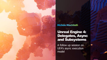
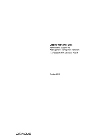
Fig. 2. Graphical notation for hierarchical modeling in AADLbetter quality system design, and decreased time-to-market for the aerospace industry. MetaH is a proven conceptand have been researched by both academia and industry for more than a decade.AADL was introduced in 2004 and revised in January 2009. The latest version, AADL V2.0, available as SAEAS5506C, was revised in August 2017 [15]. AADL has been considered by embedded system designers at Honeywell, Rockwell Collins, Lockheed Martin, the European Space Agency, Airbus and other safety-critical industries.An important collaborative System Architecture Virtual Integration (SAVI) project for designing complex distributed aerospace systems has selected AADL as its architecture description language [10]. SAVI emphasizes an“Integrate, Then Build” approach—the key concept being to verify virtual integration of architectural componentsbefore implementing their internal designs. AADL supports virtual integration through an effective mechanismfor component contract specification based on interfaces and interactions and through well defined semantics forextensive formal analysis at different architecture levels.Architectural modeling in AADL is realized through component specification of both the application softwareand the execution platform. Component Type and Implementation classifiers, corresponding to embedded systementities are instantiated and connected together to form the system architecture model. It supports textual, graphicaland XML Metadata Interchange (XMI) specification formats. Figure 2 depicts hierarchical system modeling inAADL using graphical notations.Application software may contain process, data, subprogram, thread, and thread group components. The process component represents a protected memory space shared among thread subcomponents. A data componentrepresents a type, local data subcomponent, or parameter of a subprogram, i.e., callable code. A thread abstractssequential control flow. In Figure 2, a composite systemComponent is modeled with two process components,Process1 and Process2. Two thread components Thread1 and Thread2 are the subcomponents of Process1 whilethread Thread3 is a subcomponent of Process2.The execution platform is made up of computation and communication resources, consisting of processor, memory,bus, and device components. The processor represents the hardware and software responsible for thread schedulingand execution. The memory abstraction is used for describing code and data storage entities. Devices can representeither physical entities in the external environment, or interactive system components like actuators and sensors.Physical connections between execution platform components are accomplished via a bus component.System components represent compound entities containing software, execution platform or other (sub)systemcomponents.Open Source AADL Tool Environment (OSATE) [31] is an open source platform and toolset built on Eclipse toimplement AADL for the modeling and analysis of real-time embedded systems. OSATE not only provides fullfeatures text editor and a set of analysis plug-ins, but also supports domain-specific analysis plug-in development.In order to furnish AADL for DEVS modeling and DEVS-Suite simulation, the core language must be extendedto support continuous time-critical modeling. A DEVS behavioral annex targeted for the DEVS-Suite simulator isdeveloped [2]. AADL data, structure, and behavior modeling is further detailed in the next section in relation withthe proposed AADL-DEVS framework.5
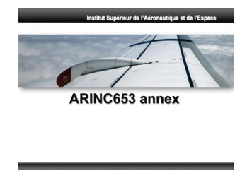
Fig. 3. AADL-DEVS Framework3.AADL-DEVS FrameworkThis framework is developed by integrating AADL, a semi-formal architecture description language, and DEVS,a formal discrete-event modeling & simulation language. The result supports both static and dynamic analysis anddesign of system architectures for safety and time-critical software-intensive system. The AADL and DEVS arespecification languages where the former can be used to define possible structural system specifications, and thelatter can be used to define combined structural and behavioral system specifications. Each of these languages ismodular and hierarchical that makes their integration simpler. The AADL provides explicit types of abstractionfor software and hardware components (i.e., nodes) and couplings (i.e., connectors). They can be used to definehybrid system specifications. The DEVS provides general-purpose components (i.e., atomic and coupled models)without the models having designated software, hardware, and hybrid.The AADL-DEVS framework has two parts – an Annex sublanguage and a code generator for DEVS modeling andsimulation. First, the AADL with its OSATE realization is extended with an Annex that conforms to the ParallelDEVS formalism and the DEVS-Suite simulator. This DEVS Annex language is specified in two parts. First, thestructural syntax of atomic and coupled DEVS models are added using the OSATE language. In other words, thestructural syntax in DEVS-Suite is mapped to that of the AADL syntax in OSATE. Second, the behavioral syntax ofthe atomic DEVS model is added using the OSATE language. The DEVS Annex structural specification accountsfor the differences between the OSATE and DEVS-Suite different primitive and compound data types with differentsyntax declarations. The data types in DEVS-Suite, unlike their counterparts in OSATE, have behavior. In addition,the DEVS Annex language is extended to support defining the behavior of atomic models (i.e., internal and externalfunctions) as basic state machines. Other functions that are added to DEVS Annex language are for the output andtime advance functions.The second part of the integration is for transforming AADL with DEVS Annex to parallel DEVS models. A codegeneration engine is developed to transform the AADL-DEVS to atomic and coupled models that can be executedin the DEVS-Suite simulator. As such, first, the AADL-DEVS models are created in OSATE, and second, themodels are automatically transformed to simulation code for the DEVS-Suite simulator. In order to generatecode for the simulator, it is also necessary to map the input and output primitive and compound data types inOSATE to their counterparts for the DEVS-Suite simulator. This has required two steps. First, looking from theDEVS-Suite language to the OSATE language, a set of generic I/O data types in the mold of the I/O data typesare defined in DEVS Annex. Second, looking from the OSATE language to the DEVS-Suite language, the codegeneration engine is extended to also transform the DEVS Annex I/O data types to their counterparts defined inthe DEVS-Suite simulator. Using the developed AADL-DEVS framework, specified parallel DEVS models can beautomatically generated, loaded, and executed in the DEVS-Suite simulator. This capability empowers the AADLstructural components to be simulatable.3.1.AADL ModelingDue to its extensive support for modeling, the AADL-DEVS framework relies on AADL for modeling capability.AADL Modeling in AADL-DEVS framework is focused on Structure, Data, and Behavior modeling based on the6
data and requirements identified in the requirement specification. Below we detail the structural and data modelingusing AADL, while behavior modeling along with the DEVS Annex is described in Section 3.2.3.1.1.Structure ModelingIn AADL, a structural model of, an embedded system is a hierarchical composition of software and hardwarecomponents. Each component declaration incorporates component type and implementation classifiers to representexternally visible characteristics and internal realization, respectively. A component type declaration defines theinterface elements and may contain Feature, Flows and Property. Feature normally contains communication ports.AADL supports Data, Event and Event Data port to transmit data, control and control and data respectively. Portcommunication is typed and directional. An in port receives data/control and an out port sends data/control whilean in out port can send and receive data. A component implementation declaration defines the internal structure interms of Subcomponents, subcomponent Connections, Subprogram call sequences, Modes, Flow implementations,and Properties. Ports of a component declared in a type declaration are connected through connections in theAADL implementation declaration.Embedded systems are the combinations of both software and hardware requi
time. Therefore, the architecture and design specifications serve complementary roles in model-based design and virtual experimentation. The Architecture Analysis & Design Language (AADL) and Discrete Event System Specification (DEVS) are proposed as complementary methods for developing, in a step-wise fashion