Transcription
ELECTRIC e3.Black Bodies and Lasers4.Generalized Luminous Flux and Related Quantities5.Photometric and Quantum Measures6.Flicker and Color Temperature7.Desirable Illumination Levels8.Principal Lamp Typesa)Introductionb)Incandescentc)Glow Discharged)Arc Discharge9.The Ordinary Incandescent Lamp10.The Ordinary Fluorescent Lamp11.The Low-Pressure Sodium-Vapor Lamp12.Considerations of Waveform and Power13.The Pipkin Page14.Glossary15.ReferencesEXPERIMENT1.Equipment List2.Flicker3.The Photometer and Its Use4.The 60-W Incandescent Lamp5.The 40-W Rapid-Start Fluorescent Lamp6.The 55-W -Low-Pressure Sodium-Vapor LampREPORTElectric Lighting - 1
Electric Lighting - 2
Electric Lighting - 3
Electric Lighting - 4
Electric Lighting - 5
Electric Lighting - 6
Electric Lighting - 7
Electric Lighting - 8
Electric Lighting - 9
Electric Lighting - 10
Electric Lighting - 11
Electric Lighting - 12
Electric Lighting - 13
Electric Lighting - 14
Electric Lighting - 15
Electric Lighting - 16
Electric Lighting - 17
Electric Lighting - 18
Electric Lighting - 19
Electric Lighting - 20
Electric Lighting - 21
Electric Lighting - 22
Electric Lighting - 23
Electric Lighting - 24
Electric Lighting - 25
Electric Lighting - 26
Electric Lighting - 27
Electric Lighting - 28
Electric Lighting - 29
Electric Lighting - 30
Electric Lighting - 31
Electric Lighting - 32
Electric Lighting - 33
Electric Lighting - 34
Electric Lighting - 35
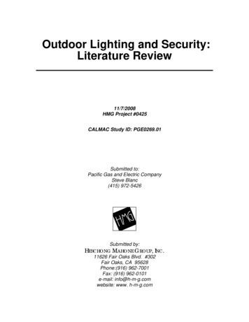
ThePipkin PagesThe legacy of Marvin Pipkin looms large in the history of electric lighting. But only forhis luminous technical achievements. About Pipkin the man we know virtually nothing§.In the early years of incandescent lamps, the bulb was of clear glass and the apparentsource of light the filament itself. This caused severe glare and eye-strain and led to thedevelopment of lampshades which, in addition to reducing glare by diffusing the light, alsoreduced the reduced the intensity of illumination.Then, about 1925, Marvin Pipkin of General Electric discovered the secret of insidefrosting light bulbs. For many years people had recognized the utility of frosting since itreduced the brilliance of the filament by a factor of roughly a hundred. And originally thefrosting was achieved either by acid etching or spraying a mineral paint onto the exteriorsurface: both methods tended to absorb rather more light than one would wish; and the acidetched surface had a tendency to collect dirt and inhibit the removal thereof. However, insideetching weakened the bulb and enhance breakage (Howell and Schroeder, 1927). The problemwas that the acid etch cut tiny sharp crevices in the glass, from which larger crevices were wontto grow when pressure was applied to the external surface (either by lowering the pressureinside the bulb or by incautious handling). Pipkin’s brilliant solution was to apply a second etchwhich rounded out the bottoms of the crevices and greatly inhibited stress-cracking of the bulb.The resultant bulb caused the apparent source of the light to expand from the filament to asphere of much reduced luminance inside the bulb; the resulting loss in efficacy was about 2%,roughly three-fold less than with outside-frosting. With this advance, GE introduced thefamiliar “standard” bulb shape in the familiar 15 , 25 , 40 , 50 , 60 , 100 sequence.Not content to rest on his laurels, Pipkin went on in 1949 to invent the Q-coat process inwhich the inside of the lamp is “smoked” with minute particles of pure silica. This resulted inonly a slight loss of efficacy ( 2%) while making the apparent source of light the surface of thebulb itself. This breakthrough is familiar to you as the Soft White light bulb.Let us now praise famous men, and our fathers that begat us. The Lord hath wrought great glory by them throughhis great power from the beginning . Leaders of the people by their counsels, and by their knowledge of learningmeet for the people, wise and eloquent are their instructions . All these were honoured in their generations, andwere the glory of their times. There be of them, that have left a name behind them, that their praises might bereported. And some there be, which have no memorial; who are perished, as though they had never been; andare become as though they had never been born; and their children after them. But these were merciful men,whose righteousness hath not been forgotten . and their glory shall not be blotted out.Ecclesiasticus 44: 1-13§If you can discover items of interest for the Pipkin Pages, please submit them to the instructor together with completebibliographical details.Electric Lighting - 36
14.Glossary and Manufacturers’ Data SheetsThere are many specialized terms associated with lighting, as can be seen by examiningthe following glossary taken from a recent Graybar catalogue. On several following pages youwill find interesting illustrations of items of interest and a Data Sheet on the photometric sensor.15.References Cited & Recent Monographs Worth Examining.Anonymous. Fluorescent Lamps. Cleveland, General Electric (undated). (GE bulletinTP-111R]Anonymous. Incandescent Lamps. Cleveland, General Electric (1980). [GE bulletinTP-11OR11Barrows, W.E. Light, Photometry, and Illuminating Engineering (3rd edn.). New York,McGraw-Hill (1951).Elenbaas, W. Light Sources. New York, Crane, Russak & Company (1972).Gaster, L. and Dow. J.S. Modern Illuminants and Illuminating Engineering. London,Whittaker (1915).Howell, J.W. History of the Incandescent Lamp. Schenectady, NY, Maqua Company (1927).Nuckolls, J.L. Interior Lighting for Environmental Designers. New York, John Wiley & Sons(1976).Rupert, C.S. and Latarjet, R. Toward a nomenclature and dosimetric scheme applicable to allradiations. Photochem. Photobiol. 28, 3-5 (1978).Sears, F.W. Optics (3rd edn.). Cambridge, Addison-Wesley (1949).Shibles, R. Committee report: Terminology pertaining to photosynthesis. Crop Sci. 16,437-439 (1976).Wright, W.D. The Measurement of Colour (4th edn.). New York, Van Nostrand Reinhold(1969).MONOGRAPHSCayless, M. A. and Marsden, A. M. Lamps and Lighting. Baltimore ,Edward Arnold (1983).Helms, R. N. and Belcher, M. C. Lighting for Energy-Efficient Luminous Environments.Englewood Cliffs, NJ, Prentice-Hall(1991).Murdoch, J. B. Illumination Engineering, From Edson's Lamp to the Laser. New York,Macmillan (1985).Nuckolls, J. L. Interior Lighting for Environmental Designers. New York, Johw Wiley & Sons(1983).Electric Lighting - 37
Electric Lighting - 38
Electric Lighting - 39
Electric Lighting - 40
Electric Lighting - 41
Electric Lighting - 42
Electric Lighting - 43
Electric Lighting - 44
B.EXPERIMENT1.Equipment List1relay rack containing the usual test equipment1Electrical Energy Monitor chassis1stroboscopic light source (1 group at a time)1single-phase wattmeter1variable autotransformer1quantum/radiometer/photometer (Li-Cor model Li-189)1incandescent lamp test fixture160-W soft-white incandescent lamp160-W compact fluorescent lamp140-W warm-white rapid-start fluorescent lamp GE model F40WW-R5-WM1LED lamp1LED based “fluorescent” tube lamp155-W low-pressure sodium-vapor lamp mounted in a test fixtureSuch other equipment as may prove useful2.FlickerWARNING: Studentswithknown or suspected epileptictendencies must omit theflicker experiments.Step into the equipment storage room where the lab's only stroboscope has beenset up #. Fiddle with the unit until you learn how it operates. Then turn off the room lightsand adjust the flash frequency until the flicker ceases to be noticeable. Make a note ofthis frequency, converting the rpm readout to frequency in Hertz.#Obviously, since there is only one such device, not all groups can do this portion of the experiment first.Take turns!Electric Lighting - 45
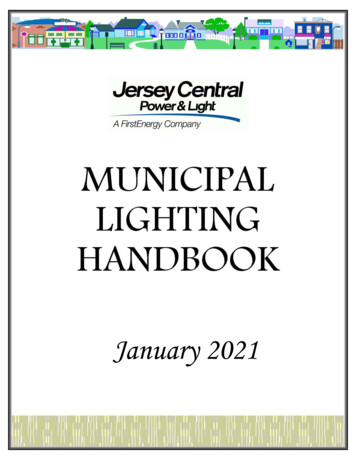
3.The Photometer and Its UseThe photometers are durable, but still use care with this instrument. Attach aphotometric head to the Li-189, and calibrate as follows: keep sensor cover on, turn on,press CAL, select klux units, and then adjust screw until the reading matches the valueon the tag. Then press CAL to exit the calibration mode and record ambient light.4.The 60-W Incandescent LampThe 60-W incandescent lamp comes mounted in a test fixture whose blockdiagram is given in Fig. 7.5A. The overall experimental arrangement is shown in Fig.7.5B. Fig. 7.6 shows a small chassis the Electrical Energy Monitor (EEM) that is usefulfor interconnecting various meters and parts.(a)Measure the low-voltage dc resistance of the lamp when its filament is atroom temperature.(b)For this part only, employ 120 VDC rather than AC via the variac(replace AC cord and variac with DC cord). Using your well-honedexperimental arts, capture and print out the inrush current.(c)Attach the wattmeter to measure power absorbed by the lamp. Set thelamp voltage to 120 VAC. Measure and record the lamp current and themeasured power and make a copy of the current waveform.(d)Simultaneously display and then capture the lamp voltage and currentwaveforms at 120 VAC using CH1 (using a 10X scope probe attached tothe “Voltage” node on the EEM) and CH2 (using the Hall Effect current tovoltage probe with multiple turns of banana lead wrapped around its claw)of the scope and the FFT of the current. Measure any observable phaseshift between the two waveforms.(e)Measure, as a function of AC lamp voltage, the lamp's current, wattage,and luminance. Cover the range of 0-120 VAC.5.The 60-W Compact Fluorescent LampRepeat (c), (d), and (e) above using the 60-W compact fluorescent lamp.6.The LED LampRepeat (c), (d), and (e) above using the LED lamp.Electric Lighting - 46
Electric Lighting - 47
Electric Lighting - 48
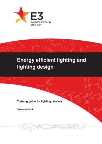
Because we have only two low-pressure sodium-vapor lamps and two LED lamps, the firsttwo lab groups to complete Part 4 should tackle Part 8 before Part 5. As a group finishesPart 8 it should hand off its luminaire to the next lab group to finish either Part 4 or Part 5.Because the output from the sodium lamp can seem dazzling, take care to set theluminaire on its edge so that it faces and illuminates only the wall behind the labbench.7.The 40-W Rapid-Start Fluorescent LampThe 40-W fluorescent lamp comes mounted in a test fixture whose block diagramis given in Fig. 7.7. The overall experimental arrangement is akin to Fig. 7.5B. Thedetails of measurement are similar to those for the incandescent lamp.(a)Set the luminaire voltage driving the ballast to 120 VAC; andsimultaneously display and then copy the voltage and current waveformsand the FFT of the current waveform. Measure observable phase shift.(b)Over the luminaire voltage range 100-125 V, measure system wattage,rms current, and luminance as a function of voltage.(c)Replace the 40-W Fluorescent lamp with the LED based tube lamp andrepeat a and b above.8.The 55-W Low-Pressure Sodium-Vapor LampThis lamp, together with its ballast comes mounted in a luminaire to which a cordwith a three-prong plug is attached. Connect it to the wall by way of the arrangementshown in Fig. 7.5B.(a)Set the luminaire voltage to 120 V and simultaneously display and thencopy the voltage and current waveforms and the FFT of the currentwaveform. Measure observable phase shift.(b)Over the luminaire voltage range 90-120 V, obtain system voltage, systemwattage, rms current, and luminance as a function of voltage. Beware ofdevice hysteresis # !In particular, do not momentarily turn off the luminaire because it won't restart until it has cooled down! Notealso that, by long standing tradition, at least one group always falls into this trap: Just don’t let it be you.Electric Lighting - 49#
Electric Lighting - 50
C.Report(a) FlickerAt what frequency in Hertz did flicker cease to be annoying to you? Whatdoes this imply about the design of an AC power system for lighting use?For that matter, what does it imply about the refresh rate that you employfor your TV or PC Monitor?(b)The 60-W incandescent lamp.(i) Provide a hardcopy of the inrush current. Comment cogently. At alamp voltage of 120 V, what are the voltage drops at the neutralreturn and across the 1.00-Ω resistor? Comment as to theirmagnitude compared to lamp voltage.(ii) Present the hardcopy of the lamp voltage and current waveforms andthe FFT of the current at 120 VAC. What is the observed phase shiftbetween the two waveforms? And approximate power factor?(iii) Tabulate lamp voltage, current, wattage and luminance. Normalize(e.g. use 120VAC values as base) the current, wattage, andluminance relative to their values at 120VAC and include thesenormalized values in the table.(iv) On the same graph sheet, plot (as a function of lamp voltage) lampcurrent, system wattage, and luminance (each normalized relative toits value at 120 V) . Comment cogently.(v) On a separate graph sheet, plot system wattage versus the product(rms lamp voltage) x (rms lamp current). Comment cogently.Present in suitable fashion a comparison of the power factors derivedin this graph. Comment cogently.(vi) From your measurements, calculate the inferred filament temperatureversus lamp voltage. Be very explicit about how you do this. Nowtabulate this data and plot filament temperature versus voltage.Comment cogently on this result. This process of plotting relative values is known as ‘normalization’.Electric Lighting - 51
(c)For both the 40-W fluorescent and LED tube lamps.(i) Present the hardcopy of the lamp voltage and current waveforms andthe FFT of the current at 120 VAC. Determine the approximatepower factor and comment.(ii) Tabulate lamp voltage, current, wattage and luminance. Normalizethe current, wattage, and luminance relative to their values at120VAC and plot versus voltage on the same graph sheet.Comment.(iii) On a separate graph sheet, plot system wattage versus the product(rms ballast voltage) x (rms system current). Comment cogently. Inparticular, what (if anything) do these data tell you about systempower factor?(d)For the 60-W Compact Fluorescent AND LED Lamps(i) Present the hardcopy of the lamp voltage and current waveforms andthe FFT of the current at 120 VAC. Determine the approximatepower factor and comment.(ii) Tabulate lamp voltage, current, wattage and luminance. Normalizethe current, wattage, and luminance relative to their values at120VAC and plot versus voltage on the same graph sheet.Comment.(iii) On a separate graph sheet, plot system wattage versus the product(rms ballast voltage) x (rms system current). Comment cogently. Inparticular, what (if anything) do these data tell you about systempower factor?(e)Discuss the following issues for the sodium vapor lamp.(i) Present the hardcopy of the lamp voltage and current waveforms andthe FFT of the current at 120 VAC. Determine the approximatepower factor and comment.(ii) Tabulate lamp voltage, current, wattage and luminance. Normalizethe current, wattage, and luminance relative to their values at120VAC and plot versus voltage on the same graph sheet.Comment.Electric Lighting - 52
(iii) On a separate graph sheet, plot system wattage versus the product(rms ballast voltage) x (rms system current). Comment cogently. Inparticular, what (if anything) do these data tell you about systempower factor?Electric Lighting - 53
Electric Lighting - 37 14. Glossary and Manufacturers’ Data Sheets There are many specialized terms associated with lighting, as can be seen by examining the following glossary taken from a recent Graybar catalogue. On several following pages you will find interesting illustrations of