Transcription
UL924EMERGENCY LIGHTING Relays forBYPASS/SHUNT & Automatic loadcontrol applicationsL I GHT IN G CO N T RO L SOur UL924 Emergency Lighting Automatic Load ControlRelays are designed for applications that require anemergency load to be switched on during a loss of normalpower. These economically priced relays are availableprepackaged in their own NEMA 1 enclosure.
Functional Devices LightingTable of ContentsUL924 Emergency Lighting Automatic Load Control 14ESRBE277C15ESRTB16UL924 Emergency Lighting Bypass/Shunt R01P22ESR02P23
UL924 Emergency Lighting Automatic Load Control RelaysQuick Reference ChartCoil VoltageFDIModel BAC Test ProceduresElectronic Local TestContacts MagneticBallastBallastButton120-277SPST20 A16 A120-277SPST20A16 A120-277SPST5A5A120-277SPST5A5A120-277SPST10 A10 A120SPST10 A2A277SPST10 A2A UL924; Emergency Lighting SelfTest FireBallast NippleRemote Dimmer AlarmTestOverride Test ChannelMount Mount * * * Includes Form C contact dimmer overrideModel ESRB & ESRNEnclosed Relay 10 Amp & 20 Amp SPST Automatic Load Control Relay with 120-277 Vac Coil InputFeaturesPerfect for emergency lighting automatic load control applications. Automatic load control overrideNormal control of emergency lightingCoil input range: 120 Vac through 277 VacLED indicators for normal voltage, emergency voltage, and load status10 Amp and 20 Amp SPST magnetic ballast and tungsten ratingsLED rating - Up to 16 Amp electronic ballast rating0-10 Vdc dimmer overrideRemote control/test capability (model ESRTB)Nipple mount, wall mount, or ballast channel mountMade in the ontrols (800) 888-55383
UL924 Emergency Lighting Automatic Load Control RelaysApplicationsBy using our Automatic Load Control Relays, you are able to complete your emergencylighting applications. High contact ratings allow for multiple loads on a single relay unit. Emergency lighting can be controlled under normal conditions using the switch input. Under normal operation, emergency light can be controlled by a controller using the drycontact input. The dry contact output can be used to override 0-10 V dimmers to full brightness(or for feedback to controllers, etc.) The on-board local test button and LEDs allow for installation to be tested immediately. A two second self-test of the unit is performed every time the wall switch input is turned off. Remote test capability allows for a button, switch, controller, fire alarm panel, etc. to beconveniently mounted anywhere desired. [Class 2 acceptable]See model ESRTB (remote test button). See page 14 for ESRTB. Different housings allow for wall or nipple mount (model ESRN), or ballast channelmount (model ESRB).Input and Output CharacteristicsElectrical Specifications (ESRB, ESRN)Quick Reference ChartHousing:Normal Power Supply VoltageNormal Power Current DrawNormal Power Operating Frequency120-277Vac24mA max50/60HzEmergency Power Supply VoltageEmergency Power Current DrawEmergency Power Operating Frequency120-277Vac118mA max50/60HzRemote Test Input (Class 2, Dry Contact)ESRTB or other switching method ¹,²Feedback/Dimmer ContactSwitching Capability (Dry Contact Output)130mA @ 250V maxRelay Contact (ESRN)SPST20A Magnetic Ballast @ 277V16A Electronic Ballast @ 277V10A Tungsten @ 120VRelay Contact (ESRB)SPST10A Magnetic Ballast @ 277V10A Electronic Ballast @ 277V10A Tungsten @ 120V1: If not using the ESRTB Remote Test Button (sold separately), switchingmethods should be rated for at least 24Vdc. External voltage should not besupplied to this input. No specific current rating is required.2: To maintain Class 2, a maximum of 45 total test inputs (ESRB and/orESRN) can be wired in parallel per ESRTB.4Functional Devices, Inc.Mechanical Specifications Lighting Control ProductsWire:Operating Temperature:Humidity Range:Approvals:UL Acceptedfor use in Plenum, NEMA 116” 600V Rated-30 to 140 F (-35 to 60 C)5 to 95% (noncondensing)Rated for dry and damplocations onlyUL Listed, UL924, C-ULCE, RoHS
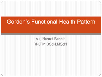
UL924 Emergency Lighting Automatic Load Control RelaysWiring DescriptionsWire ColorDescriptionNotesBLACKNormal HotCan be different voltage than Emergency.WHITE/BLACKSwitch Input (Self-Test Input)WHITE/BLACK wires must be from samebranch circuit as BLACK and RED. Whenswitched off, a two second delay keeps theload on to test emergency power. This doesnot test feedback/dimmer output.REDNormal Neutral or other PhaseCan be different voltage than Emergency.BROWNEmergency Hot–BLUEEmergency Hot Switched to LoadYELLOWEmergency Neutral or other PhaseWHITE/BLUE (ESRB)Terminal Screw 4 (ESRN)WHITE/RED (ESRB)Terminal Screw 3 (ESRN)Remote Test Input (Class 2, DryContact Input)Switches out the voltage from BROWN–When wiring multiple units together, WHITE/BLUEor Terminal Screw 4 must be a shared common.Test is performed when Input is CLOSED.Feedback/Dimmer ContactVIOLETS (ESRB)(Dry Contact Output)Terminal Screws 1, 2 (ESRN)Switch Input does not test this output.Output is OPEN when normal power is absent orRemote Test Input is CLOSED.Output is CLOSED when normal power is presentand Remote Test Input is OPEN.Wiring InformationESRNLoad Power LEDLocal Test ButtonEmergency Power LEDNormal Power LEDRemote Test Input(Dry Contact Input) Feedback/Dimmer Contact(Dry Contact Output) ** Can be used to override 0-10V dimmer tofull brightness by breaking the positive ( )leg or monitor status of Normal Power.130mA @ 250V max.EmergencyPower123 Class 2 input that can be tied to a remotebutton/switch (N/O) or to a controller.4Remote Test Button (Model ESRTB)sold V#White/BlackEmergencyLoadBlue120277V# Optional switch or controller to controlEmergency Load under normal conditions andperform self-test. Cap off White/Black if not usedwww.functionaldevices.com/lighting-controls (800) 888-55385
UL924 Emergency Lighting Automatic Load Control RelaysESRB# Optional switch or controller tocontrol Emergency Load under normalconditions and perform self-test.Cap off White/Black if not usedRemote Test Input(Dry Contact Input) Local Test ButtonNormal Power LED Class 2 input that can be tied toremote button/switch (N/O) orto a controllerRemote Test Button (Model ESRTB)Sold Seperately#Emergency Power LEDLoad Power LED* Can be used to override 0-10Vdimmer to full brightness bybreaking the positive ( ) leg ormonitor status of Normal Power130mA @ 250V eedback/Dimmer Contact(Dry Contact Output)*120 277V120 277VEmergencyEmergencyPowerLoadESRN & ESRB ESRNI.D. 0.204”0.50” NPT1.81”1.325.50”6Functional Devices, Inc.1.275 ” Lighting Control Products
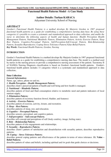
UL924 Emergency Lighting Automatic Load Control RelaysTypical ApplicationsUsing Emergency Lighting as Normal Lighting (ESRN & atoror InverterHotEmergencyBreakerGeneratoror InverterNeutralEmergencyNeutralNormal /Emergency LightingBlueBrownYRYellowNormalPanelUtilityHot* White/BlackWallSwitchControlCircuitryViolet or Terminal 2Normal PowerFeedback Status(Dry Contact Output)BlackNormalBreakerWhite/Red or Terminal 3GRedUtilityNeutralViolet or Terminal 1White/Blue or Terminal 4NormalNeutral Class 2 Remote Test Input (N/O) forbutton, controller, or fire alarm panel* The White/Black wire must be onthe same branch circuit as theBlack wire.Normal LightingTo use Remote Test Input, theWhite/Black wire must be de-energized.Input can also be sent by a controller.Remote Test Button (Model ESRTB)sold separatelyWhen not using the Remote Test Input,cap off the White/Red and White/Bluewires individually (if present).Overriding a 0-10Vdc Dimmer (ESRN & ESRB)AutomaticTransferSwitchGeneratoror InverterHotGeneratoror ilityNeutralEmergencyNeutralControlCircuitryViolet or Terminal 1Violet or Terminal 2BlackNormalBreakerWhite/Red or Terminal 3GRed* White/BlackNormalLighting Class 2 Remote Test Input (N/O) forbutton, controller, or fire alarm panelRemote Test Button (Model ESRTB)sold separately White/Blue or Terminal 4NormalNeutral* The White/Black wire must be onthe same branch circuit as theBlack wire.To use Remote Test Input, theWhite/Black wire must be de-energized.Input can also be sent by a controller.When not using the RemoteTest Input, cap off the White/Red and White/Blue wiresindividually (if ency LightingBlueBrownHN0-10VDimmerControl -www.functionaldevices.com/lighting-controls (800) 888-55387
UL924 Emergency Lighting Automatic Load Control RelaysTesting and TroubleshootingTest Procedure: Four Options to Test the ESRB and ESRN After Installation:Initial Test for Correct WiringApply Emergency Power to the Emergency Power Input and Normal Power to the Normal Power Input. (If using theWall Switch Input, apply Normal Power to the switch also, but keep the switch OFF/OPEN.)a. The Red LED (Emergency Power available) should be ON.b. The Green LED (Normal Power available) should be ON.c. The Yellow LED (Load Status) should be OFF.d. The Load should be OFF.e. The Feedback/Dimmer Contact should be CLOSED.Local Test Button1. Turn switched circuit OFF. Emergency light should be OFF.2. Press and hold “Local Test Button”3. Emergency light should turn ON.4. Release “Local Test Button” and emergency light should turn OFF.Remote Test Button (Model ESRTB - sold separately)1. Turn switched circuit OFF. Emergency light should be OFF.2. Press and hold “Remote Test Button”3. Emergency light should turn ON.4. Release “Remote Test Button” and emergency light should turn OFF.Wall Switch or Controller Contact1. Turn ON switch if not already on.2. Emergency light should turn ON.3. Turn wall switch OFF.4. Emergency light will remain on for two seconds before turning OFF.To test the ESRB and ESRN periodically, repeat the appropriate Test Procedure above in accordance withnational and local codes.TroubleshootingConditionActionRed LED is OFFCheck Emergency Power Input wiring (BROWN and YELLOW wires) and voltage.Green LED is OFFCheck Normal Power Input wiring (BLACK and RED wires) and voltage.Yellow LED is ONbut Load is OFF Load is ON butYellow LED is OFFReplace unit.Yellow LED andLoad do not turn onwhen being tested Yellow LED andLoad will not turn OFF Verify status of Normal Power Input. Open Wall Switch Input. Verify that no test inputs are stuck closed. (i.e. Remote Test Input is not closed).8Functional Devices, Inc. Check Load wiring (BLUE wire and Load’s neutral).Verify Load’s operating voltage is the same as the Emergency Power Input Voltage.Check bulbs and ballast.Replace unit.Check bulbs and ballast.Check wiring connections if using a remote test option.Press local test button on the unit.Replace unit.Lighting Control Products
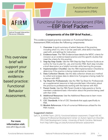
UL924 Emergency Lighting Automatic Load Control RelaysModel ESRN-1Enclosed Relay 20 Amp SPST Automatic Load Control RelayLocal Test ButtonLoad Power LED (Yellow)Emergency Power LED (Red)Normal Power LEDRemote Test Input(Dry Contact Input) 3 Class 2 input that can be tied toa remote button/switch (N/O) orto a controller.4Remote Test Button (ModelESRTB) sold separatelyESRN-1EmergencyPowerBrown (Hot)NormalPowerRedYellowBlack (Hot)120277V120277V#White/BlackEmergencyLoadBlue# Optional switch or controller to controlEmergency Load under normal conditionsand perform self-test. Cap off White/Blackif not used.Specifications# Relays & Contact Type:Expected Relay Life:Operating Temperature:Operate Time:LED:Dimensions:Wires:Approvals:Housing Rating:Gold Flash:Override (Test Switch):Humidity Range:Test and TroubleshootingOne (1) SPST Continuous Duty Coil10 million cycles minimum mechanical-30 to 140 F18msGreen Normal PowerRed Emergency PowerYellow Load Power4.0 x 4.57 x 1.80 with .50 NPT Nipple16 , 600V RatedUL Listed, UL924, C-UL, CE, RoHSUL Accepted for Use in Plenum, NEMA 1NoNo5-95%(noncondensing)Bypass/Shunt Relay ApplicationCoil Current:Normal Power 24 mA maxEmergency Power 118 mA maxCoil Voltage Input:Emergency Input: 120-277 Vac(50/60 Hz)Normal Input: 120-277 Vac(50/60 Hz)Using Emergency Lighting as Normal LightingGeneratoror InverterHotGeneratoror InverterNeutralUtilityNeutralWall Switch or Controller Contact1. Turn ON switch if not already on.2. Emergency light should turn ON.3. Turn wall switch OFF.4. Release “Local Test Button” or “Remote Test Button” andemergency light should turn OFF.ESRN-1EmergencyPanelEmergencyBreakerNormal /Emergency elUtilityHotOPEN.)a. The Red LED (Emergency Power available) should be ON.b. The Green LED (Normal Power available) should be ON.c. The Yellow LED (Load Status) should be OFF.d. The Load should be OFF.Contact Ratings:20 Amp Magnetic Ballast @ 277 VacTest Button16 Amp Electronic Ballast @ 277 Vac1. Turn switched circuit OFF. Emergency light should be OFF.10 Amp Tungsten @ 120 Vac2. Press and hold “Local Test Button” or “Remote Test Button”3. Emergency light should turn ON.4. Release “Local Test Button” and emergency light should turnOFF.Our Bypass/Shunt Relays are UL924 Listed and suitable for shunting around wallswitches and/or lighting control panel circuits, in order to turn on emergency lightingwhen normal utility power is lost.AutomaticTransferSwitchInitial TestApply Emergency Power to the Emergency Power Input and NormalPower to the Normal Power Input. (If using the Wall Switch Input,apply Normal Power to the switch also, but keep the switch OFF/* al* The White/Black wire must be onthe same branch circuit as theBlack wire.To use Remote Test Input, theWhite/Black wire must be de-energized.Input can also be sent by a controller.ControlCircuitryGRedTerminal 3 Terminal 4 Class 2 Fire AlarmInterface, Remote Test Input (N/O)Normal Lighting for Button or ControllerRemote Test Button (Model ESRTB)sold ols (800) 888-55389
UL924 Emergency Lighting Automatic Load Control RelaysModel ESRLBCEnclosed Relay 5 Amp SPST Automatic Load Control Relay with 120-277 Vac Coil Input# Optional wall switch or controller tocontrol Emergency Load under normalconditions and perform self-test.Cap off Wht/Blk if not used.Remote Test Input(Dry Contact Input) 120 277VLocal Test Button Class 2 input that can be tied toremote button/switch (N/O) orto a controller.#NormalPowerEmergency Power LEDRemote Test Button (Model ESRTB)sold ESRLBCFeedback/Dimmer Contact(Form C Dry Contact Output)** Can be used to override 0-10Vdimmer to full brightness bybreaking the positive ( ) leg ormonitor status of Normal Power.1A @ 30 Vdc.Load Power LEDNormal Power LEDWht/BlkBlackRedBrownYellowBlue120 ngInitial Test for Correct WiringApply Emergency Power to the Emergency Power Input and Normal Powerto the Normal Power Input. (If using the Wall Switch Input [Wht/Blk wire],apply Normal Power to the switch also, but keep the switch OFF/OPEN.)Coil Voltage Input:a. The Red LED (Emergency Power available) should be ON.Emergency Input: 120-277 Vacb. The Green LED (Normal Power available) should be ON.(50/60 Hz)Normal Input: 120-277 Vacc. The Yellow LED (Load Status) should be OFF.Dimensions:(50/60 Hz)d. The Load should be OFF.Wires:e. The N/O Feedback/Dimmer Contact should be CLOSED.Relay Contact Ratings:Approvals:5 Amp Electronic/LED Ballast @ 277 Vac Local Test ButtonHousing Rating:1. Turn wall switch OFF. Emergency light should be OFF.5 Amp Ballast @ 120-277 VacGold Flash:Feedback/Dimmer Override Contact: 2. Press and hold “Local Test Button”Override (Test Switch):3. Emergency light should turn ON.1Amp Resistive @ 30 VdcHumidity Range:4. Release “Local Test Button” and emergency light should turn OFF.Remote Test Button (Model ESRTB - sold separately)1. Turn wall switch OFF. Emergency light should be OFF.2. Press and hold “Remote Test Button”3. Emergency light should turn ON.Our Bypass/Shunt Relays are UL924 Listed and suitable for shunting around wall switches4. Release “Remote Test Button” and emergency light should turn OFF.and/or lighting control panel circuits, in order to turn on emergency lighting whenWall Switch or Controller Contactnormal utility power is lost.1. Turn ON switch if not already on.2. Emergency light should turn ON.3. Turn wall switch OFF.4. Emergency light will remain on for two seconds before turning OFF.# Relays & Contact Type:Expected Relay Life:Operating Temperature:Operate Time:LED:One (1) SPST Continuous Duty Coil10 million cycles minimum mechanical-30 to 140 F18msGreen Normal PowerRed Emergency PowerYellow Load Power5.63 x 1.40 x 1.00 16 , 600V RatedUL Listed, UL924, C-UL, CE, RoHSUL Accepted for Use in Plenum, NEMA 1NoNo5-95%(noncondensing)Coil Current:Normal Power 24 mA maxEmergency Power 88 mA maxBypass/Shunt Relays & Dimming Override ApplicationTroubleshootingConditionActionRed LED is OFFCheck Emergency Power Input wiring (BROWN and YELLOW wires) and voltage.Green LED is OFFCheck Normal Power Input wiring (BLACK and RED wires) and voltage.Yellow LED is ONbut Load is OFF Load is ON butYellow LED is OFFReplace unit.Yellow LED andLoad do not turn onwhen being tested Yellow LED andLoad will not turn OFF Verify status of Normal Power Input. Open Wall Switch Input. Verify that no test inputs are stuck closed. (i.e. Remote Test Input is not closed).10Functional Devices, Inc.Check Load wiring (BLUE wire and Load’s neutral).Verify Load’s operating voltage is the same as the Emergency Power Input Voltage.Check bulbs and ballast.Replace unit.Check bulbs and ballast.Check wiring connections if using a remote test option.Press local test button on the unit.Replace unit. Lighting Control Products
UL924 Emergency Lighting Automatic Load Control RelaysTypical ApplicationsUsing Emergency Lighting as Normal Lighting lGeneratoror InverterHotNormal /Emergency or nelUtilityHot* BreakerNormal PowerFeedback Status(Dry Contact trolCircuitry White/Blue Class 2 Remote Test Input (N/O) forbutton, controller, or fire alarm panel* The White/Black wire must be onthe same branch circuit as theBlack wire.Normal LightingTo use Remote Test Input, theWhite/Black wire must be de-energized.Input can also be sent by a controller.Remote Test Button (Model ESRTB)sold separatelyWhen not using the Remote Test Input,cap off the White/Red and White/Bluewires individually (if present).Overriding a 0-10Vdc Dimmer lEmergencyBreakerGeneratoror lBreakerWhite/RedGRed* White/BlackNormalLighting Class 2 Remote Test Input (N/O) forbutton, controller, or fire alarm panelRemote Test Button (Model ESRTB)sold separately White/BlueNormalNeutral* The White/Black wire must be onthe same branch circuit as theBlack wire.To use Remote Test Input, theWhite/Black wire must be de-energized.Input can also be sent by a controller.When not using the RemoteTest Input, cap off the White/Red and White/Blue wiresindividually (if ency LightingBlueBrownGeneratoror InverterHotHN0-10VDimmerControl -www.functionaldevices.com/lighting-controls (800) 888-553811
UL924 Emergency Lighting Automatic Load Control RelaysModel ESRLBCNDEnclosed Relay 5 Amp SPST Automatic Load Control Relay with 120-277 Vac Coil Input- No Delay# Optional wall switch or controller tocontrol Emergency Load under normalconditions. Cap off Wht/Blk if not used.Remote Test Input(Dry Contact Input) 120 277VLocal Test Button Class 2 input that can be tied toremote button/switch (N/O) orto a controller.#NormalPowerEmergency Power LEDRemote Test Button (Model ESRTB)sold ESRLBCNDFeedback/Dimmer Contact(Form C Dry Contact Output)** Can be used to override 0-10Vdimmer to full brightness bybreaking the positive ( ) leg ormonitor status of Normal Power.1A @ 30 Vdc.Load Power LEDNormal Power LEDWht/BlkBlackRedBrownYellowBlue120 ngInitial Test for Correct WiringApply Emergency Power to the Emergency Power Input and Normal Powerto the Normal Power Input. (If using the Wall Switch Input [Wht/Blk wire],apply Normal Power to the switch also, but keep the switch OFF/OPEN.)Coil Voltage Input:a. The Red LED (Emergency Power available) should be ON.Emergency Input: 120-277 Vacb. The Green LED (Normal Power available) should be ON.(50/60 Hz)Normal Input: 120-277 Vacc. The Yellow LED (Load Status) should be OFF.Dimensions:(50/60 Hz)d. The Load should be OFF.Wires:e. The N/O Feedback/Dimmer Contact should be CLOSED.Relay Contact Ratings:Approvals:5 Amp Electronic/LED Ballast @ 277 Vac Local Test ButtonHousing Rating:1. Turn wall switch OFF. Emergency light should be OFF.5 Amp Ballast @ 120-277 VacGold Flash:Feedback/Dimmer Override Contact: 2. Press and hold “Local Test Button”Override (Test Switch):3. Emergency light should turn ON.1Amp Resistive @ 30 VdcHumidity Range:4. Release “Local Test Button” and emergency light should turn OFF.Remote Test Button (Model ESRTB - sold separately)1. Turn wall switch OFF. Emergency light should be OFF.2. Press and hold “Remote Test Button”3. Emergency light should turn ON.Our Bypass/Shunt Relays are UL924 Listed and suitable for shunting around wall switches4. Release “Remote Test Button” and emergency light should turn OFF.# Relays & Contact Type:Expected Relay Life:Operating Temperature:Operate Time:LED:One (1) SPST Continuous Duty Coil10 million cycles minimum mechanical-30 to 140 F18msGreen Normal PowerRed Emergency PowerYellow Load Power5.63 x 1.40 x 1.00 16 , 600V RatedUL Listed, UL924, C-UL, CE, RoHSUL Accepted for Use in Plenum, NEMA 1NoNo5-95%(noncondensing)Coil Current:Normal Power 38 mA maxEmergency Power 88 mA maxBypass/Shunt Relays & Dimming Override Applicationand/or lighting control panel circuits, in order to turn on emergency lighting whennormal utility power is lost.TroubleshootingConditionActionRed LED is OFFCheck Emergency Power Input wiring (BROWN and YELLOW wires) and voltage.Green LED is OFFCheck Normal Power Input wiring (BLACK and RED wires) and voltage.Yellow LED is ONbut Load is OFF Load is ON butYellow LED is OFFReplace unit.Yellow LED andLoad do not turn onwhen being tested Yellow LED andLoad will not turn OFF Verify status of Normal Power Input. Open Wall Switch Input. Verify that no test inputs are stuck closed. (i.e. Remote Test Input is not closed).12Functional Devices, Inc.Check Load wiring (BLUE wire and Load’s neutral).Verify Load’s operating voltage is the same as the Emergency Power Input Voltage.Check bulbs and ballast.Replace unit.Check bulbs and ballast.Check wiring connections if using a remote test option.Press local test button on the unit.Replace unit. Lighting Control Products
UL924 Emergency Lighting Automatic Load Control RelaysTypical ApplicationsUsing Emergency Lighting as Normal Lighting nelGeneratoror InverterHotBlueBrownEmergencyBreakerNormal /Emergency LightingYRYellowGeneratoror nelUtilityHot* BreakerNormal PowerFeedback Status(Dry Contact trolCircuitry White/Blue Class 2 Remote Test Input (N/O) forbutton, controller, or fire alarm panel* The White/Black wire must be onthe same branch circuit as theBlack wire.Normal LightingTo use Remote Test Input, theWhite/Black wire must be de-energized.Input can also be sent by a controller.Remote Test Button (Model ESRTB)sold separatelyWhen not using the Remote Test Input,cap off the White/Red and White/Bluewires individually (if present).Overriding a 0-10Vdc Dimmer nelEmergencyBreakerGeneratoror /BrownControlCircuitryViolet orWhite/VioletBlackNormalBreakerWhite/RedGRed* White/BlackNormalLighting Class 2 Remote Test Input (N/O) forbutton, controller, or fire alarm panelRemote Test Button (Model ESRTB)sold separately White/BlueNormalNeutral* The White/Black wire must be onthe same branch circuit as theBlack wire.To use Remote Test Input, theWhite/Black wire must be de-energized.Input can also be sent by a controller.When not using the RemoteTest Input, cap off the White/Red and White/Blue wiresindividually (if ency LightingBlueBrownGeneratoror InverterHotHN0-10VDimmerControl -www.functionaldevices.com/lighting-controls (800) 888-553813
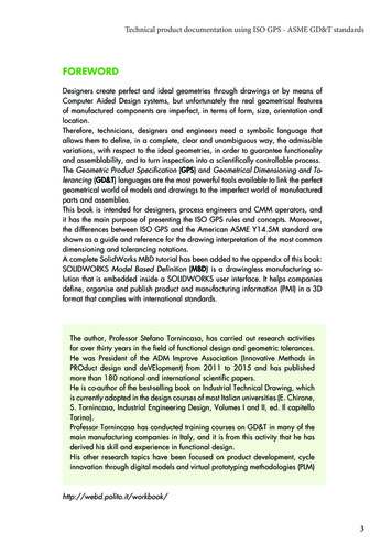
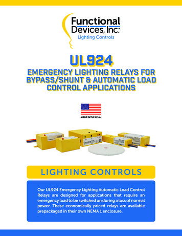
l ESRBE01CEnclosed Relay 10 Amp SPST-NC with 120 Vac Coil and Switched Utility DetectionBlkUtility 120 VacBluEmergency Hotto LoadPrpSwitched Utility120 VacYelEmergency HotWhtUtility NeutralGryEmergency Neutral Ballast Size HousingSpecifications# Relays & Contact Type:Expected Relay Life:Operating Temperature:Operate Time:Relay Status:Emergency Power Present:Dimensions:Wires:Approvals:Gold Flash:One (1) SPST-NC Continuous Duty Coil10 million cycles minimum mechanical-30 to 140 F50 msRed LED On ActivatedYellow LED On Transfer Power Present4.60 x 1.20 x 1.70 16.00 , 600V RatedUL Listed, UL924, C-UL, CE, RoHSNoContact Ratings:10 Amp Magnetic Ballast @ 277 Vac (N/C)2 Amp Electronic Ballast @ 120 Vac (N/C)Coil Current:100 mA @ 120 VacNotes: Control input on purple wire detects wall switch,allowing emergency light to be used as normallighting. Smaller design to fit inside ballast housing offluorescent light fixture.Coil Voltage Input:120 Vac ; 50-60 HzInitial Wiring VerificationField Inspection1. Turn OFF Normal Power, Transfer Power, and Wall Switch.1. Ensure Normal Power and Transfer Power are energized.2. Wire relay according to wiring diagram.2. Turn OFF Wall Switch. Light will turn OFF.3. Energize Transfer Power. Emergency Light should illuminate.3. Red LED and Yellow LED will be illuminated.4. Energize Normal Power. Emergency Light will turn OFF.4. Turn OFF Normal Power. Red LED will turn OFF. Emergency Light will illuminate.5. Turn ON Wall Switch. Emergency Light should illuminate.Use of Normal Light as Emergency LightOur Emergency Bypass / Shunt Relays are UL924 Listed andsuitable for shunting around wall switches in order to turn onemergency lighting in the event of loss of normal utility power.When the Emergency Light is needed as a Normal Light as well,this application can be applied using this specific relay.When Normal Power is present, the ESR relay coil is activatedand the emergency panel is fed from Normal Power. The lightingload can be switched on/off using the existing wall switch.AutomaticTransferSwitchGeneratoror InverterHotGeneratoror InverterNeutralUtilityHotUtilityNeutralFunctional Devices, Inc. Lighting Control ProductsESRNormal /Emergency tralNormalPanelWhen Normal Power drops out, the ESR coil is deactivated andN/C contact falls closed. The Automatic Transfer Switch changesover to backup (generator) power, and the Emergency Lightremains illuminated, regardless of the position of the existingwall switch, while the Normal Lighting is rcuitryNormalBreakerWhiteNormalNeutralNormal Lighting
UL924 Emergency Lighting Automatic Load Control RelaysModel ESRBE277CEnclosed Relay 10 Amp SPST-NC with 277 Vac Coil and Switched Utility DetectionBlkUtility 277 VacBluEmergency Hotto LoadPrpSwitched Utility277 VacYelEmergency HotRedUtility NeutralGryEmergency Neutral Ballast Size HousingSpecifications# Relays & Contact Type:Expected Relay Life:Operating Temperature:Operate Time:Relay Status:Emergency Power Present:Dimensions:Wires:Approvals:Gold Flash:Contact Ratings:10 Amp Magnetic Ballast @ 277 Vac (N/C)2 Amp Electronic Ballast @ 120 Vac (N/C)One (1) SPST-NC Continuous Duty Coil10 million cycles minimum mechanical-30 to 140 F50 msRed LED On ActivatedYellow LED On Transfer Power Present4.60 x 1.20 x 1.70 16.00 , 600V RatedUL Listed, UL924, C-UL, CE, RoHSNoNotes: Control input on purple wire detects wall switch,allowing emergency light to be used as normallighting. Smaller design to fit inside ballast housing offluorescent light fixture.Coil Current:150 mA @ 277 VacCoil Voltage Input:277 Vac ; 50-60 HzInitial Wiring VerificationField Inspection1. Turn OFF Normal Power, Transfer Power, and Wall Switch.1. Ensure Normal Power and Transfer Power are energized.2. Wire relay according to wiring diagram.2. Turn OFF Wall Switch. Light will turn OFF.3. Energize Transfer Power. Emergency Light should illuminate.3. Red LED and Yellow LED will be illuminated.4. Energize Normal Power. Emergency Light will turn OFF.4. Turn OFF Normal Power. Red LED will turn OFF. Emergency Light will illuminate.5. Turn ON Wall Switch. Emergency Light should illuminate.Use of Normal Light as Emergency LightOur Emergency Bypass / Shunt Relays are UL924 Listed andsuitable for shunting around wall switches in order to turn onemergency lighting in the event of loss of normal utility power.AutomaticTransferSwitchGeneratoror InverterHotWhen the Emergency Light is needed as a Normal Light as well,this application can be applied using this specific relay.Genera
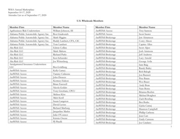
Using Emergency Lighting as Normal Lighting (ESRN & ESRB) button, controller, or re alarm panel Overriding a 0-10Vdc Dimmer (ESRN & ESRB) R Y Normal Power Feedback Status (Dry Contact Output) Normal / Emergency Lighting Wall Switch Automatic Transf er Switch Utility H ot Utility Neutral N