Transcription
www.cree.com/XlampCree XLamp CX Family LEDDesign GuideCopyright 2013-2015 Cree, Inc. All rights reserved. The information in this document is subject to change without notice. Cree , the Cree logoand XLamp are registered trademarks of Cree, Inc. UL is a registered trademark of UL LLC. All other trademarks, products, and company namesmentioned in this document are the property of their respective owners. This document is provided for informational purposes only and is not awarranty or a specification. For product specifications, please see the data sheets available at www.cree.com. For warranty information, please contactCree Sales at sales@cree.com.CLD-DG02 rev 3AProduct design GuideCree, Inc.4600 Silicon DriveDurham, NC 27703USA Tel: 1.919.313.5300i
CX Family Design GuideTable of ContentsIntroduction. . . . . . . . . 1CX Family LED How‑To.26About This Design Guide.1How To Select a Specific CX Family LED - the ProductThank You.1Characterization Tool.26CX Family Product Cautions.2How to Select a Driver.27Storage & Handling.2How to Assemble a CX Family LED into a LightingMechanical Design.3System.27Typical Assembly.3Safety & Compliance.29Connectors.3Summary.29Connector Resources.3Design Examples.30Mechanical Damage to Light Emitting Surface.6Decorative.30Preventing Damage to CX Family rmal Design.9Track Light.32Heat & Lifetime.9Heat & Light Output.10Ambient Temperature Measurement.10Thermocouple Attachment.11Luminaire Case Temperature Measurement.11Operating Limits.12Low Temperature Operation.12Heat Sink Flatness and Cleanliness.12Thermal Interface Materials.13Thermal Design Resources.19Electrical Considerations.19Multiple CX Family LEDs.19Electrical Overstress/Hot-Plugging.19Dielectric Voltage Withstand Testing.20Reverse Voltage.21Chemical Compatibility.21Chemical Resources.21Hermetically Sealing Luminaires.22Optical Considerations.22Optical Design.22CX Family Lens Material Considerations.23CX Family LEDs and Silicone.23CX Family Light Emitting Surface Comparison.24Optical Design Resources.24Copyright 2013-2015 Cree, Inc. All rights reserved. The information in this document is subject to change without notice. Cree , the Cree logo and XLamp are registeredtrademarks of Cree, Inc. UL is a registered trademark of UL LLC. All other trademarks, products, and company names mentioned in this document are the property of theirrespective owners. This document is provided for informational purposes only and is not a warranty or a specification. For product specifications, please see the data sheets availableat www.cree.com. For warranty information, please contact Cree Sales at sales@cree.com.ii
CX Family Design GuideIntroductionThis guide simplifies the CX family luminaire design effort by providing basic information on the requirements to use Cree XLamp CXfamily LEDs successfully in luminaire designs, with appropriate consideration for mechanical, electrical, thermal and optical design andchemical compatibility. In addition, the Cree Solution Provider (CSP) program assists lighting manufacturers in identifying componentsand materials that work with Cree LEDs.In this document, the term CX family LEDs refers to Cree’s ceramic substrate CXA and CXB LEDs, i.e., all the CXA and CXB LEDs exceptthe CXA2011.Cree’s CX family LEDs deliver high lumen output and efficacy in a family of single, easy‑to‑use components. CX family LEDs enablelighting manufacturers to quickly add LED products to their product portfolio. With Cree’s CX family LEDs, lighting manufacturers can haveperformance, reliability and ease-of-use in a single LED.This design guide explains how CX family LEDs and assemblies containing these LEDs should be handled during manufacturing. Pleaseread this entire document to understand how to properly design with and handle CX family LEDs.About This Design GuideThis design guide provides critical design guidelines, principles and best practices for successfully integrating the XLamp CX family LEDinto new and existing luminaire designs. For additional product information or samples, please contact your Cree sales representative. For technical information and support, please e-mail us at productsupport@cree.com.Consult the CX family soldering and handling document for additional information on the proper procedures to solder and handle CXfamily LEDs.Thank YouThank you for choosing to incorporate the XLamp CX family LED into your luminaire designs.If you need assistance, Cree Services will support you with thermal testing assistance for lifetime analysis, available from Cree’s Thermal,Electrical, Mechanical, Photometric and Optical tests (TEMPO) for LED luminaires.Copyright 2013-2015 Cree, Inc. All rights reserved. The information in this document is subject to change without notice. Cree , the Cree logo and XLamp are registeredtrademarks of Cree, Inc. UL is a registered trademark of UL LLC. All other trademarks, products, and company names mentioned in this document are the property of theirrespective owners. This document is provided for informational purposes only and is not a warranty or a specification. For product specifications, please see the data sheets availableat www.cree.com. For warranty information, please contact Cree Sales at sales@cree.com.1
CX Family Design GuideCX Family Product Cautions XLamp CX family LEDs must be electrically connected to an unenergized driver before applying power. “Hot plugging,” i.e., making aconnection from a CX family LED to an energized driver, may cause irreparable damage and will void the product warranty. All installations and applications of CX family LED-based luminaires are subject to the electrical, construction and building codesin effect in the final installation location. Installation by professionals having experience in the area of electrical lighting and formalinspection by the Authorities Having Jurisdiction (AHJ) is strongly recommended. Thermal characteristics of CX family LEDs are affected by the luminaire and by the conditions in which the luminaire is installed. Allfinal luminaire products should be evaluated in actual worst case installation conditions. Thermal limits of the CX family LED mustbe maintained for warranty consideration.CX family LED surfaces may be hot during operation. Take care during handling to avoid burns.Do not look directly at an energized CX family LED without proper eye safety precautions or diffusive shielding.Failure to follow the design guidelines in this document may void the product warranty and may present a hazard to property or personnel.Storage & HandlingStore XLamp CX family LEDs in their original packaging to minimize potential for unintended contact and contamination.CX family LEDs must be handled with proper electrostatic discharge (ESD) handling protocols. Remove CX family LEDs from their packageat an ESD‑safe workstation and use appropriate handling protocols and precautions when handling and soldering connections to the CXfamily LED. Handle CX family LEDs in a clean environment, i.e., free from particulates, oil residues, etc. Do not touch the light‑emitting surface (LES) of a CX family LED with tools or fingers. The LES is the part of the LED from which lightis emitted. In the pictures on the cover page of this guide, the yellow or orange circle on each CX family LED is the LES. Do not allow foreign material to touch the LES of a CX family LED. Do not assemble CX family LED‑based luminaires in an environment in which foreign material can come in contact with the LED. Material should be cleaned from a CX family LED by gently blowing the material off the LED with clean dry air (CDA) or by wiping theLED with a lint‑free swab dipped in isopropyl alcohol (IPA).Copyright 2013-2015 Cree, Inc. All rights reserved. The information in this document is subject to change without notice. Cree , the Cree logo and XLamp are registeredtrademarks of Cree, Inc. UL is a registered trademark of UL LLC. All other trademarks, products, and company names mentioned in this document are the property of theirrespective owners. This document is provided for informational purposes only and is not a warranty or a specification. For product specifications, please see the data sheets availableat www.cree.com. For warranty information, please contact Cree Sales at sales@cree.com.2
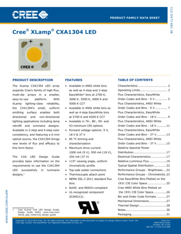
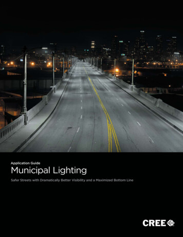
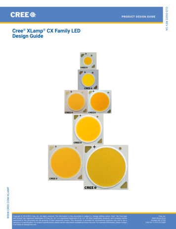
CX Family Design GuideMechanical DesignTypical AssemblyCX family LEDs are generally attached directly to a heat sink and discrete wires are used to deliver power to the LED, as illustrated inFigure 1. A thermal interface material (TIM) must be applied between the CX family LED and the heat sink to properly maintain thermalperformance.Without the use of a connector to attach a CX family LED to a heat sink, apply thermal adhesive or thermal tape between the CX familyLED and the heat sink.With a connector, apply thermal adhesive, thermal tape, a thermal pad, thermal grease, gel, gap filler or heat spreader between the CXfamily LED and the heat sink.Screw WireConnector- WireCXA- WireTIMHeat sinkFigure 1: CX family LED connected to heat sink, left: without a connector, right: with a connectorConnectorsThe use of a connector to attach a CX family LED to a heat sink simplifies the mechanical fastening of the CX family LED to the heat sinkand can help with aligning a secondary optic with the LES. The use of a connector can also ensure proper clamping force is applied to theCX family LED, minimizing the potential for damage. Additionally, because a connector covers the LED’s electrical connections, use of aconnector simplifies the safety and regulatory certification process.Connector ResourcesTable 1 contains model numbers and characteristics for connectors available from Interconnect Solution Providers that participate in theCSP program. Each supplier name and model number is a link to additional information on the connector. These suppliers can provideassistance with connectors and connector information.Copyright 2013-2015 Cree, Inc. All rights reserved. The information in this document is subject to change without notice. Cree , the Cree logo and XLamp are registeredtrademarks of Cree, Inc. UL is a registered trademark of UL LLC. All other trademarks, products, and company names mentioned in this document are the property of theirrespective owners. This document is provided for informational purposes only and is not a warranty or a specification. For product specifications, please see the data sheets availableat www.cree.com. For warranty information, please contact Cree Sales at sales@cree.com.3
CX Family Design GuideTable 1: CX family connector model numbersCX Family LED/CharacteristicSupplier Model 50.5050-2234CCXA35XXCXB35XXKang RongMolexSMKTE 857-250-2303CRScrew sizeM3#4, #5, M3M2.5, M3M2.5, M3M3No. 4 or M3x6-mm(minimum)Maximum torque for screw(Nm)0.50.3-0.50.50.4-0.80.3 10%0.28-0.45Reflectivity97%Zhaga Book 3 compliantYesNoNoNo96%YesNoCree recommends following the connector manufacturer’s recommendations for both the amount of torque to apply to the connector andthe TIM thickness.Table 2 shows some of the optics available for CX family LED connectors. For more optics solutions, see Table 8.Table 2: CX family LED connectors and opticsCX FamilyLEDCXA13XXCXB13XXConnector VendorConnectorPart NumberBJB47.319.6120.50Ideal50-2000CROptic Part NumberCarcloGaggioneKhatodLEDiLIdeal LEDiLAdaptor10755.0010754.00Kang RongMolexSMKCXA15XXCXB15XXTE 01CR10755.0010754.00MirellaKang RongMolex180560-0001SMKTE Connectivity2-2154857-3Copyright 2013-2015 Cree, Inc. All rights reserved. The information in this document is subject to change without notice. Cree , the Cree logo and XLamp are registeredtrademarks of Cree, Inc. UL is a registered trademark of UL LLC. All other trademarks, products, and company names mentioned in this document are the property of theirrespective owners. This document is provided for informational purposes only and is not a warranty or a specification. For product specifications, please see the data sheets availableat www.cree.com. For warranty information, please contact Cree Sales at sales@cree.com.4
CX Family Design GuideCX FamilyLEDCXA18XXCXB18XXConnector VendorConnectorPart NumberBJB47.319.2130.50Ideal50-2101CROptic Part NumberCarcloGaggioneLLC56NLLR05NKhatodLEDiLIdeal LEDiLAdaptorF13659 ANGELINA-S-BF13660 ANGELINA-M-BF13661 ANGELINA-W-BF13839 ANGELINA-XW-BF13662 ANGELA-S-BF13663 ANGELA-M-BF13664 ANGELA-W-BF13841 0-2100ANKang RongMolexSMKTE 01CRKang RongMolexSMKTE 0.50Ideal50-2102CRLLC56NLLR05NF13659 ANGELINA-S-BF13660 ANGELINA-M-BF13661 ANGELINA-W-BF13839 ANGELINA-XW-BF13662 ANGELA-S-BF13663 ANGELA-M-BF13664 ANGELA-W-BF13841 ANGELA-XW-BLenaAngelina50-2100LN50-2100ANKang TE 34CLLC56NLLR05NF13659 ANGELINA-S-BF13660 ANGELINA-M-BF13661 ANGELINA-W-BF13839 ANGELINA-XW-BF13662 ANGELA-S-BF13663 ANGELA-M-BF13664 ANGELA-W-BF13841 ANGELA-XW-BLenaAngelina50-2100LN50-2100ANKang RongMolexSMKCLE9902-1391FTE Connectivity2-2154857-2Copyright 2013-2015 Cree, Inc. All rights reserved. The information in this document is subject to change without notice. Cree , the Cree logo and XLamp are registeredtrademarks of Cree, Inc. UL is a registered trademark of UL LLC. All other trademarks, products, and company names mentioned in this document are the property of theirrespective owners. This document is provided for informational purposes only and is not a warranty or a specification. For product specifications, please see the data sheets availableat www.cree.com. For warranty information, please contact Cree Sales at sales@cree.com.5
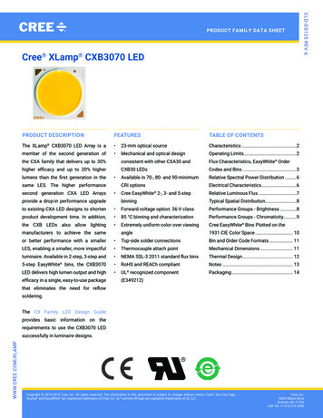
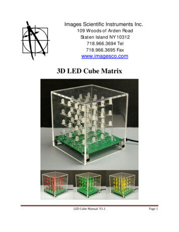
CX Family Design GuideCX FamilyLEDConnector VendorConnectorPart NumberOptic Part NumberCarcloGaggioneKhatodLEDiLIdeal X50-2303CRKang RongMolexSMKTE ConnectivityMechanical Damage to Light Emitting SurfaceAt no time should anything (tools, optics, hands) come in contact with the LES of a CX family LED. Such contact will damage the LED.Cree performed tests to replicate handling that can damage the CX family LED LES. Figure 2 shows downward force being applied to a CXfamily LED LES. Figure 3 shows bent (blue arrows) and broken (red arrows) bond wires in a CX family LED due to force applied to the LES.Figure 4 shows a CX family LED that is only partially illuminated due to handling that damaged bond wires in the LED.Figure 2: Force applied to CX family LEDFigure 3: Damaged bond wires due to improperhandling of CX family LEDFigure 4: Partially illuminated CX family LED dueto damaged bond wiresPreventing Damage to CX Family LEDsThe force needed to fracture a CX family LED depends on many factors including the flatness of the material onto which the LED ispressed, the hardness and thickness of the material, how the CX family is stressed and where on the LED the stress is applied.Cree recommends a maximum force of no more than 75 foot‑pounds (101.7 Newton‑meters) be applied to a CX family LED on a flatsurface.It takes less force to damage a CX family LED on a non-flat surface. The amount of force depends on the geometry of the non‑flat surface,how the force is applied and where on the LED the force is applied. As recommended in the Heat Sink Flatness and Cleanliness section onpage 12, attaching a CX family LED to a flat heat sink surface is advised. This not only enables good thermal contact, but also supportsthe CX family LED uniformly so the ceramic will not break under normal force conditions. Using a thick, soft TIM or a non-flat surfacereduces the allowable force on a CX family LED and application‑specific testing is strongly advised in such a situation.Handling/AssemblyDo not attach screws directly to a CX family LED, not even with the use of plastic washers. Doing so will damage the LED. Figure 5 is anexample of improperly attaching a CX family LED to a heat sink.Copyright 2013-2015 Cree, Inc. All rights reserved. The information in this document is subject to change without notice. Cree , the Cree logo and XLamp are registeredtrademarks of Cree, Inc. UL is a registered trademark of UL LLC. All other trademarks, products, and company names mentioned in this document are the property of theirrespective owners. This document is provided for informational purposes only and is not a warranty or a specification. For product specifications, please see the data sheets availableat www.cree.com. For warranty information, please contact Cree Sales at sales@cree.com.6
CX Family Design GuideFigure 5: Do not attach CX family LED with screwsFigure 6 shows proper and improper handling of CX family LEDs with fingers and tweezers. Wear clean, lint‑free gloves when handling CXfamily LEDs. Doing so helps to keep the LES clean. Do not touch the LES with fingers, gloved fingers or tools.Proper HandlingImproper HandlingFigure 6: Correct and incorrect handling of CX family LED with fingers and tweezersIf wires are to be manually soldered to a CX family LED, Cree recommends using wire of the gauge shown in Table 3. These gauges applywhen operating the CX family LED at its maximum current. If a lower current is used, a smaller gauge wire can be used. The wire striplength depends on the size of the CX family LED and should be no longer than the length of the solder pad, as shown in Table 3.Copyright 2013-2015 Cree, Inc. All rights reserved. The information in this document is subject to change without notice. Cree , the Cree logo and XLamp are registeredtrademarks of Cree, Inc. UL is a registered trademark of UL LLC. All other trademarks, products, and company names mentioned in this document are the property of theirrespective owners. This document is provided for informational purposes only and is not a warranty or a specification. For product specifications, please see the data sheets availableat www.cree.com. For warranty information, please contact Cree Sales at sales@cree.com.7
CX Family Design GuideTable 3: CX family manual soldering wire gauge and wire strip lengthWire GaugeLEDWire Strip LengthAWGmminmm9V210.410.0751.918 V240.2050.0751.936 V270.1020.0751.918 V210.410.0751.936 V240.2050.0751.918 V220.3260.0751.936 V250.1620.0751.918 V210.410.0751.936 V230.2580.0751.9CXA1512CXB151218 V210.410.0751.936 V230.2580.0751.9CXA152036 V220.3260.0751.9CXA1816CXB181636 V220.3260.0751.9CXA1820CXB182036 V210.410.0751.9CXA1830CXB183036 V200.5180.0751.9CXA185036 V180.8230.0751.9CXA252036 V200.5180.1062.7CXA2530CXB253036 V190.6530.1062.7CXA2540CXB254036 V180.8230.1062.7CXA259072 V190.6530.1062.7CXA3050CXB305036 V171.040.1062.7CXA3070CXB307036 V171.040.1062.736 V171.040.1263.272 7CXA1510CXA3590CXB35902As illustrated in Figure 7, wire should not protrude outside the contact pad to minimize the potential to damage the LES or short aroundthe ceramic dielectric. Any residual flux should be cleaned with IPA to minimize the potential for contamination or degradation of thesilicone.Copyright 2013-2015 Cree, Inc. All rights reserved. The information in this document is subject to change without notice. Cree , the Cree logo and XLamp are registeredtrademarks of Cree, Inc. UL is a registered trademark of UL LLC. All other trademarks, products, and company names mentioned in this document are the property of theirrespective owners. This document is provided for informational purposes only and is not a warranty or a specification. For product specifications, please see the data sheets availableat www.cree.com. For warranty information, please contact Cree Sales at sales@cree.com.8
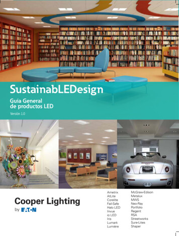
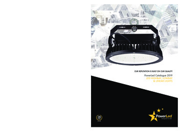
CX Family Design GuideFigure 7: Left: Wires improperly attached to CX family LED, center: wires should not protrude beyond solder pads,right: excessive solder flux should be cleanedThermal DesignHeat & LifetimeXLamp CX family LEDs are designed to perform over a range of operating temperatures. As with all LEDs, their expected lifetimes dependon their operating temperature. When designing a luminaire that incorporates CX family LEDs, careful consideration must be taken toensure a sufficient thermal path to ambient is provided. Verification of a proper thermal path is done on the finished luminaire in theintended application by attaching a thermocouple at the Tc measurement point indicated in Figure 8 for each CX family LED.Copyright 2013-2015 Cree, Inc. All rights reserved. The information in this document is subject to change without notice. Cree , the Cree logo and XLamp are registeredtrademarks of Cree, Inc. UL is a registered trademark of UL LLC. All other trademarks, products, and company names mentioned in this document are the property of theirrespective owners. This document is provided for informational purposes only and is not a warranty or a specification. For product specifications, please see the data sheets availableat www.cree.com. For warranty information, please contact Cree Sales at sales@cree.com.9
CX Family Design 25XXCXB25XXCXA30XXCXB30XXCXA35XXCXB35XXFigure 8: Tc measurement point for CX family LEDsA summary of the LM-80 test results with reported TM-21 lifetimes is available on the Cree website. Contact your Cree sales representativeto request an LM-80 report for a CX family LED. Contact your Cree Field Applications Engineer (FAE) to request TM-21 projections.Heat & Light OutputAll CX family LEDs are rated for their nominal lumen output at a Tc of 85 C. Temperature change from this point inversely affects thelumen output of the CX family LED.The Operating Limits section of each CX family LED’s data sheet gives the maximum current and Tc conditions under which the LEDoperates successfully. At operating temperatures above a certain point, different for different LEDs, the current level must be de ‑rated, i.e.,lowered, to allow the LED to operate at peak effectiveness. See the Operating Limits section on page 12 for more information.Ambient Temperature MeasurementThe ambient temperature of the test environment must be monitored and recorded with the required data during a temperature test. Thepreferred ambient temperature measurement apparatus is described in UL1598-2008 Rev January 11, 2010, Section 19.5. The intent ofthis requirement is to ensure that the temperature monitored does not fluctuate. Note that bare thermocouple wires in open air is not anacceptable method of recording the ambient temperature.Copyright 2013-2015 Cree, Inc. All rights reserved. The information in this document is subject to change without notice. Cree , the Cree logo and XLamp are registeredtrademarks of Cree, Inc. UL is a registered trademark of UL LLC. All other trademarks, products, and company names mentioned in this document are the property of theirrespective owners. This document is provided for informational purposes only and is not a warranty or a specification. For product specifications, please see the data sheets availableat www.cree.com. For warranty information, please contact Cree Sales at sales@cree.com.10
CX Family Design GuideThermocouple AttachmentAttach a thermocouple to the Tc point indicated in Figure 8. The attachment method described in UL1598-2008 Rev January 11, 2010,Section 19.7.4 is preferred; using silver-filled thermal epoxy is an acceptable alternative. Ensuring that the tip of the thermocouple properlycontacts the LED at the Tc location and that the attachment method does not add thermal resistance to the test is critical to correct andacceptable testing. A thin ( 30 AWG, 0.05 mm2) Type T thermocouple can be easily and quickly soldered directly to the Tc point. Type Jand K thermocouples are also very popular, however, they cannot be soldered and must be attached with an adhesive.Do not place the thermocouple tip directly on the LES. A temperature measured at the LES will be inaccurate and taking a measurementthis way can damage the LED. Figure 9 shows a thermocouple properly attached to a CX family LED.Figure 9: Thermocouple properly attached to CX family LED,left: thermocouple wire does not cross the LES, right: thermocouple attachment in close‑upNote - Quick-drying adhesives and other cyanoacrylate-based products are known to be destructive, over time, to thecomponents and adhesives used in solid‑state lighting products. The use of cyanoacrylate‑based products is at thediscretion of the testing organization. Cyanoacrylate adhesives should not be used in any luminaire design or for anylong‑term testing.Luminaire Case Temperature MeasurementOnce the thermocouple is properly attached at the Tc location, assemble the CX family LED into the luminaire. The luminaire must then betested in its intended environment or that environment which will result in the highest recorded temperature. Take care during assemblyto ensure that the thermocouple remains properly attached and that the thermocouple wire is not in the light emission path from the LED.One precaution to ensure the thermocouple remains attached to the LEDis to use tape to provide strain relief. Energize the luminaire andallow the assembly to reach thermal equilibrium. Thermal stabilization may require several hours, depending on the mechanical design.Once thermal equilibrium is achieved, record the room ambient and case temperatures. Measure the CX family LED case temperature atthe designated case temperature measurement point, adjacent to the anode or plus ( ) solder pad. This measurement point is shown inFigure 8.There is no need to calculate for TJ inside the package, as the thermal management design process, specifically from TSP to ambient (Ta),remains identical to any other LED component. For additional information on Tc measurement, refer to the Solder‑Point TemperatureMeasurement application note.Copyright 2013-2015 Cree, Inc. All rights reserved. The information in this document is subject to change without notice. Cree , the Cree logo and XLamp are registeredtrademarks of Cree, Inc. UL is a registered trademark of UL LLC. All other trademarks, products, and company names mentioned in this document are the property of theirrespective owners. This document is provided for informational purposes only and is not a warranty or a specification. For product specifications, please see the data sheets availableat www.cree.com. For warranty information, please contact Cree Sales
lighting manufacturers to quickly add LED products to their product portfolio. With Cree’s CX family LEDs, lighting manufacturers can have performance, reliability and ease-of-use in a single LED. This design guide explains how CX family LEDs and assemblies containing